SlideShare une entreprise Scribd logo
1  sur  7
Télécharger pour lire hors ligne
IOSR Journal of Electrical and Electronics Engineering (IOSR-JEEE)
e-ISSN: 2278-1676,p-ISSN: 2320-3331, Volume 11, Issue 1 Ver. III (Jan. – Feb. 2016), PP 29-35
www.iosrjournals.org
DOI: 10.9790/1676-11132935 www.iosrjournals.org 29 | Page
Design and Modeling of LSRM Driven Infusion Pump
Praveen Kumar C 1
, Vishnu R Nedungadi2
, Dr K Geetha3
1
Assistant Professor, EEE Department, NSS College of Engineering, Palakkad
2
PG Scholar, EEE Department NSS College of Engineering, Palakkad
3
Principal, NSS College of Engineering, Palakkad
Abstract: Infusion Pump is a precision electromechanical device used to administer a required amount of
highly potent medicines to the patient over a period of time. The Linear Switched Reluctance Motor based
design of this pump improves the resolution and the power utilization of the motor without increasing the cost or
compromising any other aspect of the device.
I. Introduction
The Linear Switched Reluctance Motor is widely used in many industries nowadays. This is due to the
advancements made in the power semiconductor devices and associated technology. These motors have a robust
build and the added advantage of lack of transmission systems in the form of belts and gears for the attainment of
linear movement. The objective of this paper is to model the Linear Switched Reluctance Motor for the specific
application and also to control the actuator movement for the motorization of the syringe pump. A control
algorithm optimized for closed-loop control of the motor is obtained with a PI Controller and Hysteresis Current
Controller is used to obtain proper functioning of the device. The present day biomedical engineers employ
stepper motors for this purpose. Theses stepper motors in conjunction with some transmission systems to obtain
the linear movement is used for this purpose. The motorization of these biomedical systems is generally provided
by a rotating stepping motor associated to a gear unit. The shaft of the stepper motor connects the syringe, is
bulky, expensive and requires frequent maintenance. The reliability is considerably more compared to the
previous models of infusion pumps. The basic architecture of the proposed system is shown in figure 1.Here the
LSRM is used to push the syringe piston to administer the medicine to the patient. The movement of the LSRM
is controlled to deliver the right amount of dosage over the required amount of time. In effect, we are controlling
the speed of the LSRM in order to regulate the amount of medicine administered to the patient. A better force
profile, improved performance characteristics and a robust build of the linear switched reluctance motor makes it
a perfect candidate to replace the stepper motors in the infusion pumps.
Figure 1: Basic architectureof LSRM driven Infusion Pump.
II. Design Of LSRM
The actuator proposed is a linear switched reluctance motor composed by a toothed sliding part on
rail.The stator modules are regularly distributed. The stator windings are laminated copper and concentrated
around the cylinder heads of the stator.These coils are excited by DC currents. The non-magnetic separations
between the different modules impose a regular shift. If teeth of an active module are aligned with teeth of the
translator or the moving part of the LSRM,, the other stator modules must be unaligned in order to create a
translation force.We can move from a step command to another only when the actuator responded satisfactorily
to the previous command and so there is no possibility of losing synchronism. The position sensor thus has to
perform two functions
-Detect the equilibrium positions to generate the next step command to follow the excitation sequence without
missing excited phases.
Design And Modeling Of Lsrm Driven Infusion Pump
DOI: 10.9790/1676-11132935 www.iosrjournals.org 30 | Page
-Continuous detection of the position of the translator to implement closed loop control. This will enable the
correction of the position using controllers solves the problems of overshoot and oscillations.
A standard design procedure for a linear switched reluctance machine (LSRM) is discussed next. The
proposed design procedure utilizes the rotating switched reluctance machine (RSRM) design by converting the
specifications of the linear machine into an equivalent rotating machine. The machine design is carried out in the
rotary domain, which then is transformed back in to the linear domain. Such a procedure brings to bear the
knowledge base and familiarity of the rotary machine designers to design a linear machine effectively. The
design of LSRM is achieved by first translating its specifications into equivalent rotary SRM specifications. Then
the rotary SRM is designed from which the LSRM dimensions and design variables are recovered by inverse
translation.
Design Procedure
The LSRM is to be designed for a machine stator lengthLt, with a maximum linear velocity of vm and
an acceleration time ta required to reach the maximum velocity. The maximum mass of translator is restricted to
Mt. Figure 2 shows the required velocity profile of the LSRM. If the deceleration time td = ta, the maximum
acceleration is given by,
𝑎 𝑎 =
𝑉 𝑚
𝑡 𝑎
(1)
and the maximum deceleration 𝑎 𝑑 = −𝑎 𝑎. The instantaneous acceleration force 𝐹𝑎 is given by,
𝐹𝑎 = 𝑀𝑡 𝑎 𝑎 (2)
and the instantaneous deceleration force
𝐹𝑑 = −𝐹𝑎. (3)
Assuming a zero instantaneous friction force, 𝐹𝑓 = 0, the maximum power capacity of LSRM is given by,
𝑃 = 𝐹𝑎 × 𝑣 𝑚 (4)
Figure 2 Velocity and Required Force Profiles of LSRM
Design of Rotary SRM
An LSRM prototype is designed for a length of 30cm, with a maximum linear velocity of 30cm/hr and
acceleration time of 1 second. The maximum mass of translator assembly is restricted to 10 kg.
Acceleration is given by,
𝑎 𝑎 =
𝑉𝑚
𝑡 𝑎
= 8.33 × 10 𝑚/𝑠2
Force for initial acceleration is set as
𝐹𝑎 = 100 𝑁
The deceleration, ad= -8.33m/s2
and deceleration force Fd= –100 N
Power capacity of LSRM is
𝑃 = 𝐹𝑎 × 𝑉𝑚 = 9𝑊
The RSRM is assumed to have a stator pole angle, βs= 30° = 0.524 rads and rotor pole angle of βr= 36°= 0.628
rads.
The power output equation of an RSRM in terms of key physical variables, is described by
𝑃 = 𝑘 𝑒 𝑘 𝑑 𝑘1 𝑘2 𝐵𝑔 𝐴 𝑠𝑝 𝐷2
𝐿𝑁𝑟 (5)
where P is the power output, ke is the efficiency, k is the duty cycle determined by the current conduction angle
for each rising inductance profile, k1= 1/4, k is a variable dependent on the operating point and is determined by
using aligned saturated inductance and unaligned inductance, Bg is the flux density in the air gap at the aligned
Design And Modeling Of Lsrm Driven Infusion Pump
DOI: 10.9790/1676-11132935 www.iosrjournals.org 31 | Page
position, Asp is the specific electric loading which is defined as ampere conductor per meter of stator inner
periphery, L is the stack length of the magnetic core, and Nr is the speed.
After fine tuning the parameters using Finite Element analysis, the constants are set as follows:
ke= 0.4, kd= 1, k2= 0.7, Bg=1215mWb, Asp= 0.23886 and k= 0.655
Converting the rotational angular velocity to linear velocity,
𝑃 = 𝑘 𝑒 𝑘 𝑑 𝑘1 𝑘2 𝐵𝑔 𝐴 𝑠𝑝 𝐷2
𝑘𝐷
𝑣 𝑚
𝐷
2
60
2𝜋
(6)𝑃 = 𝑘 𝑒 𝑘 𝑑 𝑘1 𝑘2 𝐵𝑔 𝐴 𝑠𝑝 𝐷2
𝑣 𝑚
60
2𝜋
(7)
Bore diameter,
𝐷 =
𝑃𝜋
60 𝑘 𝑒 𝑘 𝑑 𝑘1 𝑘2 𝐵 𝑔 𝐴 𝑠𝑝 𝑣 𝑚
= 97.72 mm (8)
Setting the stack length of RSRM as a multiple or submultiple of the bore diameter,
L= kD = 64.06 mm (9)
The air gap of the LSRM is usually much larger than that of the RSRM. In the aligned portion, the B-H
characteristic of the magnetic material is fairly linear and the reluctance of the steel core is very small when
compared to the reluctance of the air gap in the aligned position. The machine flux linkage can be calculated as
∅ = 𝐵𝑔 𝐴 𝑔 (10)
where𝐴 𝑔 is the area of cross section of the air gap and during alignment is approximately
𝐴 𝑔 =
𝐷
2
− 𝑔
𝛽 𝑟+ 𝛽 𝑠
2
𝐿(11)
where g is the length of the air gap. Magnetic field intensity in the air gap is calculated as,
𝐻𝑔 =
𝐵 𝑔
𝜇0
= 892461.3
𝐴
𝑚
(12)
Assuming the existence of a large air gap, the ampere-turns required to produce the air gap magnetic field
intensity is given by,
𝑇𝑝𝑕 𝐼𝑝 = 𝐻𝑔2𝑔(13)
whereTph is the number of winding turns per phase and Ip is the peak phase winding current. Assuming a peak
phase winding current Ip= 0.5 A, allowable in the machine, the number of turns per phase of the RSRM can be
calculated as,
𝑇𝑝𝑕 =
𝐻𝑔2𝑔
𝐼𝑝
= 210 𝑡𝑢𝑟𝑛𝑠/𝑝𝑕𝑎𝑠𝑒
If J is the maximum allowable current density in the winding and m is the number of phases, the cross-section
area of a conductor is calculated as,
𝑎 𝑐 =
𝐼 𝑝
𝐽 𝑚
(14)
For a maximum current density of
J = 6A/mm2
, 𝑎 𝑐 = 0.818 𝑚𝑚2
.
Neglecting the leakage of flux linkages, the area of the stator pole, the flux density in the stator pole, the area of
the stator yoke, and the height of the stator pole can be calculated, respectively, as,
𝐴 𝑠 =
𝐷𝐿𝛽 𝑠
2
(15)
𝐵𝑠 =
∅
𝐴 𝑠
(16)
𝐴 𝑦 = 𝐶𝑠𝑦 𝐿 =
𝐴 𝑠 𝐵 𝑠
𝐵 𝑦
(17)
𝑕 𝑠 =
𝐷0
2
−
𝐷
2
− 𝐶𝑠𝑦 (18)
Stator yoke thickness, Csy is given by
Csy =
D βs
2
= 25.60mm (19)
Assuming D0= 190 mm height of stator pole, 𝑕 𝑠 = 27.815 mm.
where𝐶𝑠𝑦 is the thickness of the yoke and D0 is the outer diameter of the stator lamination. The rotor pole area is
given by,
𝐴 𝑟 =
𝐷
2
− 𝑔 𝐿𝛽𝑟 (20)
If the rotor yoke has a radius equal to the width of the rotor pole, the rotor yoke width and the height of the rotor
pole are sequentially calculated as,
Cry =
D
2
βr
= 30.68 mm (21)
hr =
D
2
− g − Cry =20.45 0mm (22)
This completes the analytical relationships required for the RSRM design.
Design And Modeling Of Lsrm Driven Infusion Pump
DOI: 10.9790/1676-11132935 www.iosrjournals.org 32 | Page
Conversion from RSRM Dimensions to LSRM Dimensions:
The bore circumference of the RSRM forms the length of one sector of the LSRM. The total number of
sectors of the LSRM is given by,
𝑁𝑠𝑐 =
𝐿 𝑡
𝜋𝐷
= 22 (23)
For the number of poles 𝑁𝑠 in the stator of the RSRM, the number of stator poles is obtained by,
𝑛 = 𝑁𝑠 𝑁𝑠𝑐 = 132(24)
Width of stator pole and width of stator slot are given by,
𝑊𝑠𝑝 =
𝐷𝛽 𝑠
2
= 30.68 𝑚𝑚 (25)
𝑊𝑠𝑠 =
𝜋𝐷−6𝑊𝑠𝑝
6
= 20.49 𝑚𝑚(26)
Translator pole width and translator slot width are,
𝑊𝑡𝑝 = Cry = 30.68 mm(27)
𝑊𝑡𝑠 =
𝜋𝐷−4𝑊𝑡𝑝
4
= 46.07 𝑚𝑚 (28)
Total length of the translator is given by,
𝐿𝑡𝑟 = 6𝑊𝑡𝑃 + 5𝑊𝑡𝑠 = 414.43 𝑚𝑚(29)
The core stack width of the LSRM is obtained from stator stack length of RSRM as,
𝐿 𝑤 = 𝐿 = 𝐾𝐷 = 64.06 𝑚𝑚 (30)
Diameter of the conductor is given by,
𝑑 𝑐 =
4𝑎 𝑐
𝜋
= 1.02 𝑚𝑚 (31)
Assuming width of wedges, w= 3 and packing factor, ff= 0.8, number of vertical layers of winding and number
of horizontal layers of winding are obtained as,
𝑁𝑣 = 𝑓𝑓
𝑕 𝑠−𝑤
𝑑 𝑐
= 20 (32)
𝑁𝑕 =
𝑇 𝑝 𝑕
2 𝑁 𝑣
= 7 (33)
Stator winding area is given by,
2 𝑎 𝑐 𝑁 𝑣 𝑁 𝑕
𝑓 𝑓
= 286.3 𝑚𝑚2
(34)
Fill factor is calculated as,
𝑓𝑓 =
𝑠𝑡𝑎𝑡𝑜𝑟𝑤𝑖𝑛𝑑𝑖𝑛𝑔𝑎𝑟𝑒𝑎
𝑠𝑡𝑎𝑡𝑜𝑟𝑠𝑙𝑜𝑡𝑤𝑖𝑛𝑑𝑜𝑤𝑎𝑟𝑒𝑎
= 0.499 (35)
III. Proposed System Simulation In SRM Model
The simulation model for the Linear Switched Reluctance Motor based infusion pump is as shown below.
The simulation is carried out in the Switched Reluctance Motor Model available in the MATLAB/SIMULINK. A
Linear Switched Reluctance Motor is basically a Switched Reluctance motor cut radially and spread out on a
surface. The working of the two variations of the reluctance motor is exactly the same. Hence we use the SRM
Model which is available in the MATLAB to obtain the simulation for the LSRM model.
Figure3. Closed loop control of LSRM
The position controller block is as shown in fig.4.12. The angular velocity is converted into radians using
an integrator. The modulus operator output is taken to the relational operator. The modulus operator output value
will always be less than 90 degrees. The firing is required between 40-75 degrees for the optimum operation of the
motor. The speed controller block is as shown in fig.4. The output of the two blocks is taken to a multiplexer. The
output of the multiplexer will serve as the current reference. The current output from the previous instant and the
Design And Modeling Of Lsrm Driven Infusion Pump
DOI: 10.9790/1676-11132935 www.iosrjournals.org 33 | Page
current reference is used to get the error in current value. This is given to the hysteresis controller. The output of
whose is used to generate the PWM signals required for the switching operation.
Figure.4: Speed controller block
The converter is provided for each phase. Two switches and two freewheeling diodes are provided in each
phase. Each of the two switches in a phase operates simultaneously. After their de-energizing the energy in the
winding of the phase is expended through the freewheeling diodes. This block is shown in figure 7 and the
consequent energizing for the corresponding windings is shown in figure6
Figure.5: Position sensor block
Figure.6: Converter topology for A Phase
Figure.7: SRM with Converter
The MATLAB Simulation output is as shown in figure.8
Design And Modeling Of Lsrm Driven Infusion Pump
DOI: 10.9790/1676-11132935 www.iosrjournals.org 34 | Page
Figure. 8 Simulation Result
IV. Conclusion
In this proposed system, an Infusion Pump using a Linear Switched Reluctance Motor is implemented.
The use of the switched reluctance motor eliminated the presence of the additional frictional encountered while
using a stepper motor. This is done by removing the need for a transmission system to obtain the linear movement.
The occurrence of oscillations in the movement of the Linear Switched Reluctance Motor is also greatly reduced
by ensuring a smooth and continuous motion of the translator of the motion.
Authors Profile
Mr.Praveen Kumar .C is workingpresently as Assistant Professor in the Electrical and
Electronics Engineering Dept. of NSS College of Engineering Palakkad. His research
areas include Plasma Physics, Electric Propulsion, Mechatronics, BiomedicalDevices
and Electromagnetism.
Vishnu R Nedungadi is a PG Scholar currently doing his M.Tech in Power Electronics
at N.S.S College of Engineering, Palakkad. His areas of interest include Power
Electronics, Power Systems and Control Systems.
DrKGeetha is working presently as Principal, NSS College of Engineering Palakkad. She obtained her
doctoral degree in Power Electronics. Her research areas include Power Electronics and Electrical
Drives.
References
[1] R Krishnan, Switched Reluctance Motor Drives: Modeling, Simulation, Analysis, Design, and Applications, 1st ed. Boca Raton,
FL: CRC, 2001.
[2] Byeong-Seok, Han-Kyung Bae, Praveen Vijayraghavan, and R. Krishnan, “Design of a linear switched reluctance machine”, IEEE
Transactions on Industrial Applications, Vol. 33, No. 3, November/December 2000, pp.1571-1580.
[3] Bae, Han-Kyung, Byeong-Seok Lee, Praveen Vijayraghavan, and R. Krishnan, “Linear switched reluctance motor: converter and
control”, in Conf. Rec. of the 1999 IEEE IAS Ann. Mtg., Oct. 1999, Phoenix, AZ, pp. 547–554.
[4] GeBaoming, Aníbal T. de Almeida, and Fernando J. T. E. Ferreira, “Design of Transverse Flux Linear Switched Reluctance
Motor”, IEEE Transactions on Magnetics, Vol. 45, No. 1, Jan 2009, pp.113-119.
[5] B. S. Lee, “Linear switched reluctance machine drives with electromagnetic levitation and guidance systems.” Ph.D. thesis, The
Bradley Department of Electrical and Computer Engineering, Virginia Tech., Blacksburg, VA, November 2000.
[6] Seok-Myeong Jang, Ji-Hoon Park, Dae-Joon You, Han-Wook Cho, Ho-Kyung Sung “Design of High Speed Linear Switched
Reluctance Motor”, Proceeding of International Conference on Electrical Machines and Systems 2007, Oct. 8~11, Seoul, Korea, pp.
1368-1671.
[7] N. S. Lobo, Hong Sun Lim, R Krishnan, “Comparison of Linear Switched Reluctance Machines for Vertical Propulsion
Application: Analysis, Design, and Experimental Correlation”, IEEE Transactions on Industrial Applications, Vol. 44, No. 4,
July/August 2008, pp. 1134- 1142.
Design And Modeling Of Lsrm Driven Infusion Pump
DOI: 10.9790/1676-11132935 www.iosrjournals.org 35 | Page
[8] MahirDursun, FatmagilKoc, “Linear switched reluctance motor control with PIC18F452 microcontroller”, Turkish Journal of
Electrical Engineering & Computer Sciences, Vol.21, pp.1107-1119.
[9] Antonio Eduardo Victoria, Maria, Carlos Manuel Pereira, “Design and Evaluation of Linear Switched Reluctance Actuator For
Positioning Tasks”, Turkish Journal of Electrical Engineering & Computer Sciences, Vol.18, No.6, 2010.
[10] Zhen Gang Sun, Nobert C Chung, Shi Wei Zhao, and Wai- Chen Gan, “Magnetic Analysis of Switched Reluctance Actuators in
Levitated Linear Transporters”, IEEE Transactions on Vehicular Technology, Vol.59, No.9, Nov.2010, pp.4280- 4288.
[11] Shi Wei Zhao, Norbert C. Cheung, Wai-ChuenGan, and Zhen Gang Sun, “A Novel Flux
Linkage Measurement Method forLinear Switched Reluctance Motors”, IEEE Transactions on Instrumentation and Measurement”,
Vol.58, No.10, October 2009, pp.3569-3575.
[12] J. F. Pan, Yu Zou, and Guangzhong Cao, “An Asymmetric Linear Switched Reluctance Motor”, IEEE Transactions on Energy
Conversion, Vol.28, No.2, June 2013, pp.444-451.
[13] Shi Wei Zhao, Norbert C. Cheung, Wai-ChuenGan, and Jin Ming Yang, “High-Precision Position Control of a Linear-
SwitchedReluctance Motor Using a Self-Tuning Regulator”, IEEE Transactions on Power Electronics, Vol.25, No.11, Novemnber
2010, pp. 2820-2827.
[14] MahirDursun and SemihOzden, “Design of Monitoring System for Linear Switched Reluctance Motor with Quadrature Encoder
and Current Sensors”, International Journal of Computer Theory and Engineering,Vol. 5, No. 3, June 2013, pp. 401-404.
[15] Amanda, M.S. 2001. “Design and Implementation of A Novel Single- phase Switched Reluctance Motor Drive System”. M.Sc.
Thesis, Virginia Polytechnic Institute and State University, Blacksburg, Virginia.
[16] Arreola, R.B. 2003. “Nonlinear Control Design for a Magnetic Levitation System”.M.Sc. Thesis, University of Toronto, Canada.
[17] W. C. Gan, N. C. Cheung, and L. Qiu, “Position Control of Linear Switched Reluctance Motors for High-precision Applications”,
IEEE Trans. Ind. Applicat., Vol. 39, No. 5, pp. 1350-1362, Sept/Oct. 2003.
[18] T.J.E. Miller, Electronic Control of Switched Reluctance Machines, Oxford, U.K., Newnes, 2001.
[19] G. Song, H. Sun, L. Huang, and J. Chu, “Micro-step Position Control of Switched Reluctance Motors”, In Proc. Conf. PEDS 2003,
Vol. 2, pp. 944-947, Nov. 2003.
[20] M. H. Kim, W. S. Baik, D. H Kim and K. H. Choi, “AHigh Performance Position Control System of Switched Reluctance Motor”,
in Proc. Conf. PCC ’07, pp. 249-252, Nagoya, April 2007
[21] C. Mademlis and I. Kioskeridis, “Four-quadrant Smooth Torque Controlled Switched Reluctance Machine Drives”, Conf. Proc.
IEEE-PESC-08, Rhodos, Greece, June 2008.
[22] C. Mademlis and I. Kioskeridis, “Performance Optimization in Switched Reluctance Motor Drives with Online Commutation Angle
Control”, IEEE Trans. Energy Conversion, Vol. 18, pp. 448-457, Sept. 2003

Contenu connexe

Tendances

Semi-Active Vibration Control of a Quarter Car Model Using MR Damper
Semi-Active Vibration Control of a Quarter Car Model  Using MR DamperSemi-Active Vibration Control of a Quarter Car Model  Using MR Damper
Semi-Active Vibration Control of a Quarter Car Model Using MR Damperishan kossambe
 
Design of Switched Reluctance Motor for Three Wheeler Electric Vehicle
Design of Switched Reluctance Motor for Three Wheeler Electric VehicleDesign of Switched Reluctance Motor for Three Wheeler Electric Vehicle
Design of Switched Reluctance Motor for Three Wheeler Electric Vehicleidescitation
 
Pmsm mathematical model
Pmsm mathematical modelPmsm mathematical model
Pmsm mathematical modelwarluck88
 
Design, Modelling& Simulation of Double Sided Linear Segmented Switched Reluc...
Design, Modelling& Simulation of Double Sided Linear Segmented Switched Reluc...Design, Modelling& Simulation of Double Sided Linear Segmented Switched Reluc...
Design, Modelling& Simulation of Double Sided Linear Segmented Switched Reluc...IOSR Journals
 
Ijmsr 2016-12
Ijmsr 2016-12Ijmsr 2016-12
Ijmsr 2016-12ijmsr
 
Direct Flux Vector Control of Induction Motor Drives with Maximum Efficiency ...
Direct Flux Vector Control of Induction Motor Drives with Maximum Efficiency ...Direct Flux Vector Control of Induction Motor Drives with Maximum Efficiency ...
Direct Flux Vector Control of Induction Motor Drives with Maximum Efficiency ...IRJET Journal
 
Flywheels
FlywheelsFlywheels
FlywheelsAlsanea
 
Fuzzy Adaptive Control for Direct Torque in Electric Vehicle
Fuzzy Adaptive Control for Direct Torque in Electric VehicleFuzzy Adaptive Control for Direct Torque in Electric Vehicle
Fuzzy Adaptive Control for Direct Torque in Electric VehicleIAES-IJPEDS
 
Performance Analysis of Current Controlled Three Phase Switched Reluctance Motor
Performance Analysis of Current Controlled Three Phase Switched Reluctance MotorPerformance Analysis of Current Controlled Three Phase Switched Reluctance Motor
Performance Analysis of Current Controlled Three Phase Switched Reluctance Motoridescitation
 
Me6505 dynamics of machines unit 1
Me6505 dynamics of machines unit 1Me6505 dynamics of machines unit 1
Me6505 dynamics of machines unit 1P Manimaran
 
An Application of Ulam-Hyers Stability in DC Motors
An Application of Ulam-Hyers Stability in DC MotorsAn Application of Ulam-Hyers Stability in DC Motors
An Application of Ulam-Hyers Stability in DC MotorsIJAPEJOURNAL
 
16 pf-st.current opt.ipmsm traction (1)
16 pf-st.current opt.ipmsm traction (1)16 pf-st.current opt.ipmsm traction (1)
16 pf-st.current opt.ipmsm traction (1)fatememoatabarian
 
• Sensorless speed and position estimation of a PMSM (Master´s Thesis)
•	Sensorless speed and position estimation of a PMSM (Master´s Thesis)•	Sensorless speed and position estimation of a PMSM (Master´s Thesis)
• Sensorless speed and position estimation of a PMSM (Master´s Thesis)Cesar Hernaez Ojeda
 
Design and Experimental Verification of Linear Switched Reluctance Motor with...
Design and Experimental Verification of Linear Switched Reluctance Motor with...Design and Experimental Verification of Linear Switched Reluctance Motor with...
Design and Experimental Verification of Linear Switched Reluctance Motor with...IAES-IJPEDS
 

Tendances (20)

Semi-Active Vibration Control of a Quarter Car Model Using MR Damper
Semi-Active Vibration Control of a Quarter Car Model  Using MR DamperSemi-Active Vibration Control of a Quarter Car Model  Using MR Damper
Semi-Active Vibration Control of a Quarter Car Model Using MR Damper
 
Design of Switched Reluctance Motor for Three Wheeler Electric Vehicle
Design of Switched Reluctance Motor for Three Wheeler Electric VehicleDesign of Switched Reluctance Motor for Three Wheeler Electric Vehicle
Design of Switched Reluctance Motor for Three Wheeler Electric Vehicle
 
Pmsm mathematical model
Pmsm mathematical modelPmsm mathematical model
Pmsm mathematical model
 
10.1.1.684.9350
10.1.1.684.935010.1.1.684.9350
10.1.1.684.9350
 
Design, Modelling& Simulation of Double Sided Linear Segmented Switched Reluc...
Design, Modelling& Simulation of Double Sided Linear Segmented Switched Reluc...Design, Modelling& Simulation of Double Sided Linear Segmented Switched Reluc...
Design, Modelling& Simulation of Double Sided Linear Segmented Switched Reluc...
 
Ijmsr 2016-12
Ijmsr 2016-12Ijmsr 2016-12
Ijmsr 2016-12
 
Direct Flux Vector Control of Induction Motor Drives with Maximum Efficiency ...
Direct Flux Vector Control of Induction Motor Drives with Maximum Efficiency ...Direct Flux Vector Control of Induction Motor Drives with Maximum Efficiency ...
Direct Flux Vector Control of Induction Motor Drives with Maximum Efficiency ...
 
C011131928
C011131928C011131928
C011131928
 
Switched Reluctance Motor Initial Design for Electric Vehicle using RMxprt
Switched Reluctance Motor Initial Design for Electric Vehicle using RMxprtSwitched Reluctance Motor Initial Design for Electric Vehicle using RMxprt
Switched Reluctance Motor Initial Design for Electric Vehicle using RMxprt
 
Flywheels
FlywheelsFlywheels
Flywheels
 
Fuzzy Adaptive Control for Direct Torque in Electric Vehicle
Fuzzy Adaptive Control for Direct Torque in Electric VehicleFuzzy Adaptive Control for Direct Torque in Electric Vehicle
Fuzzy Adaptive Control for Direct Torque in Electric Vehicle
 
Performance Analysis of Current Controlled Three Phase Switched Reluctance Motor
Performance Analysis of Current Controlled Three Phase Switched Reluctance MotorPerformance Analysis of Current Controlled Three Phase Switched Reluctance Motor
Performance Analysis of Current Controlled Three Phase Switched Reluctance Motor
 
Seminar
SeminarSeminar
Seminar
 
3d fem
3d fem3d fem
3d fem
 
Me6505 dynamics of machines unit 1
Me6505 dynamics of machines unit 1Me6505 dynamics of machines unit 1
Me6505 dynamics of machines unit 1
 
An Application of Ulam-Hyers Stability in DC Motors
An Application of Ulam-Hyers Stability in DC MotorsAn Application of Ulam-Hyers Stability in DC Motors
An Application of Ulam-Hyers Stability in DC Motors
 
16 pf-st.current opt.ipmsm traction (1)
16 pf-st.current opt.ipmsm traction (1)16 pf-st.current opt.ipmsm traction (1)
16 pf-st.current opt.ipmsm traction (1)
 
• Sensorless speed and position estimation of a PMSM (Master´s Thesis)
•	Sensorless speed and position estimation of a PMSM (Master´s Thesis)•	Sensorless speed and position estimation of a PMSM (Master´s Thesis)
• Sensorless speed and position estimation of a PMSM (Master´s Thesis)
 
Design and Experimental Verification of Linear Switched Reluctance Motor with...
Design and Experimental Verification of Linear Switched Reluctance Motor with...Design and Experimental Verification of Linear Switched Reluctance Motor with...
Design and Experimental Verification of Linear Switched Reluctance Motor with...
 
Ijetr011932
Ijetr011932Ijetr011932
Ijetr011932
 

En vedette (20)

R01232147152
R01232147152R01232147152
R01232147152
 
I011115964
I011115964I011115964
I011115964
 
G012465564
G012465564G012465564
G012465564
 
H017315053
H017315053H017315053
H017315053
 
D012251726
D012251726D012251726
D012251726
 
F017323439
F017323439F017323439
F017323439
 
B1303050813
B1303050813B1303050813
B1303050813
 
F012623642
F012623642F012623642
F012623642
 
K1302036973
K1302036973K1302036973
K1302036973
 
O130306104110
O130306104110O130306104110
O130306104110
 
L017637173
L017637173L017637173
L017637173
 
A010340112
A010340112A010340112
A010340112
 
I1803014852
I1803014852I1803014852
I1803014852
 
I1802035153
I1802035153I1802035153
I1802035153
 
C012541523
C012541523C012541523
C012541523
 
W01226143147
W01226143147W01226143147
W01226143147
 
Ensemble Empirical Mode Decomposition: An adaptive method for noise reduction
Ensemble Empirical Mode Decomposition: An adaptive method for noise reduction Ensemble Empirical Mode Decomposition: An adaptive method for noise reduction
Ensemble Empirical Mode Decomposition: An adaptive method for noise reduction
 
A012470128
A012470128A012470128
A012470128
 
G010433745
G010433745G010433745
G010433745
 
C017510717
C017510717C017510717
C017510717
 

Similaire à D011132935

Modeling & Simulation of PMSM Drives with Fuzzy Logic Controller
Modeling & Simulation of PMSM Drives with Fuzzy Logic ControllerModeling & Simulation of PMSM Drives with Fuzzy Logic Controller
Modeling & Simulation of PMSM Drives with Fuzzy Logic ControllerIJMER
 
International Refereed Journal of Engineering and Science (IRJES)
International Refereed Journal of Engineering and Science (IRJES)International Refereed Journal of Engineering and Science (IRJES)
International Refereed Journal of Engineering and Science (IRJES)irjes
 
Paper id 212014121
Paper id 212014121Paper id 212014121
Paper id 212014121IJRAT
 
SYNCHRONOUS MACHINES BY Dr. P. Kundur Power Systems Solutions
SYNCHRONOUS MACHINES BY Dr. P. Kundur Power Systems SolutionsSYNCHRONOUS MACHINES BY Dr. P. Kundur Power Systems Solutions
SYNCHRONOUS MACHINES BY Dr. P. Kundur Power Systems SolutionsPower System Operation
 
Optimal turn on and turn-off angles for torque ripple minimization of switche...
Optimal turn on and turn-off angles for torque ripple minimization of switche...Optimal turn on and turn-off angles for torque ripple minimization of switche...
Optimal turn on and turn-off angles for torque ripple minimization of switche...eSAT Journals
 
Different type s of power converters fed relutance
Different type s of power converters fed relutanceDifferent type s of power converters fed relutance
Different type s of power converters fed relutanceSambit Dash
 
Closed Loop Speed Control of a BLDC Motor Drive Using Adaptive Fuzzy Tuned PI...
Closed Loop Speed Control of a BLDC Motor Drive Using Adaptive Fuzzy Tuned PI...Closed Loop Speed Control of a BLDC Motor Drive Using Adaptive Fuzzy Tuned PI...
Closed Loop Speed Control of a BLDC Motor Drive Using Adaptive Fuzzy Tuned PI...IJERA Editor
 
Modeling and State Feedback Controller Design of Tubular Linear Permanent Mag...
Modeling and State Feedback Controller Design of Tubular Linear Permanent Mag...Modeling and State Feedback Controller Design of Tubular Linear Permanent Mag...
Modeling and State Feedback Controller Design of Tubular Linear Permanent Mag...IAES-IJPEDS
 
analysis of induction motor drive using slip power recovery scheme
analysis of induction motor drive using slip power recovery schemeanalysis of induction motor drive using slip power recovery scheme
analysis of induction motor drive using slip power recovery schemePrakash_13209
 
Simulation and Analysis of Modified DTC of PMSM
Simulation and Analysis of Modified DTC of PMSMSimulation and Analysis of Modified DTC of PMSM
Simulation and Analysis of Modified DTC of PMSMIJECEIAES
 
Dsp based implementation of field oriented control of three phase induction m...
Dsp based implementation of field oriented control of three phase induction m...Dsp based implementation of field oriented control of three phase induction m...
Dsp based implementation of field oriented control of three phase induction m...eSAT Journals
 
Design, Modeling and Analysis of Linear Switched Reluctance Motor for Ground ...
Design, Modeling and Analysis of Linear Switched Reluctance Motor for Ground ...Design, Modeling and Analysis of Linear Switched Reluctance Motor for Ground ...
Design, Modeling and Analysis of Linear Switched Reluctance Motor for Ground ...IOSR Journals
 

Similaire à D011132935 (20)

Modeling & Simulation of PMSM Drives with Fuzzy Logic Controller
Modeling & Simulation of PMSM Drives with Fuzzy Logic ControllerModeling & Simulation of PMSM Drives with Fuzzy Logic Controller
Modeling & Simulation of PMSM Drives with Fuzzy Logic Controller
 
International Refereed Journal of Engineering and Science (IRJES)
International Refereed Journal of Engineering and Science (IRJES)International Refereed Journal of Engineering and Science (IRJES)
International Refereed Journal of Engineering and Science (IRJES)
 
I1304035459
I1304035459I1304035459
I1304035459
 
Performances Analysis of a Linear Motor for Sliding Door Application
Performances Analysis of a Linear Motor for Sliding Door ApplicationPerformances Analysis of a Linear Motor for Sliding Door Application
Performances Analysis of a Linear Motor for Sliding Door Application
 
Paper id 212014121
Paper id 212014121Paper id 212014121
Paper id 212014121
 
EC-1635
EC-1635EC-1635
EC-1635
 
A1102020113
A1102020113A1102020113
A1102020113
 
SYNCHRONOUS MACHINES BY Dr. P. Kundur Power Systems Solutions
SYNCHRONOUS MACHINES BY Dr. P. Kundur Power Systems SolutionsSYNCHRONOUS MACHINES BY Dr. P. Kundur Power Systems Solutions
SYNCHRONOUS MACHINES BY Dr. P. Kundur Power Systems Solutions
 
SYNCHRONOUS MACHINES
SYNCHRONOUS MACHINESSYNCHRONOUS MACHINES
SYNCHRONOUS MACHINES
 
Optimal turn on and turn-off angles for torque ripple minimization of switche...
Optimal turn on and turn-off angles for torque ripple minimization of switche...Optimal turn on and turn-off angles for torque ripple minimization of switche...
Optimal turn on and turn-off angles for torque ripple minimization of switche...
 
Different type s of power converters fed relutance
Different type s of power converters fed relutanceDifferent type s of power converters fed relutance
Different type s of power converters fed relutance
 
Closed Loop Speed Control of a BLDC Motor Drive Using Adaptive Fuzzy Tuned PI...
Closed Loop Speed Control of a BLDC Motor Drive Using Adaptive Fuzzy Tuned PI...Closed Loop Speed Control of a BLDC Motor Drive Using Adaptive Fuzzy Tuned PI...
Closed Loop Speed Control of a BLDC Motor Drive Using Adaptive Fuzzy Tuned PI...
 
Modeling and State Feedback Controller Design of Tubular Linear Permanent Mag...
Modeling and State Feedback Controller Design of Tubular Linear Permanent Mag...Modeling and State Feedback Controller Design of Tubular Linear Permanent Mag...
Modeling and State Feedback Controller Design of Tubular Linear Permanent Mag...
 
analysis of induction motor drive using slip power recovery scheme
analysis of induction motor drive using slip power recovery schemeanalysis of induction motor drive using slip power recovery scheme
analysis of induction motor drive using slip power recovery scheme
 
Simulation and Analysis of Modified DTC of PMSM
Simulation and Analysis of Modified DTC of PMSMSimulation and Analysis of Modified DTC of PMSM
Simulation and Analysis of Modified DTC of PMSM
 
Ff35913917
Ff35913917Ff35913917
Ff35913917
 
FOC of SRM using More Efficient DC-DC Converter Topology
FOC of SRM using More Efficient DC-DC Converter TopologyFOC of SRM using More Efficient DC-DC Converter Topology
FOC of SRM using More Efficient DC-DC Converter Topology
 
Dsp based implementation of field oriented control of three phase induction m...
Dsp based implementation of field oriented control of three phase induction m...Dsp based implementation of field oriented control of three phase induction m...
Dsp based implementation of field oriented control of three phase induction m...
 
A10130110
A10130110A10130110
A10130110
 
Design, Modeling and Analysis of Linear Switched Reluctance Motor for Ground ...
Design, Modeling and Analysis of Linear Switched Reluctance Motor for Ground ...Design, Modeling and Analysis of Linear Switched Reluctance Motor for Ground ...
Design, Modeling and Analysis of Linear Switched Reluctance Motor for Ground ...
 

Plus de IOSR Journals (20)

A011140104
A011140104A011140104
A011140104
 
M0111397100
M0111397100M0111397100
M0111397100
 
L011138596
L011138596L011138596
L011138596
 
K011138084
K011138084K011138084
K011138084
 
J011137479
J011137479J011137479
J011137479
 
I011136673
I011136673I011136673
I011136673
 
G011134454
G011134454G011134454
G011134454
 
H011135565
H011135565H011135565
H011135565
 
F011134043
F011134043F011134043
F011134043
 
E011133639
E011133639E011133639
E011133639
 
D011132635
D011132635D011132635
D011132635
 
C011131925
C011131925C011131925
C011131925
 
B011130918
B011130918B011130918
B011130918
 
A011130108
A011130108A011130108
A011130108
 
I011125160
I011125160I011125160
I011125160
 
H011124050
H011124050H011124050
H011124050
 
G011123539
G011123539G011123539
G011123539
 
F011123134
F011123134F011123134
F011123134
 
E011122530
E011122530E011122530
E011122530
 
D011121524
D011121524D011121524
D011121524
 

Dernier

Apidays New York 2024 - The Good, the Bad and the Governed by David O'Neill, ...
Apidays New York 2024 - The Good, the Bad and the Governed by David O'Neill, ...Apidays New York 2024 - The Good, the Bad and the Governed by David O'Neill, ...
Apidays New York 2024 - The Good, the Bad and the Governed by David O'Neill, ...apidays
 
Workshop - Best of Both Worlds_ Combine KG and Vector search for enhanced R...
Workshop - Best of Both Worlds_ Combine  KG and Vector search for  enhanced R...Workshop - Best of Both Worlds_ Combine  KG and Vector search for  enhanced R...
Workshop - Best of Both Worlds_ Combine KG and Vector search for enhanced R...Neo4j
 
Deploy with confidence: VMware Cloud Foundation 5.1 on next gen Dell PowerEdg...
Deploy with confidence: VMware Cloud Foundation 5.1 on next gen Dell PowerEdg...Deploy with confidence: VMware Cloud Foundation 5.1 on next gen Dell PowerEdg...
Deploy with confidence: VMware Cloud Foundation 5.1 on next gen Dell PowerEdg...Principled Technologies
 
Strategies for Landing an Oracle DBA Job as a Fresher
Strategies for Landing an Oracle DBA Job as a FresherStrategies for Landing an Oracle DBA Job as a Fresher
Strategies for Landing an Oracle DBA Job as a FresherRemote DBA Services
 
Automating Google Workspace (GWS) & more with Apps Script
Automating Google Workspace (GWS) & more with Apps ScriptAutomating Google Workspace (GWS) & more with Apps Script
Automating Google Workspace (GWS) & more with Apps Scriptwesley chun
 
Bajaj Allianz Life Insurance Company - Insurer Innovation Award 2024
Bajaj Allianz Life Insurance Company - Insurer Innovation Award 2024Bajaj Allianz Life Insurance Company - Insurer Innovation Award 2024
Bajaj Allianz Life Insurance Company - Insurer Innovation Award 2024The Digital Insurer
 
MINDCTI Revenue Release Quarter One 2024
MINDCTI Revenue Release Quarter One 2024MINDCTI Revenue Release Quarter One 2024
MINDCTI Revenue Release Quarter One 2024MIND CTI
 
TrustArc Webinar - Unlock the Power of AI-Driven Data Discovery
TrustArc Webinar - Unlock the Power of AI-Driven Data DiscoveryTrustArc Webinar - Unlock the Power of AI-Driven Data Discovery
TrustArc Webinar - Unlock the Power of AI-Driven Data DiscoveryTrustArc
 
Connector Corner: Accelerate revenue generation using UiPath API-centric busi...
Connector Corner: Accelerate revenue generation using UiPath API-centric busi...Connector Corner: Accelerate revenue generation using UiPath API-centric busi...
Connector Corner: Accelerate revenue generation using UiPath API-centric busi...DianaGray10
 
Repurposing LNG terminals for Hydrogen Ammonia: Feasibility and Cost Saving
Repurposing LNG terminals for Hydrogen Ammonia: Feasibility and Cost SavingRepurposing LNG terminals for Hydrogen Ammonia: Feasibility and Cost Saving
Repurposing LNG terminals for Hydrogen Ammonia: Feasibility and Cost SavingEdi Saputra
 
Polkadot JAM Slides - Token2049 - By Dr. Gavin Wood
Polkadot JAM Slides - Token2049 - By Dr. Gavin WoodPolkadot JAM Slides - Token2049 - By Dr. Gavin Wood
Polkadot JAM Slides - Token2049 - By Dr. Gavin WoodJuan lago vázquez
 
Partners Life - Insurer Innovation Award 2024
Partners Life - Insurer Innovation Award 2024Partners Life - Insurer Innovation Award 2024
Partners Life - Insurer Innovation Award 2024The Digital Insurer
 
Boost PC performance: How more available memory can improve productivity
Boost PC performance: How more available memory can improve productivityBoost PC performance: How more available memory can improve productivity
Boost PC performance: How more available memory can improve productivityPrincipled Technologies
 
TrustArc Webinar - Stay Ahead of US State Data Privacy Law Developments
TrustArc Webinar - Stay Ahead of US State Data Privacy Law DevelopmentsTrustArc Webinar - Stay Ahead of US State Data Privacy Law Developments
TrustArc Webinar - Stay Ahead of US State Data Privacy Law DevelopmentsTrustArc
 
Real Time Object Detection Using Open CV
Real Time Object Detection Using Open CVReal Time Object Detection Using Open CV
Real Time Object Detection Using Open CVKhem
 
🐬 The future of MySQL is Postgres 🐘
🐬  The future of MySQL is Postgres   🐘🐬  The future of MySQL is Postgres   🐘
🐬 The future of MySQL is Postgres 🐘RTylerCroy
 
Artificial Intelligence Chap.5 : Uncertainty
Artificial Intelligence Chap.5 : UncertaintyArtificial Intelligence Chap.5 : Uncertainty
Artificial Intelligence Chap.5 : UncertaintyKhushali Kathiriya
 
Understanding Discord NSFW Servers A Guide for Responsible Users.pdf
Understanding Discord NSFW Servers A Guide for Responsible Users.pdfUnderstanding Discord NSFW Servers A Guide for Responsible Users.pdf
Understanding Discord NSFW Servers A Guide for Responsible Users.pdfUK Journal
 
Apidays New York 2024 - Scaling API-first by Ian Reasor and Radu Cotescu, Adobe
Apidays New York 2024 - Scaling API-first by Ian Reasor and Radu Cotescu, AdobeApidays New York 2024 - Scaling API-first by Ian Reasor and Radu Cotescu, Adobe
Apidays New York 2024 - Scaling API-first by Ian Reasor and Radu Cotescu, Adobeapidays
 

Dernier (20)

Apidays New York 2024 - The Good, the Bad and the Governed by David O'Neill, ...
Apidays New York 2024 - The Good, the Bad and the Governed by David O'Neill, ...Apidays New York 2024 - The Good, the Bad and the Governed by David O'Neill, ...
Apidays New York 2024 - The Good, the Bad and the Governed by David O'Neill, ...
 
Workshop - Best of Both Worlds_ Combine KG and Vector search for enhanced R...
Workshop - Best of Both Worlds_ Combine  KG and Vector search for  enhanced R...Workshop - Best of Both Worlds_ Combine  KG and Vector search for  enhanced R...
Workshop - Best of Both Worlds_ Combine KG and Vector search for enhanced R...
 
Deploy with confidence: VMware Cloud Foundation 5.1 on next gen Dell PowerEdg...
Deploy with confidence: VMware Cloud Foundation 5.1 on next gen Dell PowerEdg...Deploy with confidence: VMware Cloud Foundation 5.1 on next gen Dell PowerEdg...
Deploy with confidence: VMware Cloud Foundation 5.1 on next gen Dell PowerEdg...
 
Strategies for Landing an Oracle DBA Job as a Fresher
Strategies for Landing an Oracle DBA Job as a FresherStrategies for Landing an Oracle DBA Job as a Fresher
Strategies for Landing an Oracle DBA Job as a Fresher
 
Automating Google Workspace (GWS) & more with Apps Script
Automating Google Workspace (GWS) & more with Apps ScriptAutomating Google Workspace (GWS) & more with Apps Script
Automating Google Workspace (GWS) & more with Apps Script
 
Bajaj Allianz Life Insurance Company - Insurer Innovation Award 2024
Bajaj Allianz Life Insurance Company - Insurer Innovation Award 2024Bajaj Allianz Life Insurance Company - Insurer Innovation Award 2024
Bajaj Allianz Life Insurance Company - Insurer Innovation Award 2024
 
MINDCTI Revenue Release Quarter One 2024
MINDCTI Revenue Release Quarter One 2024MINDCTI Revenue Release Quarter One 2024
MINDCTI Revenue Release Quarter One 2024
 
TrustArc Webinar - Unlock the Power of AI-Driven Data Discovery
TrustArc Webinar - Unlock the Power of AI-Driven Data DiscoveryTrustArc Webinar - Unlock the Power of AI-Driven Data Discovery
TrustArc Webinar - Unlock the Power of AI-Driven Data Discovery
 
+971581248768>> SAFE AND ORIGINAL ABORTION PILLS FOR SALE IN DUBAI AND ABUDHA...
+971581248768>> SAFE AND ORIGINAL ABORTION PILLS FOR SALE IN DUBAI AND ABUDHA...+971581248768>> SAFE AND ORIGINAL ABORTION PILLS FOR SALE IN DUBAI AND ABUDHA...
+971581248768>> SAFE AND ORIGINAL ABORTION PILLS FOR SALE IN DUBAI AND ABUDHA...
 
Connector Corner: Accelerate revenue generation using UiPath API-centric busi...
Connector Corner: Accelerate revenue generation using UiPath API-centric busi...Connector Corner: Accelerate revenue generation using UiPath API-centric busi...
Connector Corner: Accelerate revenue generation using UiPath API-centric busi...
 
Repurposing LNG terminals for Hydrogen Ammonia: Feasibility and Cost Saving
Repurposing LNG terminals for Hydrogen Ammonia: Feasibility and Cost SavingRepurposing LNG terminals for Hydrogen Ammonia: Feasibility and Cost Saving
Repurposing LNG terminals for Hydrogen Ammonia: Feasibility and Cost Saving
 
Polkadot JAM Slides - Token2049 - By Dr. Gavin Wood
Polkadot JAM Slides - Token2049 - By Dr. Gavin WoodPolkadot JAM Slides - Token2049 - By Dr. Gavin Wood
Polkadot JAM Slides - Token2049 - By Dr. Gavin Wood
 
Partners Life - Insurer Innovation Award 2024
Partners Life - Insurer Innovation Award 2024Partners Life - Insurer Innovation Award 2024
Partners Life - Insurer Innovation Award 2024
 
Boost PC performance: How more available memory can improve productivity
Boost PC performance: How more available memory can improve productivityBoost PC performance: How more available memory can improve productivity
Boost PC performance: How more available memory can improve productivity
 
TrustArc Webinar - Stay Ahead of US State Data Privacy Law Developments
TrustArc Webinar - Stay Ahead of US State Data Privacy Law DevelopmentsTrustArc Webinar - Stay Ahead of US State Data Privacy Law Developments
TrustArc Webinar - Stay Ahead of US State Data Privacy Law Developments
 
Real Time Object Detection Using Open CV
Real Time Object Detection Using Open CVReal Time Object Detection Using Open CV
Real Time Object Detection Using Open CV
 
🐬 The future of MySQL is Postgres 🐘
🐬  The future of MySQL is Postgres   🐘🐬  The future of MySQL is Postgres   🐘
🐬 The future of MySQL is Postgres 🐘
 
Artificial Intelligence Chap.5 : Uncertainty
Artificial Intelligence Chap.5 : UncertaintyArtificial Intelligence Chap.5 : Uncertainty
Artificial Intelligence Chap.5 : Uncertainty
 
Understanding Discord NSFW Servers A Guide for Responsible Users.pdf
Understanding Discord NSFW Servers A Guide for Responsible Users.pdfUnderstanding Discord NSFW Servers A Guide for Responsible Users.pdf
Understanding Discord NSFW Servers A Guide for Responsible Users.pdf
 
Apidays New York 2024 - Scaling API-first by Ian Reasor and Radu Cotescu, Adobe
Apidays New York 2024 - Scaling API-first by Ian Reasor and Radu Cotescu, AdobeApidays New York 2024 - Scaling API-first by Ian Reasor and Radu Cotescu, Adobe
Apidays New York 2024 - Scaling API-first by Ian Reasor and Radu Cotescu, Adobe
 

D011132935

  • 1. IOSR Journal of Electrical and Electronics Engineering (IOSR-JEEE) e-ISSN: 2278-1676,p-ISSN: 2320-3331, Volume 11, Issue 1 Ver. III (Jan. – Feb. 2016), PP 29-35 www.iosrjournals.org DOI: 10.9790/1676-11132935 www.iosrjournals.org 29 | Page Design and Modeling of LSRM Driven Infusion Pump Praveen Kumar C 1 , Vishnu R Nedungadi2 , Dr K Geetha3 1 Assistant Professor, EEE Department, NSS College of Engineering, Palakkad 2 PG Scholar, EEE Department NSS College of Engineering, Palakkad 3 Principal, NSS College of Engineering, Palakkad Abstract: Infusion Pump is a precision electromechanical device used to administer a required amount of highly potent medicines to the patient over a period of time. The Linear Switched Reluctance Motor based design of this pump improves the resolution and the power utilization of the motor without increasing the cost or compromising any other aspect of the device. I. Introduction The Linear Switched Reluctance Motor is widely used in many industries nowadays. This is due to the advancements made in the power semiconductor devices and associated technology. These motors have a robust build and the added advantage of lack of transmission systems in the form of belts and gears for the attainment of linear movement. The objective of this paper is to model the Linear Switched Reluctance Motor for the specific application and also to control the actuator movement for the motorization of the syringe pump. A control algorithm optimized for closed-loop control of the motor is obtained with a PI Controller and Hysteresis Current Controller is used to obtain proper functioning of the device. The present day biomedical engineers employ stepper motors for this purpose. Theses stepper motors in conjunction with some transmission systems to obtain the linear movement is used for this purpose. The motorization of these biomedical systems is generally provided by a rotating stepping motor associated to a gear unit. The shaft of the stepper motor connects the syringe, is bulky, expensive and requires frequent maintenance. The reliability is considerably more compared to the previous models of infusion pumps. The basic architecture of the proposed system is shown in figure 1.Here the LSRM is used to push the syringe piston to administer the medicine to the patient. The movement of the LSRM is controlled to deliver the right amount of dosage over the required amount of time. In effect, we are controlling the speed of the LSRM in order to regulate the amount of medicine administered to the patient. A better force profile, improved performance characteristics and a robust build of the linear switched reluctance motor makes it a perfect candidate to replace the stepper motors in the infusion pumps. Figure 1: Basic architectureof LSRM driven Infusion Pump. II. Design Of LSRM The actuator proposed is a linear switched reluctance motor composed by a toothed sliding part on rail.The stator modules are regularly distributed. The stator windings are laminated copper and concentrated around the cylinder heads of the stator.These coils are excited by DC currents. The non-magnetic separations between the different modules impose a regular shift. If teeth of an active module are aligned with teeth of the translator or the moving part of the LSRM,, the other stator modules must be unaligned in order to create a translation force.We can move from a step command to another only when the actuator responded satisfactorily to the previous command and so there is no possibility of losing synchronism. The position sensor thus has to perform two functions -Detect the equilibrium positions to generate the next step command to follow the excitation sequence without missing excited phases.
  • 2. Design And Modeling Of Lsrm Driven Infusion Pump DOI: 10.9790/1676-11132935 www.iosrjournals.org 30 | Page -Continuous detection of the position of the translator to implement closed loop control. This will enable the correction of the position using controllers solves the problems of overshoot and oscillations. A standard design procedure for a linear switched reluctance machine (LSRM) is discussed next. The proposed design procedure utilizes the rotating switched reluctance machine (RSRM) design by converting the specifications of the linear machine into an equivalent rotating machine. The machine design is carried out in the rotary domain, which then is transformed back in to the linear domain. Such a procedure brings to bear the knowledge base and familiarity of the rotary machine designers to design a linear machine effectively. The design of LSRM is achieved by first translating its specifications into equivalent rotary SRM specifications. Then the rotary SRM is designed from which the LSRM dimensions and design variables are recovered by inverse translation. Design Procedure The LSRM is to be designed for a machine stator lengthLt, with a maximum linear velocity of vm and an acceleration time ta required to reach the maximum velocity. The maximum mass of translator is restricted to Mt. Figure 2 shows the required velocity profile of the LSRM. If the deceleration time td = ta, the maximum acceleration is given by, 𝑎 𝑎 = 𝑉 𝑚 𝑡 𝑎 (1) and the maximum deceleration 𝑎 𝑑 = −𝑎 𝑎. The instantaneous acceleration force 𝐹𝑎 is given by, 𝐹𝑎 = 𝑀𝑡 𝑎 𝑎 (2) and the instantaneous deceleration force 𝐹𝑑 = −𝐹𝑎. (3) Assuming a zero instantaneous friction force, 𝐹𝑓 = 0, the maximum power capacity of LSRM is given by, 𝑃 = 𝐹𝑎 × 𝑣 𝑚 (4) Figure 2 Velocity and Required Force Profiles of LSRM Design of Rotary SRM An LSRM prototype is designed for a length of 30cm, with a maximum linear velocity of 30cm/hr and acceleration time of 1 second. The maximum mass of translator assembly is restricted to 10 kg. Acceleration is given by, 𝑎 𝑎 = 𝑉𝑚 𝑡 𝑎 = 8.33 × 10 𝑚/𝑠2 Force for initial acceleration is set as 𝐹𝑎 = 100 𝑁 The deceleration, ad= -8.33m/s2 and deceleration force Fd= –100 N Power capacity of LSRM is 𝑃 = 𝐹𝑎 × 𝑉𝑚 = 9𝑊 The RSRM is assumed to have a stator pole angle, βs= 30° = 0.524 rads and rotor pole angle of βr= 36°= 0.628 rads. The power output equation of an RSRM in terms of key physical variables, is described by 𝑃 = 𝑘 𝑒 𝑘 𝑑 𝑘1 𝑘2 𝐵𝑔 𝐴 𝑠𝑝 𝐷2 𝐿𝑁𝑟 (5) where P is the power output, ke is the efficiency, k is the duty cycle determined by the current conduction angle for each rising inductance profile, k1= 1/4, k is a variable dependent on the operating point and is determined by using aligned saturated inductance and unaligned inductance, Bg is the flux density in the air gap at the aligned
  • 3. Design And Modeling Of Lsrm Driven Infusion Pump DOI: 10.9790/1676-11132935 www.iosrjournals.org 31 | Page position, Asp is the specific electric loading which is defined as ampere conductor per meter of stator inner periphery, L is the stack length of the magnetic core, and Nr is the speed. After fine tuning the parameters using Finite Element analysis, the constants are set as follows: ke= 0.4, kd= 1, k2= 0.7, Bg=1215mWb, Asp= 0.23886 and k= 0.655 Converting the rotational angular velocity to linear velocity, 𝑃 = 𝑘 𝑒 𝑘 𝑑 𝑘1 𝑘2 𝐵𝑔 𝐴 𝑠𝑝 𝐷2 𝑘𝐷 𝑣 𝑚 𝐷 2 60 2𝜋 (6)𝑃 = 𝑘 𝑒 𝑘 𝑑 𝑘1 𝑘2 𝐵𝑔 𝐴 𝑠𝑝 𝐷2 𝑣 𝑚 60 2𝜋 (7) Bore diameter, 𝐷 = 𝑃𝜋 60 𝑘 𝑒 𝑘 𝑑 𝑘1 𝑘2 𝐵 𝑔 𝐴 𝑠𝑝 𝑣 𝑚 = 97.72 mm (8) Setting the stack length of RSRM as a multiple or submultiple of the bore diameter, L= kD = 64.06 mm (9) The air gap of the LSRM is usually much larger than that of the RSRM. In the aligned portion, the B-H characteristic of the magnetic material is fairly linear and the reluctance of the steel core is very small when compared to the reluctance of the air gap in the aligned position. The machine flux linkage can be calculated as ∅ = 𝐵𝑔 𝐴 𝑔 (10) where𝐴 𝑔 is the area of cross section of the air gap and during alignment is approximately 𝐴 𝑔 = 𝐷 2 − 𝑔 𝛽 𝑟+ 𝛽 𝑠 2 𝐿(11) where g is the length of the air gap. Magnetic field intensity in the air gap is calculated as, 𝐻𝑔 = 𝐵 𝑔 𝜇0 = 892461.3 𝐴 𝑚 (12) Assuming the existence of a large air gap, the ampere-turns required to produce the air gap magnetic field intensity is given by, 𝑇𝑝𝑕 𝐼𝑝 = 𝐻𝑔2𝑔(13) whereTph is the number of winding turns per phase and Ip is the peak phase winding current. Assuming a peak phase winding current Ip= 0.5 A, allowable in the machine, the number of turns per phase of the RSRM can be calculated as, 𝑇𝑝𝑕 = 𝐻𝑔2𝑔 𝐼𝑝 = 210 𝑡𝑢𝑟𝑛𝑠/𝑝𝑕𝑎𝑠𝑒 If J is the maximum allowable current density in the winding and m is the number of phases, the cross-section area of a conductor is calculated as, 𝑎 𝑐 = 𝐼 𝑝 𝐽 𝑚 (14) For a maximum current density of J = 6A/mm2 , 𝑎 𝑐 = 0.818 𝑚𝑚2 . Neglecting the leakage of flux linkages, the area of the stator pole, the flux density in the stator pole, the area of the stator yoke, and the height of the stator pole can be calculated, respectively, as, 𝐴 𝑠 = 𝐷𝐿𝛽 𝑠 2 (15) 𝐵𝑠 = ∅ 𝐴 𝑠 (16) 𝐴 𝑦 = 𝐶𝑠𝑦 𝐿 = 𝐴 𝑠 𝐵 𝑠 𝐵 𝑦 (17) 𝑕 𝑠 = 𝐷0 2 − 𝐷 2 − 𝐶𝑠𝑦 (18) Stator yoke thickness, Csy is given by Csy = D βs 2 = 25.60mm (19) Assuming D0= 190 mm height of stator pole, 𝑕 𝑠 = 27.815 mm. where𝐶𝑠𝑦 is the thickness of the yoke and D0 is the outer diameter of the stator lamination. The rotor pole area is given by, 𝐴 𝑟 = 𝐷 2 − 𝑔 𝐿𝛽𝑟 (20) If the rotor yoke has a radius equal to the width of the rotor pole, the rotor yoke width and the height of the rotor pole are sequentially calculated as, Cry = D 2 βr = 30.68 mm (21) hr = D 2 − g − Cry =20.45 0mm (22) This completes the analytical relationships required for the RSRM design.
  • 4. Design And Modeling Of Lsrm Driven Infusion Pump DOI: 10.9790/1676-11132935 www.iosrjournals.org 32 | Page Conversion from RSRM Dimensions to LSRM Dimensions: The bore circumference of the RSRM forms the length of one sector of the LSRM. The total number of sectors of the LSRM is given by, 𝑁𝑠𝑐 = 𝐿 𝑡 𝜋𝐷 = 22 (23) For the number of poles 𝑁𝑠 in the stator of the RSRM, the number of stator poles is obtained by, 𝑛 = 𝑁𝑠 𝑁𝑠𝑐 = 132(24) Width of stator pole and width of stator slot are given by, 𝑊𝑠𝑝 = 𝐷𝛽 𝑠 2 = 30.68 𝑚𝑚 (25) 𝑊𝑠𝑠 = 𝜋𝐷−6𝑊𝑠𝑝 6 = 20.49 𝑚𝑚(26) Translator pole width and translator slot width are, 𝑊𝑡𝑝 = Cry = 30.68 mm(27) 𝑊𝑡𝑠 = 𝜋𝐷−4𝑊𝑡𝑝 4 = 46.07 𝑚𝑚 (28) Total length of the translator is given by, 𝐿𝑡𝑟 = 6𝑊𝑡𝑃 + 5𝑊𝑡𝑠 = 414.43 𝑚𝑚(29) The core stack width of the LSRM is obtained from stator stack length of RSRM as, 𝐿 𝑤 = 𝐿 = 𝐾𝐷 = 64.06 𝑚𝑚 (30) Diameter of the conductor is given by, 𝑑 𝑐 = 4𝑎 𝑐 𝜋 = 1.02 𝑚𝑚 (31) Assuming width of wedges, w= 3 and packing factor, ff= 0.8, number of vertical layers of winding and number of horizontal layers of winding are obtained as, 𝑁𝑣 = 𝑓𝑓 𝑕 𝑠−𝑤 𝑑 𝑐 = 20 (32) 𝑁𝑕 = 𝑇 𝑝 𝑕 2 𝑁 𝑣 = 7 (33) Stator winding area is given by, 2 𝑎 𝑐 𝑁 𝑣 𝑁 𝑕 𝑓 𝑓 = 286.3 𝑚𝑚2 (34) Fill factor is calculated as, 𝑓𝑓 = 𝑠𝑡𝑎𝑡𝑜𝑟𝑤𝑖𝑛𝑑𝑖𝑛𝑔𝑎𝑟𝑒𝑎 𝑠𝑡𝑎𝑡𝑜𝑟𝑠𝑙𝑜𝑡𝑤𝑖𝑛𝑑𝑜𝑤𝑎𝑟𝑒𝑎 = 0.499 (35) III. Proposed System Simulation In SRM Model The simulation model for the Linear Switched Reluctance Motor based infusion pump is as shown below. The simulation is carried out in the Switched Reluctance Motor Model available in the MATLAB/SIMULINK. A Linear Switched Reluctance Motor is basically a Switched Reluctance motor cut radially and spread out on a surface. The working of the two variations of the reluctance motor is exactly the same. Hence we use the SRM Model which is available in the MATLAB to obtain the simulation for the LSRM model. Figure3. Closed loop control of LSRM The position controller block is as shown in fig.4.12. The angular velocity is converted into radians using an integrator. The modulus operator output is taken to the relational operator. The modulus operator output value will always be less than 90 degrees. The firing is required between 40-75 degrees for the optimum operation of the motor. The speed controller block is as shown in fig.4. The output of the two blocks is taken to a multiplexer. The output of the multiplexer will serve as the current reference. The current output from the previous instant and the
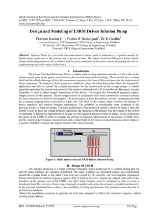
  • 5. Design And Modeling Of Lsrm Driven Infusion Pump DOI: 10.9790/1676-11132935 www.iosrjournals.org 33 | Page current reference is used to get the error in current value. This is given to the hysteresis controller. The output of whose is used to generate the PWM signals required for the switching operation. Figure.4: Speed controller block The converter is provided for each phase. Two switches and two freewheeling diodes are provided in each phase. Each of the two switches in a phase operates simultaneously. After their de-energizing the energy in the winding of the phase is expended through the freewheeling diodes. This block is shown in figure 7 and the consequent energizing for the corresponding windings is shown in figure6 Figure.5: Position sensor block Figure.6: Converter topology for A Phase Figure.7: SRM with Converter The MATLAB Simulation output is as shown in figure.8
  • 6. Design And Modeling Of Lsrm Driven Infusion Pump DOI: 10.9790/1676-11132935 www.iosrjournals.org 34 | Page Figure. 8 Simulation Result IV. Conclusion In this proposed system, an Infusion Pump using a Linear Switched Reluctance Motor is implemented. The use of the switched reluctance motor eliminated the presence of the additional frictional encountered while using a stepper motor. This is done by removing the need for a transmission system to obtain the linear movement. The occurrence of oscillations in the movement of the Linear Switched Reluctance Motor is also greatly reduced by ensuring a smooth and continuous motion of the translator of the motion. Authors Profile Mr.Praveen Kumar .C is workingpresently as Assistant Professor in the Electrical and Electronics Engineering Dept. of NSS College of Engineering Palakkad. His research areas include Plasma Physics, Electric Propulsion, Mechatronics, BiomedicalDevices and Electromagnetism. Vishnu R Nedungadi is a PG Scholar currently doing his M.Tech in Power Electronics at N.S.S College of Engineering, Palakkad. His areas of interest include Power Electronics, Power Systems and Control Systems. DrKGeetha is working presently as Principal, NSS College of Engineering Palakkad. She obtained her doctoral degree in Power Electronics. Her research areas include Power Electronics and Electrical Drives. References [1] R Krishnan, Switched Reluctance Motor Drives: Modeling, Simulation, Analysis, Design, and Applications, 1st ed. Boca Raton, FL: CRC, 2001. [2] Byeong-Seok, Han-Kyung Bae, Praveen Vijayraghavan, and R. Krishnan, “Design of a linear switched reluctance machine”, IEEE Transactions on Industrial Applications, Vol. 33, No. 3, November/December 2000, pp.1571-1580. [3] Bae, Han-Kyung, Byeong-Seok Lee, Praveen Vijayraghavan, and R. Krishnan, “Linear switched reluctance motor: converter and control”, in Conf. Rec. of the 1999 IEEE IAS Ann. Mtg., Oct. 1999, Phoenix, AZ, pp. 547–554. [4] GeBaoming, Aníbal T. de Almeida, and Fernando J. T. E. Ferreira, “Design of Transverse Flux Linear Switched Reluctance Motor”, IEEE Transactions on Magnetics, Vol. 45, No. 1, Jan 2009, pp.113-119. [5] B. S. Lee, “Linear switched reluctance machine drives with electromagnetic levitation and guidance systems.” Ph.D. thesis, The Bradley Department of Electrical and Computer Engineering, Virginia Tech., Blacksburg, VA, November 2000. [6] Seok-Myeong Jang, Ji-Hoon Park, Dae-Joon You, Han-Wook Cho, Ho-Kyung Sung “Design of High Speed Linear Switched Reluctance Motor”, Proceeding of International Conference on Electrical Machines and Systems 2007, Oct. 8~11, Seoul, Korea, pp. 1368-1671. [7] N. S. Lobo, Hong Sun Lim, R Krishnan, “Comparison of Linear Switched Reluctance Machines for Vertical Propulsion Application: Analysis, Design, and Experimental Correlation”, IEEE Transactions on Industrial Applications, Vol. 44, No. 4, July/August 2008, pp. 1134- 1142.
  • 7. Design And Modeling Of Lsrm Driven Infusion Pump DOI: 10.9790/1676-11132935 www.iosrjournals.org 35 | Page [8] MahirDursun, FatmagilKoc, “Linear switched reluctance motor control with PIC18F452 microcontroller”, Turkish Journal of Electrical Engineering & Computer Sciences, Vol.21, pp.1107-1119. [9] Antonio Eduardo Victoria, Maria, Carlos Manuel Pereira, “Design and Evaluation of Linear Switched Reluctance Actuator For Positioning Tasks”, Turkish Journal of Electrical Engineering & Computer Sciences, Vol.18, No.6, 2010. [10] Zhen Gang Sun, Nobert C Chung, Shi Wei Zhao, and Wai- Chen Gan, “Magnetic Analysis of Switched Reluctance Actuators in Levitated Linear Transporters”, IEEE Transactions on Vehicular Technology, Vol.59, No.9, Nov.2010, pp.4280- 4288. [11] Shi Wei Zhao, Norbert C. Cheung, Wai-ChuenGan, and Zhen Gang Sun, “A Novel Flux Linkage Measurement Method forLinear Switched Reluctance Motors”, IEEE Transactions on Instrumentation and Measurement”, Vol.58, No.10, October 2009, pp.3569-3575. [12] J. F. Pan, Yu Zou, and Guangzhong Cao, “An Asymmetric Linear Switched Reluctance Motor”, IEEE Transactions on Energy Conversion, Vol.28, No.2, June 2013, pp.444-451. [13] Shi Wei Zhao, Norbert C. Cheung, Wai-ChuenGan, and Jin Ming Yang, “High-Precision Position Control of a Linear- SwitchedReluctance Motor Using a Self-Tuning Regulator”, IEEE Transactions on Power Electronics, Vol.25, No.11, Novemnber 2010, pp. 2820-2827. [14] MahirDursun and SemihOzden, “Design of Monitoring System for Linear Switched Reluctance Motor with Quadrature Encoder and Current Sensors”, International Journal of Computer Theory and Engineering,Vol. 5, No. 3, June 2013, pp. 401-404. [15] Amanda, M.S. 2001. “Design and Implementation of A Novel Single- phase Switched Reluctance Motor Drive System”. M.Sc. Thesis, Virginia Polytechnic Institute and State University, Blacksburg, Virginia. [16] Arreola, R.B. 2003. “Nonlinear Control Design for a Magnetic Levitation System”.M.Sc. Thesis, University of Toronto, Canada. [17] W. C. Gan, N. C. Cheung, and L. Qiu, “Position Control of Linear Switched Reluctance Motors for High-precision Applications”, IEEE Trans. Ind. Applicat., Vol. 39, No. 5, pp. 1350-1362, Sept/Oct. 2003. [18] T.J.E. Miller, Electronic Control of Switched Reluctance Machines, Oxford, U.K., Newnes, 2001. [19] G. Song, H. Sun, L. Huang, and J. Chu, “Micro-step Position Control of Switched Reluctance Motors”, In Proc. Conf. PEDS 2003, Vol. 2, pp. 944-947, Nov. 2003. [20] M. H. Kim, W. S. Baik, D. H Kim and K. H. Choi, “AHigh Performance Position Control System of Switched Reluctance Motor”, in Proc. Conf. PCC ’07, pp. 249-252, Nagoya, April 2007 [21] C. Mademlis and I. Kioskeridis, “Four-quadrant Smooth Torque Controlled Switched Reluctance Machine Drives”, Conf. Proc. IEEE-PESC-08, Rhodos, Greece, June 2008. [22] C. Mademlis and I. Kioskeridis, “Performance Optimization in Switched Reluctance Motor Drives with Online Commutation Angle Control”, IEEE Trans. Energy Conversion, Vol. 18, pp. 448-457, Sept. 2003