TrustArc Webinar - Stay Ahead of US State Data Privacy Law Developments
D012473845
1. IOSR Journal of Mechanical and Civil Engineering (IOSR-JMCE)
e-ISSN: 2278-1684,p-ISSN: 2320-334X, Volume 12, Issue 4 Ver. VII (Jul. - Aug. 2015), PP 38-45
www.iosrjournals.org
DOI: 10.9790/1684-12473845 www.iosrjournals.org 38 | Page
CFD Analysis of Flue Gases over Valve Spindle with Rotor Wings
in 2 Stroke Marine Diesel Engines
Vishal Vinodkumar1
, Vineet Nair 2
1
(Mechanical Engineering, SIES Graduate School of Technology, India)
2
(Mechanical Engineering, SIES Graduate School of Technology, India)
Abstract : Earlier in ships, the exhaust valves in 2 stroke diesel engines were actuated by a mechanism,
controlled by rocker arms and camshaft. But due to weight and space constraints of the diesel engines of ships,
the camshaft and huge rocker arms have been replaced by hydraulic power pack to actuate the valve. As a
design modification, rotor wings were also attached to the exhaust valve spindles. When the exhaust valve
opens, the exhaust gas rotates the wings and turns the spindle by a certain degree. In this paper, a study about
how these rotors extend the lifeline of the spindles has been carried out. The paper outlines the various analyses
conducted on the existent spindle design, the boundary conditions input to the software and the various results,
namely temperature and pressure variation graphs, and moment reaction acting on the spindle. It also compiles
an analysis of how the rotor wings have been modified to attempt to extend the lifeline of the spindles through
computational fluid dynamics (CFD) and a comparison of the test results for various designs has been included.
Keywords: Computational fluid dynamics(CFD), exhaust gas, finite element analysis(FEA), rotor wings, time
between overhauling(TBO), valve spindles
I. Introduction
During the exhaust stroke of two stroke marine diesel engines, the flue gases are emitted at very high
pressure resulting in back pressure acting only on a part of the valve spindle, once it lowers from its seat.
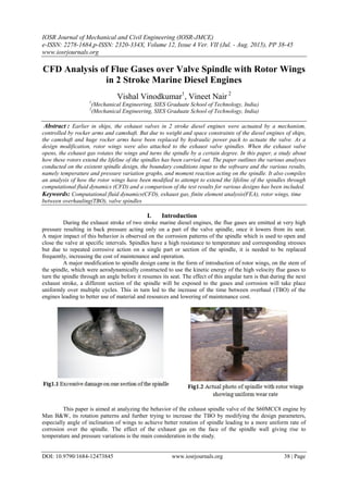
A major impact of this behavior is observed on the corrosion patterns of the spindle which is used to open and
close the valve at specific intervals. Spindles have a high resistance to temperature and corresponding stresses
but due to repeated corrosive action on a single part or section of the spindle, it is needed to be replaced
frequently, increasing the cost of maintenance and operation.
A major modification to spindle design came in the form of introduction of rotor wings, on the stem of
the spindle, which were aerodynamically constructed to use the kinetic energy of the high velocity flue gases to
turn the spindle through an angle before it resumes its seat. The effect of this angular turn is that during the next
exhaust stroke, a different section of the spindle will be exposed to the gases and corrosion will take place
uniformly over multiple cycles. This in turn led to the increase of the time between overhaul (TBO) of the
engines leading to better use of material and resources and lowering of maintenance cost.
This paper is aimed at analyzing the behavior of the exhaust spindle valve of the S60MCC8 engine by
Man B&W, its rotation patterns and further trying to increase the TBO by modifying the design parameters,
especially angle of inclination of wings to achieve better rotation of spindle leading to a more uniform rate of
corrosion over the spindle. The effect of the exhaust gas on the face of the spindle wall giving rise to
temperature and pressure variations is the main consideration in the study.
2. Cfd Analysis Of Flue Gases Over Valve Spindle With Rotor Wings In 2 Stroke Marine Diesel Engines…
DOI: 10.9790/1684-12473845 www.iosrjournals.org 39 | Page
II. Review of literature
The study done by Dr.Ing Holler Fellman [1] gave a detailed description of the different wear
mechanisms the spindle valve undergoes. Based on the paper being discussed, adhesion and abrasive wear was
found at the valve drive, air cylinder and valve spindle stem. Build-up of deposits in valve spindle guides results
in non-symmetric thermal load which leads to “Cobble stone corrosion” and cracks that start under the head
radius resulting in a catastrophic failure follows, with parts of the spindle dropping into the combustion
chamber. The temperature range shown below will be used as a validation for the results obtained from the CFD
analysis conducted further.
III. Report on present investigation
3.1 Methodology Adopted
3.1.1 Modelling
The modeling of the specimen spindle with rotor wings was done on SolidWorks. SolidWorks [2] is a
3D mechanical CAD (computer-aided design) program that runs on Microsoft Windows and is being developed
by Dassault Systems SolidWorks Corp., a subsidiary of Dassault Systems. SolidWorks is a Para solid-based
solid modeler, and utilizes a parametric feature-based approach to create models and assemblies. The spindle
and rotor wings were modelled separately and then assembled together. The final assembly was ready after 3
major iterations, taking into consideration the measurements, which were obtained from the industry where the
specimen was available and also after adding material to the model.
3.1.2 Analysis
Computational Fluid Dynamics (CFD) uses numerical methods and algorithms to solve and analyze
problems that involve fluid flows. Computers are used to perform the calculations required to simulate the
interaction of liquids and gases with surfaces defined by boundary conditions. The Navier stokes equation in
Cartesian co-ordinates were selected as governing equation of the given problem and for desired results, we
used Fluid Structure Interaction System (FSI).FSI is the interaction of some movable or deformable structure
with an internal or surrounding fluid flow. FSI can be stable or oscillatory. In this study, for FSI setup we have
used ANSYS CFX and ANSYS Static Structural on ANSYS Workbench 2.0, ANSYS 15.0.7 [3]. The first half,
where the flow pattern and its temperature and pressure effects on the spindle wall is to be generated has been
done using ANSYS CFX and the latter half, where the effect of flow on rotation of spindle is being studied has
been done on ANSYS Static Structural.
3. Cfd Analysis Of Flue Gases Over Valve Spindle With Rotor Wings In 2 Stroke Marine Diesel Engines…
DOI: 10.9790/1684-12473845 www.iosrjournals.org 40 | Page
3.2 CFX Setup
3.2.1 Geometry & Meshing
The geometry was imported and the spindle was suppressed to concentrate only on the fluid domain.
The inlet, outlet, cage and spindle wall were defined for ease of location in the further part of the analysis. A
grid independence test was carried out with a hex dominant mesh with body sizing of 10mm, 5mm and 3.5 mm.
We found that 3.5mm mesh gave us the optimum result with 15.5 lakh elements and the further tests were
carried out.
3.2.2 Setup
3.2.2.1. Domain Initialization
A user defined material named „Exhaust‟ was created with the properties of the exhaust gas. The total
energy heat transfer model was selected as energy gets converted into kinetic energy as well as transmitted to
the solid spindle. The turbulence model was selected as k-epsilon scalable as within CFX, the turbulence model
uses the scalable wall-function approach to improve robustness and accuracy when the near-wall mesh is very
fine. The scalable wall functions allow solution on arbitrarily fine near wall grids, which is a significant
improvement over standard wall functions. The temperature of exhaust gas at inlet was set at 600°C. Intensity
and eddy viscosity ratio – automatic with value of 0.02 (Ranges from .01 to .1) & 100 (Represents Laminar
flow) respectively.
Fig3.4 Domain Initialization
4. Cfd Analysis Of Flue Gases Over Valve Spindle With Rotor Wings In 2 Stroke Marine Diesel Engines…
DOI: 10.9790/1684-12473845 www.iosrjournals.org 41 | Page
3.2.2.2 Boundary Conditions
Inlet - A mass flow rate of 31.3kg/s [4] was applied with a direction normal to the boundary condition.
In turbulence model, intensity and eddy viscosity ratio was chosen with a value of 0.02 and 100 respectively.
Under the heat transfer model the total temperature was given as 600°C.
Outlet - An opening type boundary condition was defined to the outlet with an opening pressure of
2.393 bar with direction normal to boundary condition. The turbulence model as defined earlier was used. The
opening temperature was set at 350°C [4].
Cage - A no slip smooth wall type boundary was defined to the cage with an adiabatic heat transfer
model assuming that no heat transfer occurs across exhaust wall.
Spindle Wall - A no slip smooth wall type boundary was defined to the spindle wall with an adiabatic
heat transfer coefficient of 39.8W/m2°C at 600°C [5].
3.2.2.3 Solver & Output Control
The High Resolution advection scheme was used as all boundary conditions obtained were from
manuals provided by the official engine manufacturer and accuracy was a major factor to consider. A first order
turbulence numeric model was used as using the High Resolution scheme would increase the test run time. A
timescale factor of 1.1 and a convergence criteria of 1e^-10 was selected to ensure that the solution run could
complete over 1000 iterations as CFX terminates the run as soon as convergence criteria is met. The temperature
on the surface of the spindle wall was defined as the physical parameter in monitor objects. Appropriate co-
ordinates were provided.
5. Cfd Analysis Of Flue Gases Over Valve Spindle With Rotor Wings In 2 Stroke Marine Diesel Engines…
DOI: 10.9790/1684-12473845 www.iosrjournals.org 42 | Page
3.2.3 Solution
6. Cfd Analysis Of Flue Gases Over Valve Spindle With Rotor Wings In 2 Stroke Marine Diesel Engines…
DOI: 10.9790/1684-12473845 www.iosrjournals.org 43 | Page
3.2.4 Results
3.3 Static Structural Setup
The original spindle geometry with the properties of DuraNickel [5] was imported and a 10mm Hex
Dominant mesh was used to mesh the spindle. A remote displacement was applied to the entire spindle with all
degrees of freedom constrained. Pressure was imported from the CFX results and applied on the rotor wings as
load input to the static structural problem.
The momentary action was set as the required solution.
3.4 Design Modifications
To understand the effect of inclination of rotor wings with the horizontal plane, two separate models were
designed in SolidWorks. The angle of inclination of the existent rotor wings is 66.4°. This was given a rotation
of negative 6° and positive 6° in the two models respectively i.e. a total inclination of 60° and 72°
respectively.
7. Cfd Analysis Of Flue Gases Over Valve Spindle With Rotor Wings In 2 Stroke Marine Diesel Engines…
DOI: 10.9790/1684-12473845 www.iosrjournals.org 44 | Page
IV. Results & Validation
Table 4.1 Temperature, pressure and velocity for various configurations of valve spindle
From the above table and the temperature contours of the model, we can observe how the various
properties of flow, temperature and pressure change with the addition of rotor wings. Comparing the
temperature range on the spindle without rotor wings and the existing model with rotor wings for a specific
number of cycles, we find that the temperature range acting on the specific face of the spindle without rotor
wings due to the back pressure is the same as that on the entire face of the spindle with rotor wings. This results
in uniform wear on the spindle and increasing its TBO. In the modified models the temperature range is
approximately the same.
Table 4.2 Moment reactions for various configurations of valve spindle
Total Moment Reaction (N-m)
1. With Rotor Wings 209.14
2. Modified at 60° 333.9
3. Modified at 72° 195.34
Comparing the existing model‟s results to those of the model with 60° angle of inclination, it was
observed that the moment reaction has greater value for the latter. This indicates that the spindle will have a
larger degree of rotation with rotor wings inclined at 60°.
Temp Range on
Spindle Head (K)
Pressure range
On Rotor wings
(x 105
Pa)
Velocity range of Exhaust
gas at outlet (m/s)
1. Without Rotor Wings 843.4 – 984.2 - 544.4 – 975.9
2. With Rotor Wings 734.9 - 903.4 3.139 – 4.457 389.7 – 776.9
3. Modified at 60° 741.4 – 924.7 3.258 – 7.559 349.5 – 698.9
4. Modified at 72° 740.7 – 923.8 3.802 – 5.888 351 – 701.2
8. Cfd Analysis Of Flue Gases Over Valve Spindle With Rotor Wings In 2 Stroke Marine Diesel Engines…
DOI: 10.9790/1684-12473845 www.iosrjournals.org 45 | Page
Validation for velocity of exhaust gas & temperature on spindle head
The manual of the engine under consideration, S60MCC8 by Man B&W helped in providing the
necessary formulae to calculate the velocity of the exhaust gas at the desired cross-section in the exhaust cage.
The value of velocity was calculated at the outlet of the exhaust cage [4].
Mass density of gas (ρ) was expressed as;
ρ = 1.293 x 273/ (273+T) x 1.015 kg/m3
where T = 245o
C , exhaust gas temperature at specified MCR[4]
ρ = 0.685 kg/m3
Further the exhaust gas velocity (v) was calculated using the following expression;
v = (M/ρ) x 4/ (3.1415 x D2
) m/s
where D = 330 mm @ Outlet (measured at the industry where the specimen was available)
v = 31.3/0.685 x 4/ (3.1415 x 0.332
)
v = 534.239 m/s
Table 4.3 Comparison of values of exhaust gas velocity
Velocity of exhaust gas at outlet of cage (with rotor wings) in m/s
Value obtained from CFD Simulation(average) 583.3
Calculated value 534.24
From the above table, it can be seen that the simulation results are a close match with the calculated
value of the velocity of exhaust gas. This validates the boundary conditions and values given as input in the
software during CFD analysis.
Table 4.4 Comparison of values of temperature range on spindle head
Temperature range on spindle head In K
Range obtained from CFD simulation 734.9 - 903.4
Range given in study by Dr. Ing. Holler Fellman 663-903
The temperature variations obtained during the CFD simulation was in the same range as that obtained
by Dr. Ing. Holler Fellman [1] in his study, under the same conditions.
V. Conclusion
Thus, the study has been concluded, covering all points and objectives as desired. A comparative
analysis of various designs has been given for better understanding of the designing parameters. The results
achieved at the end of the project could enable further research in the same topic. The procedures used and
methodologies adopted would help future researchers determine how TBO of the ships could be increased.
There is also scope of using advanced CFD Analysis to modify various other parameters that have been used
throughout the project to help improve the efficiency of working of the spindles and further reduce the uniform
rate of corrosion over the spindle
References
[1]. Dr. Ing. Holger Fellmann, Thomas Groß, Torsten Ludwig, Typical wear mechanism of 2-stroke exhaust valves, 2004
[2]. Solidworks 2014 tutorial video http://www.solidworks.in/sw/resources/solidworks-tutorials.html
[3]. ANSYS tutorial videos http://www.mece.ualberta.ca/tutorials/ansys
[4]. MAN B&W S60MC-C8 Engine Manual, 2009, 188, 279-294
[5]. DuraNickel 301 – Special Metals, Special Metals Corporation, SMC-048, 2004.

![Cfd Analysis Of Flue Gases Over Valve Spindle With Rotor Wings In 2 Stroke Marine Diesel Engines…
DOI: 10.9790/1684-12473845 www.iosrjournals.org 39 | Page
II. Review of literature
The study done by Dr.Ing Holler Fellman [1] gave a detailed description of the different wear
mechanisms the spindle valve undergoes. Based on the paper being discussed, adhesion and abrasive wear was
found at the valve drive, air cylinder and valve spindle stem. Build-up of deposits in valve spindle guides results
in non-symmetric thermal load which leads to “Cobble stone corrosion” and cracks that start under the head
radius resulting in a catastrophic failure follows, with parts of the spindle dropping into the combustion
chamber. The temperature range shown below will be used as a validation for the results obtained from the CFD
analysis conducted further.
III. Report on present investigation
3.1 Methodology Adopted
3.1.1 Modelling
The modeling of the specimen spindle with rotor wings was done on SolidWorks. SolidWorks [2] is a
3D mechanical CAD (computer-aided design) program that runs on Microsoft Windows and is being developed
by Dassault Systems SolidWorks Corp., a subsidiary of Dassault Systems. SolidWorks is a Para solid-based
solid modeler, and utilizes a parametric feature-based approach to create models and assemblies. The spindle
and rotor wings were modelled separately and then assembled together. The final assembly was ready after 3
major iterations, taking into consideration the measurements, which were obtained from the industry where the
specimen was available and also after adding material to the model.
3.1.2 Analysis
Computational Fluid Dynamics (CFD) uses numerical methods and algorithms to solve and analyze
problems that involve fluid flows. Computers are used to perform the calculations required to simulate the
interaction of liquids and gases with surfaces defined by boundary conditions. The Navier stokes equation in
Cartesian co-ordinates were selected as governing equation of the given problem and for desired results, we
used Fluid Structure Interaction System (FSI).FSI is the interaction of some movable or deformable structure
with an internal or surrounding fluid flow. FSI can be stable or oscillatory. In this study, for FSI setup we have
used ANSYS CFX and ANSYS Static Structural on ANSYS Workbench 2.0, ANSYS 15.0.7 [3]. The first half,
where the flow pattern and its temperature and pressure effects on the spindle wall is to be generated has been
done using ANSYS CFX and the latter half, where the effect of flow on rotation of spindle is being studied has
been done on ANSYS Static Structural.](data:image/gif;base64,R0lGODlhAQABAIAAAAAAAP///yH5BAEAAAAALAAAAAABAAEAAAIBRAA7)