Fabrication of Flowerlike Polymer Microstructures Using Zeolite Composites
•Télécharger en tant que PPTX, PDF•
0 j'aime•504 vues


Recommandé
Contenu connexe
Tendances
Tendances (20)
En vedette
En vedette (9)
Similaire à Fabrication of Flowerlike Polymer Microstructures Using Zeolite Composites
Similaire à Fabrication of Flowerlike Polymer Microstructures Using Zeolite Composites (20)
Dernier
Dernier (20)
Fabrication of Flowerlike Polymer Microstructures Using Zeolite Composites
- 1. Fabrication of Flowerlike Polymer Superstructures Using Polymer/Zeolite Composites Prepared with Supercritical CO2 Yong Wang, Zhimin Liu,* Buxing Han, Junchun Li, Haixiang Gao, Jiaqiu Wang, and Jianling Zhang Center for Molecular Science, Institute of Chemistry, Chinese Academy of Sciences, Beijing, 100080, China
- 2. Introduction Recently developed: • Functional Composites: Host + Guest • Looking for specific properties. • Furthermore, the guest molecules are usually converted to target materials of desired characteristics. As an example, conducting filaments of polyaniline have been prepare. • In a 3-nm-wide hexagonal channel system of the aluminosilicate MCM-41. • It was found that the filaments have significant conductivity while encapsulated in the channels demonstrating its possibility in the application of nanometer electronic devices
- 3. • Composites sometimes are further dissolved or calcinated to remove the host materials and to liberate the structured materials consisting of guest substances. • Nanostructured materials including metals, semiconductors, polymers, carbons, and other functional materials have been fabricated through this technique.
- 4. • In the synthesis of such composites, the hosts, usually porous materials with high surface area are usually used to confine or direct the growth of the guest molecules. • Microporous zeolites. • Mesoporous molecular sieves. • But because of the size of the voids of host materials often falls into nanometer scale or even smaller, it is difficult to get a uniform distribution of guest molecules into the porosity of the host. • Therefore, it is essential to choose a proper way to include guest molecules into the host to get a high- loading and uniform distribution of guest molecules in the host.
- 5. • Conventionally, the guests are introduced into the voids of the host through ion exchange, capillary force, or gas condensation, etc., among which the wet solution route and the chemical vapor infiltration are the most frequently used. • As an alternative, a supercritical fluid (SCF) inclusion technique has been developed recently, which can provide high filling percentage. • For example, VPI-5 microporous zeolite had been used to adsorb organic compounds from SC CO2.
- 6. • The SCF phase inclusion technique is based on the fact that SCF has low viscosity, high diffusivity, near zero surface tension, and good solubility for many small organic molecules, which gives it the ability to carry small molecules into any fine spaces rapidly provided the spaces can contain them. • Especially, SC CO2 is an ideal solvent for the inclusion process as it is nontoxic, nonreactive, and relatively inexpensive. • On the basis of this principle, SC CO2 has been utilized to impregnate different additives into polymer matrix or porous materials.
- 7. • A report of a route of the fabrication of unique flowerlike polymer superstructures with uniform petals at the nanoscale is described. • In this method, polymer/zeolite composite is first prepared by loading corresponding monomer and initiator into the channels of the host zeolite with the aid of supercritical fluid, followed by thermal polymerization of monomers in the channels of the zeolite. • In this route specifically, SC CO2 was used to impregnate vinyl monomer into the micropores of zeolite with high filling, resulting in polymer/zeolite composites after polymerization of the monomers in the zeolite. • By etching the polymer/zeolite composites with HF aqueous solution, unique microflowers with polymer petals of nanoscale were obtained.
- 9. Experimental • Styrene (1.5 g) and initiator AIBN (7.5 mg) were charged into a 22 mL stainless steel autoclave. • Zeolite beads (0.7 g) were placed onto a stainless steel supporter fixed in the autoclave to prevent the zeolite from direct contacting with the liquid styrene. • The autoclave was then put into a water bath of 40.0 °C. The air in the autoclave was replaced with CO2, and more CO2 was charged up to 11.0 MPa. • The system was maintained at these conditions for 6 h. • The autoclave was then transferred into an oven of 80 °C to polymerize the encapsulated monomer for 12 h to obtain the polymer/zeolite composite. • The composite has a weight increase of about 20% due to the impregnation of the polymer and adsorption of the unreacted monomer. • The composite was then treated with 40% HF aqueous solution at 18 °C for the desiredtime.
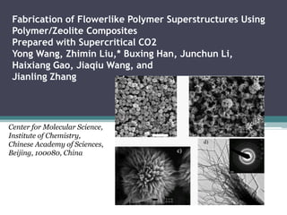
- 10. Morphology of the Materials. • In this synthesis surprisingly, flowerlike structures in microscale were formed. • Figure 1 illustrates the SEM images of PS microflowers obtained with a HF treatment time of 36 h. • We can see that the flowers are uniform in diameter and have a narrow size distribution of about 6-8micrometers.
- 11. • Every individual flower possesses many radically outextending thin petals with a thickness of about 30-60 nm, as shown in Figure 1c and d. In addition, the petals are curved in shape, indicating their flexibility. Except for some adhering contaminants, the surface is relatively smooth.
- 12. • The flowerlike structures were examined too TEM. • They are composed of thin flakes (petals), which are attached together in the center. Furthermore, we can see from the TEM images that there are some particles dispersed in the petals, which suggests that the petals are not composed of pure polymer.
- 13. • The obtained microflowers are obviously not the reflection of the channels of the zeolite because there is no such flowerlike pore structure in the zeolite. • The formation of the microflower must be formed in the HF treatment of the composites; that is, the HF etch process plays an important role in the synthesis of suchunique flowerlike structures. • Therefore, it was necessary to investigate the HF etch procedure in detail.
- 14. Characterization XDR • The PS/zeolite composite was treated with HF aqueous solution and took out some sample from the solution at intervals. • These samples were washed with copious amounts of water, dried, and then analyzed with different techniques. Evidently, the original zeolite and the polymer/ zeolite composite have almost identical XRD patterns except for the change of the relative intensity of some Bragg reflections, which strongly suggests the presence of polymer in the channels of the zeolite pores. Obviously, the HF etch drastically changes the structure of the composite. The original crystalline structure of the zeolite is severely destroyed by 5 h of HF etch, reflected by the tremendous intensity drop of the diffraction peaks.
- 15. FTRI • Zeolite characteristic peaks can be clearly seen in the spectra of the original zeolite and the PS/zeolite composite at 1005, 668, 557, and 466 cm-1,30 while after 5 h of HF etch, the intensity of the peaks drops significantly. Extending the etch time, the intensity becomes lower. At the same time, new peaks around 735 and 495 cm-1 appear, which are attributed to the newly developed Na2SiF6 crystals.
- 16. TG • TG analysis of various samples was carried out in air atmosphere up to 900 °C, and the results are given in Figure 5. • Clearly, the weight loss below 300 °C in the samples is due to the desorption of small molecules including water, and the weight loss between 300 and 390 °C on curves b, c, and d is attributed to the combustion of the PS component. • In addition, there is another weight loss above 450 °C for the two HF etched samples, resulting from the decomposition of Na2SiF6 which releases SiF4 gas. • Evidently, the weight percent of PS in the samples increases with increasing etching time, indicating the continuous dissolution of the inorganic component and the formation of the microflowers. • However, there is still inorganic component in the sample even after an etching time of 120 h, which is consistent with the result of XRD analysis. This is understandable because it takes long time for the inorganic components in the inner part to be dissolved. Therefore, we can deduce that the petals of the microflower are composed mainly of the insoluble polymer, while the center part is the inorganic/polymer core. The size of the core depends on the etch time.
- 18. N2 Adsorption • The specific surface area determined was about 20 m2/g. • The relative low BET surface area further supports the argument that, as discussed above, there was an inorganic/polymer core in the center part of a microflower.
- 19. Morphology Evolution of the System in the HF Etch Process SEM • The morphology of the polymer/zeolite composite treated with HF was examined at different times under SEM.
- 20. TEM • When examining the Na2SiF6 crystals under TEM, it was found that structures first appeared as completely dark, as shown in Figure 8a. • However, after the crystals were exposed to the electron beam for about 20 s, they presented as a much looser structure with uneven density distribution through the crystals (Figure 8b). • It is speculate that this may result from the depletion of the polymer on the Na2SiF6 crystals under the attack of the electron beam irradiation because the polymer on the crystals is much more sensitive to electron beam than the inorganic component.
- 21. Microflowers of others Polymers • Using methyl methacrylate (MMA) or divinylbenzene (DVB) as the precursor monomer and via the same procedures as were used to prepare PS microflowers, we also prepared flowerlike structures (Figure 9). This indicates that the present method is a versatile route to prepare polymer of flowerlike structure at suitable conditions. • Comparing Figures 1 and 9, it can be seen that the microflowers of different polymers have different morphologies.
- 22. • On the basis of the above characterization and analysis, it was proposed a possible mechanism of the formation of the microflowers. • With the aid of SC-CO2, the resulted polymer distributes uniformly in the zeolite, which is supported by the fact that the original zeolite can dissolve in HF aqueous solution within 10 min, while the composite can exist for much longer time at the same condition as discussed above. • During the treatment of polymer/zeolite composite with HF aqueous solution, HF and water molecules penetrate into the composite and react with the zeolite to generate species such as Na+, SiF6 2-. • However, a relatively long time is needed both for the inorganic species to diffuse into the bulk solution from the composite, and for H+ and F- in the bulk solution to diffuse into the composite because the polymer in the composite prevents their faster diffusion. • In addition, the solubility of Na2- SiF6 in water is relatively low.32 Therefore, supersaturation is reached soon, and the Na+ and SiF6 2- precipitate in the form of Na2SiF6 crystals. Meanwhile, the confined PS is liberated.
- 23. • The polymer and Na2SiF6 nearby have a strong tendency to assemble, respectively, to form aggregates with alternate polymeric and inorganic layers during this process, as is also evidenced by Figure 8. • The driving force for the assembly of the polymeric and inorganic component, respectively, is the great difference between their physicochemical natures. • With the extension of HF treating time, the Na2SiF6 layers gradually dissolve and diffuse into the bulk solution, and, due to the insoluble nature of the polymer in HF solution, the polymeric layers are retained, and the flower petals are formed by reorganization of the polymer layers as the NaSiF6 nearby is dissolved slowly. • Our experiments showed that if the composite was treated at higher temperature (e.g, 50 °C) or with stirring, flowerlike structure could not be obtained. • The reason may be that under these conditions, Na+, SiF6 2- produced from the reaction of HF with zeolite can diffuse into the bulk solution with a faster speed. Therefore, supersaturation cannot be reached and the crystallization of Na2SiF6 cannot occur, or it is dissolved quickly after formation. • We also carried out experiments in which styrene was filled in the zeolite host by immersing the host in the liquid monomer and kept the other conditions the same as above, and the microflowers could not be obtained, suggesting that SC CO2-aided impregnation of the monomer into the host is important to obtain the well-developed microflowers because SC CO2 can disperse the precursor throughout the zeolite uniformly due to its high diffusivity and near zero surface tension.
- 24. Conclusions • Unique microscale flowerlike polymer superstructures with uniform petals in nanoscale have been fabricated using zeolite as the porous host. • In this method, a polymer/zeolite composite is first prepared with the aid of SC CO2. • Subsequent HF solution treatment of the composites results in self- assembling of the polymer and inorganic components to form alternate polymeric and inorganic layers. • Further HF treatment removes the inorganic layers and leaves the polymer layers in a flowerlike structure.