1. This journal is c the Owner Societies 2013 Phys. Chem. Chem. Phys., 2013, 15, 17947--17961 17947
Cite this: Phys.Chem.Chem.Phys.,2013,
15, 17947
Effect of structural fluctuations on charge carrier
mobility in thiophene, thiazole and thiazolothiazole
based oligomers†
K. Navamani, G. Saranya, P. Kolandaivel and K. Senthilkumar*
Charge transport properties of thiophene, thiazole and thiazolothiazole based oligomers have been
studied using electronic structure calculations. The charge transport parameters such as charge transfer
integral and site energy are calculated through matrix elements of Kohn–Sham Hamiltonian. The
reorganization energy for the presence of excess positive and negative charges and rate of charge
transfer calculated from Marcus theory are used to find the mobility of charge carriers. The effect of
structural fluctuations on charge transport was studied through the polaron hopping model. Theoretical
results show that for the studied oligomers, the charge transfer kinetics follows the static non-Condon
effect and the charge transfer decay at particular site is exponential, non-dispersive and the rate coefficient
is time independent. It has been observed that the thiazole derivatives have good hole and electron
mobility.
1. Introduction
Organic semiconducting materials are widely studied for use in
organic light-emitting diodes (OLEDs),1,2
organic field effect
transistors (OFETs)3–5
and organic photovoltaic cells (OPVs)6,7
because of their potential advantages such as mechanical
flexibility, low cost and easy fabrication. During the past several
years, much research has been carried out on organic semi-
conductor materials both at experimental and theoretical
levels.8–13
In particular, oligothiophenes14–17
and oligoacenes18–20
have been extensively investigated due to their high charge carrier
mobilities. The development of n-type organic semiconductor
lags behind the p-type materials due to their instability in air
conditions and lower charge carrier mobility.21–23
Therefore, the
design and fabrication of high-performance and ambient-stable
n-channel materials is crucial for the development of organic
electronic devices such as organic p–n junctions, bipolar transistors
and integrated circuits.
Oligothiophenes are good p-type semiconductors and exhibit
high hole mobility in thin-film OFETs. These molecules have
relatively high HOMO energy levels, which lead to poor air-stability
and low current on/off ratios.24
This problem can be overcome by
introducing planar electron-accepting heterocycles in the oligomer
which could reduce the air oxidation, improve the electron
transport property and down shift the HOMO energy level.25,26
In an earlier study, Facchetti et al.27,28
have shown that
the substitution of perfluoroalkyl groups induces the n-type
semiconducting behavior in thiophene oligomers. Previously,
Gundlach et al.29
and Meng et al.30
reported that planar
molecules have a high charge transfer integral and less reorganiza-
tion energy which are the essential criteria for high performance
OFETs. Current interest in the multi-cyclic rigid like fused
p-conjugated aromatic molecules has grown, because of their
improved stability and planarity which reduce the band gap and
improve charge transport ability.31
Introduction of electron-
withdrawing moieties into p-conjugated molecules lower the
LUMO energy.26
The earlier studies showed that the presence
of electron-deficient nitrogen containing azine and azole fragments
in thiophene based oligomers improve the electron transporting
ability and reduce the threshold voltage in FET devices.25,26
Thiazole is a well-known molecule in the azole family and
has electron-deficient properties due to the presence of the
electron-withdrawing nitrogen replacing the carbon atom at the
3rd position of thiophene.32
Replacement of thiophene with
thiazole in p-conjugated system tends to lower both HOMO and
LUMO energy levels.26
The presence of thiazole rings in thio-
phene based oligomers can reduce steric interactions leading to
the planar structure.33
The electron affinity increases with the
increase of thiazole rings34
and the fused thiazole rings have a
rigid planar structure that lead to strong p–p interactions, less
structural relaxation following the introduction of extra charge
and a small HOMO–LUMO energy gap.34,35
Thiazole–thiophene
and thiazolothiazole–thiophene copolymers act as donor–acceptor
Department of Physics, Bharathiar University, Coimbatore-641 046, India.
E-mail: ksenthil@buc.edu.in
† Electronic supplementary information (ESI) available. See DOI: 10.1039/
c3cp53099j
Received 23rd July 2013,
Accepted 3rd September 2013
DOI: 10.1039/c3cp53099j
www.rsc.org/pccp
PCCP
PAPER
Publishedon04September2013.DownloadedbyBharathiarUniversityon26/05/201512:59:53.
View Article Online
View Journal | View Issue
2. 17948 Phys. Chem. Chem. Phys., 2013, 15, 17947--17961 This journal is c the Owner Societies 2013
compounds due to the presence of the CQN bond which converts
p-type into n-type semi-conducting characteristics.25,26,36–39
Previous studies show that the introduction of a thiazole ring
in oligothiophenes with trifluromethylphenyl as the substitution
group improves the electron transporting ability.25,26,40
McCullough
et al.41–43
have achieved good FET performance by combining
thiophene and thiazolothiazole (fused thiazole units) molecules.
Ando et al.33–35,44
synthesized a set of thiophene (T1, T2), thiazole
(TZ1–TZ5) and thiazolothiazole (TZTZ1–TZTZ3) oligomers and
studied the opto-electronic properties. In the above study the
trifluoromethylphenyl substitution group is used to improve
the n-type semiconducting property of the studied oligomers.
The experimental studies reveal that the studied oligomers
(T1 and T2, TZ1–TZ5 and TZTZ1–TZTZ3) have a p-stacking
structure with columnar motif which favors the transport of
charge carriers.33–35
The X-ray crystallographic studies show
that these oligomers are having sufficient planarity that is
inherently favorable for large charge transfer integral and less
reorganization energy.34,35
The inter-molecular distance
through p-stacking in TZTZ1, TZTZ2 and T1 oligomers is
3.53 Å,35
and in TZTZ3 oligomer the inter-molecular distance
is 3.59 Å.33
The thiazole oligomers TZ1–TZ5 and thiophene
oligomer T2 are having inter-molecular p-stacking distance of
3.37 Å.34
The LUMO energy of these oligomers is nearer to the
work function of metals such as magnesium and aluminum
that support the fabrication of high performance n-type semi-
conducting devices.34,45,46
The chemical structure of these
p-conjugated oligomers T1, T2, TZ1–TZ5, TZTZ1, TZTZ2 and
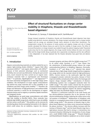
TZTZ3 is shown in Fig. 1.
It has been shown that the FET mobility depends on the
substrate used and temperature of the deposition. For thiophene
oligomer T1, the mobility increases from 0.07 to 0.18 cm2
VÀ1
sÀ1
as the temperature increases from 25 1C to 50 1C on the SiO2
substrate. At room temperature, thiazole oligomer TZ1 has FET
mobility of 0.21, 0.52 and 1.83 cm2
VÀ1
sÀ1
with the substrates
SiO2, HMDS and OTS, respectively. It has been found that the
oligomer TZ1 has good mobility but no FET characteristics are
reported for its structural isomer, TZ2. The position of S and N
atoms in the isomers determines the planarity of the molecule
and FET performance. Also, the isomers TZ4 and TZ5
have different mobility values. The FET mobility in TZ4 is
0.085 cm2
VÀ1
sÀ1
, whereas the mobility of charge carrier in
TZ5 is 0.018 cm2
VÀ1
sÀ1
at room temperature in the SiO2
substrate. The position of thiophene and thiazole rings in the
isomers TZ4 and TZ5 is responsible for their FET performance.
Among the thiazolothiazole oligomers, TZTZ2 has the maximum
charge carrier mobility of 0.12, 0.30 and 0.26 cm2
VÀ1
sÀ1
at the
temperatures 25, 50 and 100 1C, respectively, on the SiO2
substrate. The FET mobility is not observed in TZTZ1. Therefore,
to understand the charge transport properties of these mole-
cules, one of the most important tasks is studying the electronic
properties of these molecules at a molecular level through the
key parameters of charge transport such as site energy, charge
transfer integral, reorganization energy and the effect of struc-
tural fluctuations on these parameters which determine the rate
of charge transfer and mobility.
In the present study, a method proposed by Siebbeles and
co-workers47
based on the fragment molecular orbital (FMO)
Fig. 1 The chemical structure of thiophene, thiazole and thiazolothiazole based
oligomers.
Paper PCCP
Publishedon04September2013.DownloadedbyBharathiarUniversityon26/05/201512:59:53.
View Article Online
3. This journal is c the Owner Societies 2013 Phys. Chem. Chem. Phys., 2013, 15, 17947--17961 17949
approach has been used to calculate the charge transfer integral
(also called electronic coupling or hopping matrix element) and
site energy for hole and electron transport in these molecules.
Further, these values are used to calculate the rate of charge
transfer and carrier mobility. The molecular dynamics (MD)
simulations were performed to study the structural fluctuations
in the form of stacking angle in the studied oligomers. In order
to study the polaronic effect on the charge carrier mobility,
Monte-Carlo (MC) simulations were performed.
2. Theoretical methodology
By using tight binding Hamiltonian approach the presence of
excess charge in a p-stacked molecular system is expressed as48,49
^H ¼
X
i
eiðyÞai
þ
ai þ
X
j 4 i
Ji;jðyÞai
þ
aj (1)
where, ai
+
and ai are creation and annihilation operators, ei(y) is
the site energy, energy of the charge when it is localized at ith
molecular site and is calculated as diagonal element of the
Kohn–Sham Hamiltonian, ei = hji|HˆKS|jii, the second term of
eqn (1), Ji, j is the off-diagonal matrix element of Hamiltonian,
Ji, j = hji|HˆKS|jji known as charge transfer integral or electronic
coupling, which measures the strength of the overlap between
ji and jj (HOMO or LUMO of nearby molecules i and j ).
Within the semi-classical Marcus theory, the rate of charge
transfer (KCT) is determined using the reorganization energy (l)
and effective charge transfer integral ( Jeff)50–52
KCT ¼
Jeff
2
ðyÞ
h
p
lkBT
1=2
exp À
l
4kBT
(2)
where kB is the Boltzmann constant and T is the temperature
(here T = 298 K). Here, Jeff is dependent on the stacking angle (y)
between the adjacent molecules. The stacking angle is the
mutual angle between two p-stacked molecules, where the
center of mass is the center of rotation. The generalized or
effective charge transfer integral is defined in terms of charge
transfer integral (J), spatial overlap integral (S) and site energy
(e) as,53
Jeffð Þi;j¼ Ji;j À Si;j
ei þ ej
2
(3)
where, ei and ej are the energy of a charge when it is localized at
ith and jth molecules, respectively. The site energy, charge
transfer integral and spatial overlap integral were computed
using the fragment molecular orbital (FMO) approach as
implemented in the Amsterdam Density Functional (ADF)
theory program.47,54,55
In ADF calculation, we have used the
Becke–Perdew (BP)56,57
exchange correlation functional with
triple-z plus double polarization (TZ2P) basis sets. For comparison
purposes, for a few oligomers, the ADF calculations were per-
formed with correct asymptotic behavior type exchange correlation
functional statistical average of orbital potentials (SAOP).58,59
In
these methods, the charge transfer integral and site energy are
calculated directly from the Kohn–Sham Hamiltonian.47,48
Here
the charge transfer integral and site energy are calculated without
invoking the assumption of zero spatial overlap integral, and it
is not necessary to apply an electric field to bring the site energy
of the molecules into resonance.55
In the present work, the
calculations were carried out for different stacking angles.
The reorganization energy measures the change in energy of the
molecule due to the presence of excess charge and the surrounding
medium. The reorganization energy for the presence of excess
hole (positive charge, l+) and electron (negative charge, lÀ) is
calculated as,60,61
lÆ = [EÆ
( g0
) À EÆ
( gÆ
)] + [E0
( gÆ
) À E0
( g0
)] (4)
where, EÆ
( g0
) is total energy of an ion in neutral geometry,
EÆ
( gÆ
) is the energy of an ion in ionic geometry, E0
( gÆ
) is the
energy of the neutral molecule in ionic geometry and E0
( g0
) is
the optimized ground state energy of the neutral molecule. The
geometry of the studied oligomers T1, T2, TZ1–TZ5 and TZTZ1–
TZTZ3 in neutral and ionic states are optimized using density
functional theory method (DFT), B3LYP62–64
in conjunction with
the 6-311G(2d,2p) basis set, as implemented in the Q-Chem
software package.65
In a regular static p-stacked system, the site energy disorder
is minimum and the charge transfer rate (KCT) is constant. The
mobility (m) can be calculated from the Einstein relation,
m ¼
eR2
kBT
KCT (5)
where R is the inter-molecular distance. As reported in previous
studies,55,66,67
the structural fluctuations in the form of change
in p-stacking angle strongly influence the rate of charge transfer.
In the disordered geometry, the migration of charge from one
site to another site can be explained through the incoherent
hopping charge transport mechanism. In the present study, we
have performed Monte-Carlo (MC) simulations to calculate the
charge carrier mobility in a disordered system, in which charge
is propagated on the basis of the rate of charge transfer
calculated from semi classical Marcus theory (eqn (2)).48,55
In this model, we assume that the charge transport takes
place along the sequence of p-stacked molecules and the charge
does not reach the end of molecular chain within the time scale
of simulation. In each step of Monte-Carlo simulation, the
most probable hopping pathway is found from the simulated
trajectories based on the charge transfer rate at a particular
conformation. In the case of normal Gaussian diffusion of the
charge carrier in one dimension, the diffusion constant D is
calculated from mean square displacement, hX2
(t)i which
increases linearly with time, t
D ¼ lim
t!1
X2
tð Þ
2t
(6)
The charge carrier mobility is calculated from diffusion con-
stant D by the Einstein relation,68
m ¼
e
kBT
D (7)
To get the quantitative insight on charge transport properties
in these molecules, the information about stacking angle and its
PCCP Paper
Publishedon04September2013.DownloadedbyBharathiarUniversityon26/05/201512:59:53.
View Article Online
4. 17950 Phys. Chem. Chem. Phys., 2013, 15, 17947--17961 This journal is c the Owner Societies 2013
fluctuation from equilibrium is required. To get this information
the molecular dynamics simulation for stacked dimer was
performed using TINKER 4.2 molecular modeling package69,70
with standard molecular mechanics force field, MM3.71,72
The
simulations were performed up to 10 ns with time step of 1 fs
and the atomic coordinates in trajectories were saved in intervals
of 0.1 ps. The energy and occurrence of a particular conformation
were analyzed in all the saved 100 000 frames to find the stacking
angle and its fluctuation from equilibrium value.
3. Results and discussion
The monomer geometry of the ten oligomers was optimized
using DFT calculations at B3LYP/6-311G(2d,2p) level of theory
and are shown in Fig. S1 (ESI†). As a reasonable approximation,
the positive charge (hole) will migrate through the highest
occupied molecular orbital (HOMO) and the negative charge
(electron) will migrate through the lowest unoccupied molecular
orbital (LUMO) of the stacked oligomers. The charge transfer
integrals, spatial overlap integrals and site energies corres-
ponding to positive and negative charges were calculated based
on coefficients and energies of HOMO and LUMO. The density
plot of HOMO and LUMO of the studied oligomers calculated at
B3LYP/6-311G(2d,2p) level of theory is shown in Fig. 2 and 3,
respectively. As shown in Fig. 2 and 3, the HOMO and LUMO are
p orbitals and are delocalized mainly on the thiazolothiazole,
thiazole and thiophene rings and possess less density on the end
substituted trifluoromethylphenyl groups. It has been observed
that the introduction of a thiazole group enhances the electron
density delocalization on the LUMO.
3.1. Effective charge transfer integral
The effective charge transfer integral ( Jeff) for hole and electron
transport in thiophene, thiazole and thiazolothiazole derivatives
are calculated using eqn (3) and are summarized in Tables 1 and 2
and Tables S1 and S2 (ESI†). In agreement with an earlier study,47
the calculated results show that both Becke–Perdew (BP) and
statistical average of orbital potentials (SAOP) exchange correla-
tion functionals provide similar results. The variation of Jeff with
respect to stacking angle for hole and electron transport in the
studied oligomers is shown in Fig. 4 and 5, respectively. It has
been observed that the effective charge transfer integral ( Jeff) for
hole and electron transport is maximum at 01 of stacking angle.
The percentage of monomer orbital contribution for electronic
coupling in a dimer system is calculated using a fragment orbital
approach and is summarized in Tables S3 and S4 (ESI†). At 01 of
stacking angle, the HOMO of the dimer consists of 50% of
HOMO of each monomer, and the LUMO of the stacked dimer
consists of LUMO of each monomer with equal contribution
which leads to orbital overlapping in same phase.
For hole transport, among the thiophene derivatives, T2 has
maximum Jeff value of 0.34 eV at 01 of stacking angle because of
better planarity of T2 than T1. At larger stacking angles, T1 has
slightly higher Jeff than T2 for both hole and electron transport.
This is due to the fact that at the larger stacking angles, the
overlap between frontier orbitals (HOMO or LUMO) of the
studied T1 monomer is larger than that of T2, which is
Fig. 2 Highest Occupied Molecular Orbitals (HOMO) of the studied thiophene, thiazole and thiazolothiazole based oligomers.
Paper PCCP
Publishedon04September2013.DownloadedbyBharathiarUniversityon26/05/201512:59:53.
View Article Online
5. This journal is c the Owner Societies 2013 Phys. Chem. Chem. Phys., 2013, 15, 17947--17961 17951
associated with the relatively strong delocalized nature of
HOMO (or LUMO) at the middle thiophene rings of T1 oligo-
mer [see Fig. 2 and 3]. Thiazole (TZ) derivatives, TZ1–TZ5 are
having almost similar Jeff value of 0.34 eV at 01 of stacking
angle. The presence of the thiazole unit and the position of the
thiazole and thiophene units do not significantly affect the
Fig. 3 Lowest Unoccupied Molecular Orbitals (LUMO) of the studied thiophene, thiazole and thiazolothiazole based oligomers.
Table 2 Effective charge transfer integral, Jeff (in eV) at different stacking angle y (in degree) for electron transport
Stacking angle (y) in degree
Effective charge transfer integral ( Jeff) in eV
Thiophene derivatives Thiazole derivatives Thiazolothiazole derivatives
T1 T2 TZ1 TZ2 TZ3 TZ4 TZ5 TZTZ1 TZTZ2 TZTZ3
0 0.248 0.333 0.392 0.268 0.401 0.383 0.364 0.282 0.268 0.301
15 0.151 0.167 0.227 0.157 0.194 0.157 0.227 0.174 0.132 0.155
30 0.031 0.037 0.092 0.084 0.103 0.143 0.120 0.041 0.047 0.041
45 0.051 0.075 0.048 0.079 0.059 0.077 0.052 0.044 0.003 0.004
60 0.156 0.134 0.087 0.135 0.080 0.042 0.082 0.110 0.061 0.064
75 0.169 0.160 0.149 0.179 0.127 0.102 0.135 0.064 0.033 0.039
90 0.161 0.147 0.173 0.180 0.148 0.134 0.157 0.001 0.005 0.000
Table 1 Effective charge transfer integral, Jeff (in eV) at different stacking angle, y (in degree) for hole transport
Stacking angle (y) in degree
Effective charge transfer integral ( Jeff) in eV
Thiophene derivatives Thiazole derivatives Thiazolothiazole derivatives
T1 T2 TZ1 TZ2 TZ3 TZ4 TZ5 TZTZ1 TZTZ2 TZTZ3
0 0.275 0.343 0.336 0.347 0.336 0.347 0.344 0.254 0.261 0.270
15 0.199 0.243 0.267 0.255 0.217 0.241 0.219 0.214 0.178 0.166
30 0.110 0.100 0.167 0.130 0.087 0.134 0.080 0.152 0.097 0.073
45 0.051 0.042 0.088 0.031 0.012 0.051 0.014 0.106 0.064 0.047
60 0.040 0.020 0.039 0.008 0.014 0.008 0.012 0.093 0.058 0.045
75 0.027 0.017 0.015 0.007 0.012 0.010 0.011 0.048 0.033 0.026
90 0.027 0.015 0.0003 0.003 0.000 0.016 0.0005 0.041 0.030 0.025
PCCP Paper
Publishedon04September2013.DownloadedbyBharathiarUniversityon26/05/201512:59:53.
View Article Online
6. 17952 Phys. Chem. Chem. Phys., 2013, 15, 17947--17961 This journal is c the Owner Societies 2013
Jeff value. Among the thiazolothiazole derivatives, TZTZ3 has
maximum Jeff value of 0.27 eV. From Fig. 4, it has been observed
that the Jeff is exponentially decreasing with increase in the
stacking angle for all the studied oligomers. This is due to an
unequal contribution of HOMO of each monomer on the
HOMO of the dimer. For instance, at 301 of stacking angle,
the HOMO of the T1 dimer consists of HOMO of the
first monomer by 74% and HOMO of the second monomer
by 25%. Notably, at the stacking angle of 901, thiophene and
thiazolothiazole derivatives have a significant Jeff value. For
example, Jeff calculated for TZTZ1 dimer with 901 of stacking
angle is 0.04 eV, because, at this stacking angle the HOMO of
the dimer consists of HOMO of the first monomer by 50% and
the second monomer by 49%. But, the thiazole derivatives have
negligible Jeff value at 901 of stacking angle. This is due to the
fact that the HOMO of thiazole dimer consists of the first
monomer HOMO by 97% and the contribution of second
monomer HOMO is negligible.
Fig. 4 Effective charge transfer integral (Jeff, in eV) for hole transport in (a) thiophene, (b) thiazole and (c) thiazolothiazole derivatives at different stacking angles
(y, in degree).
Paper PCCP
Publishedon04September2013.DownloadedbyBharathiarUniversityon26/05/201512:59:53.
View Article Online
7. This journal is c the Owner Societies 2013 Phys. Chem. Chem. Phys., 2013, 15, 17947--17961 17953
In thiophene derivatives, for electron transport, T2 has a
maximum effective charge transfer integral of 0.33 eV at 01 of
stacking angle. Among the studied thiazole derivatives, TZ3 has
a maximum Jeff value of 0.4 eV for electron transport which
shows that the presence of more thiazole rings favors electron
transport. At 01 of stacking angle, the isomers TZ1 and TZ2 have
a different Jeff value of 0.39 and 0.27 eV, respectively which is
due to the position of the CQN bonds in the thiazole rings. In
the thiazolothiazole derivatives, TZTZ3 has a maximum Jeff
value of 0.3 eV at 01 of stacking angle. While increasing the
stacking angle from 01 to 301, the Jeff for electron transport is
decreased. Note that except for the TZ4 oligomer, further
increase in the stacking angle from 451 leads to an increase
in the Jeff value. At the stacking angle of 751, the calculated Jeff
value for the TZ2 dimer is found to be 0.18 eV. At 751 of stacking
angle, the LUMO of TZ2 dimer consists of LUMO of the first
monomer by 47% and LUMO of the second monomer by 52%.
From Table 2, it has been observed that thiophene and thiazole
Fig. 5 Effective charge transfer integral (Jeff, in eV) for electron transport in (a) thiophene, (b) thiazole and (c) thiazolothiazole derivatives at different stacking angles
(y, in degree).
PCCP Paper
Publishedon04September2013.DownloadedbyBharathiarUniversityon26/05/201512:59:53.
View Article Online
8. 17954 Phys. Chem. Chem. Phys., 2013, 15, 17947--17961 This journal is c the Owner Societies 2013
derivatives have significant effective charge transfer integrals at
the stacking angle of 901. Thiazolothiazole (TZTZ) derivatives
have a negligible Jeff value at the stacking angle of 901. Because
at this stacking angle the LUMO of TZTZ derivatives dimer
consist of 85–90% of LUMO of the first monomer and 10–15%
of LUMO of the second monomer. The above results show that
even at a larger stacking angle, thiophene derivatives have both
hole and electron transport ability. Whereas, the thiazole
derivatives have electron transport ability and thiazolothiazole
derivatives have hole transport ability at larger stacking angles
(see Fig. 4 and 5). These results confirm the results of earlier
studies,47,73
that the charge transfer integral corresponding to
hole and electron transport in organic molecules strongly
depends on the stacking angle and the presence of different
hetero atoms and their positions in the aromatic rings.
3.2. Reorganization energy
The presence of excess charge on a molecule will alter its
geometry. The energy change due to this structural reorganiza-
tion will act as a barrier for charge transport. The optimization
of neutral, anionic and cationic geometries of all the studied
oligomers is carried out at B3LYP/6-311G(2d,2p) level of theory
and the reorganization energies calculated using eqn (4) are
summarized in Table 3.
In thiophene derivatives, T2 has a minimum reorganization
energy of 0.31 and 0.38 eV for the presence of excess positive
and negative charge, respectively. This is because T2 oligomer
has more thiophene rings and more of a planar structure than
T1 which leads to a symmetrical charge distribution in T2
(see Fig. 2). Among the studied thiazole derivatives, TZ2 has a
maximum reorganization energy of 0.39 and 0.48 eV in the
presence of excess positive and negative charges, respectively.
By analyzing the optimized geometries of TZ2, it has been
observed that the presence of excess charge (positive or negative)
alters the C4–C3 bond length upto 0.04 Å and dihedral angles, C8–
C7–C5–C6 and S1–C2–C18–C16 up to 271 (for the numbering of
atoms see Fig. 1). For TZ3, TZ4 and TZ5 the calculated reorganiza-
tion energy value for the presence of excess positive charge is
similar (0.3 eV). Notably, TZ3 has a minimum reorganization
energy of 0.24 eV in the presence of excess negative charge. Because
the presence of more thiazole rings enhances the planarity and core
rigidity which reduces the structural relaxation due to the presence
of excess negative charge. The thiazolothiazole derivatives have a
similar reorganization energy value of 0.33 eV for the presence
of excess positive charge and TZTZ3 derivative has a minimum
reorganization energy value of 0.24 eV for the presence of excess
negative charge. The above results show that the presence of
thiazole and thiophene rings in the studied thiazole and
thiazolothiazole oligomers does not significantly alter the
reorganization energy for the presence of excess positive
charge, whereas TZ3 and TZTZ3 oligomers have a comparatively
smaller reorganization energy of 0.24 eV in the presence of
excess electrons which show the symmetrical negative charge
distribution in these oligomers and favor electron transport.
3.3. Charge carrier mobility
For a regular static sequence of stacked oligomers, the effective
charge transfer integral along the stack is equal to the Jeff values
are summarized in Tables 1 and 2. In this case, the mobility of
charge carrier can be calculated from eqn (5). The calculated
static mobility of positive and negative charges at different
stacking angle is summarized in Tables S6 and S7 (ESI†),
respectively. It is observed that a change in mobility with
respect to stacking angle is in accordance with the change in
Jeff value. The oligomer with a small reorganization energy has a
large mobility value. The static and dynamic structural disorder
in the p-conjugated system strongly affects the charge transfer
process via electronic coupling. As observed in earlier studies,55,66,74
the calculated Jeff value for hole and electron transport show that
the structural fluctuation in the form of stacking angle would
strongly affect the charge transport in studied oligomers. In the
present investigation, stacking angle fluctuation in thiophene,
thiazole and thiazolothiazole derivatives has been studied using
molecular dynamic (MD) simulations. The MD results provide the
information about stacking angle and its fluctuation from
equilibrium value. In the present study, the MD simulations
were carried out for stacked dimers with fixed intermolecular
distance of 3.53 Å for TZTZ1, TZTZ2 and T1 oligomers35
and
3.59 Å for TZTZ3 oligomer33
and 3.37 Å for TZ1–TZ5 and T2
oligomers34
using NVT ensembles at temperature 298.15 K and
pressure 10À5
Pa, as described in Section 2. The stacking angle
and potential energy of the stacked molecules in all the saved
100 000 frames were calculated and analyzed.
The graph has been plotted between the stacking angle and
number of occurrences of particular conformation with that
stacking angle. The plot for the thiazole oligomer, TZ1 is shown
in Fig. 6. Similar plots were obtained for the other studied
oligomers. It has been observed that the most probable con-
formation with particular stacking angle is to have a maximum
number of occurrences and minimum energy. The calculated
equilibrium stacking angle and corresponding effective charge
transfer integral of hole and electron transport for all the
studied oligomers are summarized in Table 4. It has been
observed that for thiophene oligomers, the most favorable
conformation occurs at the stacking angle of B181. The most
favorable conformation of TZ1 and TZ2 is around 301 and for TZ3–
TZ5 the stacking angle is around 151. The equilibrium stacking
Table 3 Reorganization energy, l (in eV) of thiophene (T1, T2), thiazole
(TZ1–TZ5) and thiazolothiazole (TZTZ1–TZTZ3) based oligomers
Oligomer
Reorganization energy (l) in eV
Hole Electron
T1 0.37 0.50
T2 0.31 0.38
TZ1 0.34 0.32
TZ2 0.39 0.48
TZ3 0.31 0.24
TZ4 0.30 0.27
TZ5 0.30 0.35
TZTZ1 0.32 0.36
TZTZ2 0.33 0.32
TZTZ3 0.33 0.24
Paper PCCP
Publishedon04September2013.DownloadedbyBharathiarUniversityon26/05/201512:59:53.
View Article Online
9. This journal is c the Owner Societies 2013 Phys. Chem. Chem. Phys., 2013, 15, 17947--17961 17955
angle for TZTZ1, TZTZ2 and TZTZ3 is 271, 211 and 261, respectively.
The force constant corresponding to stacking angle fluctuation has
been calculated by fitting the relative potential energy curve with
the classical harmonic oscillator equation. From the stacking angle
distribution (Fig. 6) it has been found that for all the studied
oligomers the stacking angle fluctuation of up to 101 is expected
from their equilibrium stacking angle value. As shown in Fig. 4
and 5, the Jeff will differ from place to place based on stacking
angle fluctuations. For this case, as described in Section 2, the
mobility of charge carrier has been calculated numerically using
Monte-Carlo simulations of polaron hopping transport.
During the Monte-Carlo simulations, the mean-square
displacement, hX2
(t)i of the charge has been monitored as a
function of time (t). The variation in hX2
(t)i with respect to time for
the TZ1 oligomer is shown in Fig. 7, and for other oligomers, the
results are shown in Fig. S2 (ESI†). For both hole and electron
transport, the hX2
(t)i increases linearly with respect to time. As
described in Section 2, the diffusion constant D for the charge
carrier is obtained as half of the slope of the line and based on the
Einstein relation (eqn (7)), the charge carrier mobility is directly
calculated from D. The calculated mobility of hole and electron in
the studied oligomers is summarized in Table 5. For all the studied
oligomers, the calculated mobility values from the Monte-Carlo
simulation is slightly larger than the mobility values calculated
for a static situation at the equilibrium stacking angle (see
Tables S6 and S7, ESI† and Table 5). The previous studies75,76
show that the non-Condon effect due to the structural fluctuation
influences the carrier mobility. That is the distortion in p-stack is
almost static in nature and fluctuation around the equilibrium
stacking angle favors charge transport.
To get further insight on charge transfer kinetics, the survival
probability P(t) is calculated. The P(t) is a measure of probability
for a charge carrier to be localized at particular site at a particular
time. The calculated survival probability for a charge carrier in
the thiazole oligomer, TZ1 is shown in Fig. 8, similar results were
obtained for the other oligomers and are shown in Fig. S2 (ESI†).
It has been observed that the survival probability decreases
exponentially with time and obeys the exponential law, P(t) =
exp(Àkt), here k is the charge transfer rate coefficient.77,78
At high temperatures (here, T = 298 K), the structural fluctuation
is fast and the corresponding disorder becomes dynamic rather
than static.79
The dynamic fluctuation effect on CT kinetics is
characterized using the rate coefficient which is defined as79
kðtÞ ¼ À
d ln PðtÞ
dt
(8)
The time evolution on CT kinetics in the tunneling regime is
studied using eqn (8). Based on this analysis, the type of
fluctuation (slow or fast) and the corresponding non-Condon
(NC) effect (kinetic or static) on CT kinetics is studied. To analyze
the NC effect, we plotted the charge transfer rate as a function of
time (see Fig. 9 and Fig. S2, ESI†, for TZ1 and other studied
oligomers) and fitted the line using the power law79
k(t) = ka
taÀ1
, 0 o a r 1 (9)
where, the rate coefficient, k was obtained from the survival
probability curve. It has been observed that the charge transfer
rate, k(t) varies slowly with respect to time. The dispersive
parameter ‘a’ is calculated by fitting the line with the above
eqn (9). The calculated dispersive parameter corresponding to
hole and electron transport in the studied oligomers are
summarized in Table 5. For all the studied oligomers the
dispersive parameter, a is nearer to 1 which revealed that the
Table 4 Equilibrium stacking angle (in degrees) calculated from molecular
dynamics simulations and the corresponding effective charge transfer integral
(in eV) of thiophene (T1, T2), thiazole (TZ1–TZ5) and thiazolothiazole (TZTZ1–
TZTZ3) based oligomers
Oligomers
Equilibrium stacking
angle (in degree)
Effective charge transfer
integral ( Jeff) in eV
Hole Electron
T1 19 0.170 0.110
T2 18 0.204 0.140
TZ1 30 0.167 0.092
TZ2 32 0.130 0.106
TZ3 19 0.180 0.186
TZ4 14 0.238 0.206
TZ5 18 0.187 0.204
TZTZ1 27 0.166 0.075
TZTZ2 21 0.152 0.100
TZTZ3 26 0.115 0.078
Fig. 6 The plot between the number of occurrence, relative potential energy with respect to stacking angle for TZ1 oligomer.
PCCP Paper
Publishedon04September2013.DownloadedbyBharathiarUniversityon26/05/201512:59:53.
View Article Online
10. 17956 Phys. Chem. Chem. Phys., 2013, 15, 17947--17961 This journal is c the Owner Societies 2013
CT kinetics evolves dominantly in the static type of non-
Condon effect (fast fluctuation). In this type of CT process,
the survival probability of charge evolves as an exponential
decrease and CT is non-dispersive and the rate coefficient is
time-independent. In this case, the self-averaging of effective
charge transfer integral is responsible for the time independent
rate coefficient and therefore the mean squared displacement
of charge carrier always increases linearly with time along the
full simulation time. The above results show that the mobility is
independent of frequency and the use of Einstein relation
(eqn (7)) to calculate the mobility of charge carriers in the
studied oligomers is valid.
By using the survival probability, P(t), the disorder drift80
can be studied through thermodynamical relation for entropy,
X
t
SðtÞ ¼ ÀkB
X
t
PðtÞ log PðtÞ (10)
X
t
SðtÞ ¼ kB
X
t
ðktÞ expðÀktÞ (11)
Fig. 7 The mean square displacement of (a) positive and (b) negative charge in TZ1 oligomer with respect to time.
Table 5 Mobility (m), disorder drift time (St), rate coefficient (k) and dispersive parameter (a) for hole and electron transport in thiophene (T1, T2), thiazole (TZ1–TZ5)
and thiazolothiazole (TZTZ1–TZTZ3) based oligomers
Oligomer
Mobility (m) in cm2
VÀ1
sÀ1
Disorder drift time (St) in fs Rate coefficient (k)a
in Â1014
sÀ1
Dispersive parameter (a)
Hole Electron Hole Electron Hole Electron Hole Electron
T1 1.10 0.13 17.89 160.91 0.515 0.066 0.92 0.75
T2 2.88 0.62 6.38 32.59 1.421 0.310 0.91 0.81
TZ1 1.36 0.61 15.22 34.82 3.195 0.338 0.92 0.80
TZ2 0.37 0.08 59.76 257.27 0.245 0.033 0.74 0.90
TZ3 2.28 4.51 8.53 4.16 1.304 2.541 0.70 0.79
TZ4 4.05 3.32 4.23 5.70 2.097 1.645 0.94 0.86
TZ5 2.63 4.51 6.26 10.30 1.291 0.857 0.92 0.90
TZTZ1 1.72 0.25 12.30 99.79 0.751 0.155 0.87 0.70
TZTZ2 1.22 0.52 15.40 38.00 0.570 0.325 0.82 0.73
TZTZ3 0.55 0.81 40.76 34.75 0.277 0.439 0.87 0.81
a
Rate coefficient also referred as charge decay rate.
Paper PCCP
Publishedon04September2013.DownloadedbyBharathiarUniversityon26/05/201512:59:53.
View Article Online
11. This journal is c the Owner Societies 2013 Phys. Chem. Chem. Phys., 2013, 15, 17947--17961 17957
where, kB is Boltzmann constant. The plot for disorder drift in
thiazole oligomer, TZ1 is shown in Fig. 10 and for other
oligomers, the results are shown in Fig. S2 (ESI†). The disorder
drift causes a time delay for the transient charge along the
tunneling regime. The disorder drift time, St is the time at
which the disorder drift is at a maximum and is calculated from
the graph. The high disorder drift time means the system is in
its equilibrium stacking angle for a longer time which
decreases the charge transfer rate and the mobility of the
charge carrier is almost equal to the static case mobility
calculated at the equilibrium stacking angle. Along with charge
carrier mobility and dispersive parameter (a), the disorder
drift time corresponding to hole and electron transport are
summarized in Table 5 and based on these values the charge
transfer in studied oligomers is discussed below.
As expected, in thiophene derivatives the mobility of the
positive charge is higher than the mobility of the electron and
T2 has a higher hole mobility of 2.88 cm2
VÀ1
sÀ1
with small
disorder drift time of 6.38 fs. By comparing the mobility values
calculated for thiazole isomers TZ1 and TZ2, it has been
observed that TZ2 has a lower hole and electron mobility of
0.37 and 0.08 cm2
VÀ1
sÀ1
. The small effective charge transfer
integral at the equilibrium stacking angle (321) and high
reorganization energy leads to a maximum disorder drift time
corresponding to hole and electron transport in the TZ2 oligomer.
In this case both the carriers strand a longer time on a particular
molecule instead of migrating due to less coupling between the
HOMO (or LUMO) states of nearby molecules. These results are in
agreement with the experimental results of Ando et al.34
It has
been shown in their studies that the FET mobility of TZ2 is
smaller than that of TZ1 by two orders of magnitude. While
comparing the mobility of charge carriers in thiazole isomers TZ3
and TZ4, it has been found that the hole mobility is maximum in
TZ4 and electron mobility is maximum in TZ3. Oligomer TZ4 has
a minimum disorder drift time of 4.23 fs for hole transport
(minimal dispersion and purely static NC effect) and has hole
mobility of 4.05 cm2
VÀ1
sÀ1
. This is because, the hole transport in
oligomer TZ4 evolves with fast fluctuation around the equilibrium
stacking angle of 141 and this angle is comparatively smaller than
that of the other studied oligomers. The electron mobility in TZ3
and TZ5 is 4.51 cm2
VÀ1
sÀ1
. The above results clearly show that
the charge carrier mobility strongly depends on the arrangement
of atoms and structural alignment of nearby oligomers. It has
been observed that increasing the number of thiophene rings
enhances the hole transport significantly. The introduction of
thiazole rings in oligothiophene promotes n-type characteristics
and introduces the ambipolar transporting ability. It has been
observed that the mobility of charge carriers in thiazolothiazole
oligomers is relatively smaller than that in thiazole oligomers.
Among the studied thiazolothiazole oligomers, TZTZ1 and TZTZ2
Fig. 8 The survival probability of (a) positive and (b) negative charge in TZ1 oligomer with respect to time.
PCCP Paper
Publishedon04September2013.DownloadedbyBharathiarUniversityon26/05/201512:59:53.
View Article Online
12. 17958 Phys. Chem. Chem. Phys., 2013, 15, 17947--17961 This journal is c the Owner Societies 2013
have hole mobility of 1.72 and 1.22 cm2
VÀ1
sÀ1
, respectively and a
corresponding disorder drift time of 12.3 and 15.4 fs.
One of the important factors that influence the charge
transport in a p-stacked system is the difference between the
site energy of nearby molecules. In the present work, the site
energy of p-stacked oligomers (e1 and e2) is calculated as the
diagonal matrix elements of the Kohn–Sham Hamiltonian and
the site-energy difference of p-stacked dimers is summarized in
Tables S8 and S9 (ESI†) at different stacking angles for positive
and negative charges. For all the studied p-stacked oligomers,
the significant difference between e1 and e2 is noted around the
equilibrium stacking angle for both hole and electron trans-
port. For thiophene oligomers, the site energy difference up to
0.06 eV was observed for hole and electron transport. Among
the thiazole oligomers, TZ1 and TZ3 have a maximum site
energy difference of B0.06 eV around the equilibrium stacking
angle for both hole and electron transport, and the oligomers
TZ2 and TZ4 have a site energy difference of B0.03 eV. The
thiazolothiazole oligomer, TZTZ2 has a relatively small site
energy difference of 0.01 eV around the equilibrium stacking
angle of 211. The site energy difference would act as a barrier
for charge transport and reduce the rate of charge transfer and
mobility. The above discussed mobility values were obtained
from Marcus rate eqn (6) and the site energy difference was not
included in the Monte-Carlo simulation for charge transport.
Hence, the reported mobility values are an upper limit and
provide qualitative information about charge transport in the
studied oligomers.
4. Conclusion
The parameters involved in the charge transport calculation
such as the charge transfer integral, site energy and reorganiza-
tion energy have been calculated for thiophene, thiazole and
thiazolothiazole based oligomers using quantum chemical
calculations. The effect of structural fluctuation in the form
of stacking angle distribution on the charge transfer rate was
studied using molecular dynamics (MD) and Monte-Carlo (MC)
simulations. It has been observed that the charge transfer
kinetics follows the static non-Condon effect due to the fast
fluctuation. In this regime, the charge transfer decay is expo-
nential, non-dispersive and the rate coefficient is time inde-
pendent due to the self-averaging of the effective charge
transfer integral. The calculated mobility of charge carriers in
TZ1 and TZ2 and also in TZ4 and TZ5 isomers shows that the
structural arrangement and position of thiophene and thiazole
rings are the crucial factors that determine the structural
planarity and efficient charge transport. Among the studied
thiazole oligomers, TZ1, TZ3, TZ4 and TZ5 have hole mobility of
1.36, 2.28, 4.05, 2.63 cm2
VÀ1
sÀ1
, respectively, and electron
mobility of 0.61, 4.51, 3.32 and 4.51 cm2
VÀ1
sÀ1
, respectively. It
has been found that the presence of thiazole rings promotes
Fig. 9 Time evolution of the rate coefficients for (a) positive and (b) negative charge transport in TZ1 oligomer.
Paper PCCP
Publishedon04September2013.DownloadedbyBharathiarUniversityon26/05/201512:59:53.
View Article Online
13. This journal is c the Owner Societies 2013 Phys. Chem. Chem. Phys., 2013, 15, 17947--17961 17959
n-type semiconducting performance. The addition of fused
bithiazole (thiazolothiazole) oligomer does not significantly
enhance the mobility of the charge carriers. The studied
thiazole oligomers TZ1 and TZ3–TZ5 have a good ambipolar
property which is useful for molecular electronics applications.
Acknowledgements
The authors thank the Department of Science and Technology
(DST), India for awarding this research project under the Fast
Track Scheme.
References
1 C. W. Tang and S. A. Vanslyke, Appl. Phys. Lett., 1987, 51,
913–915.
2 J. H. Burroughes, D. D. C. Bradley, A. R. Brown, R. N. Marks,
K. Mackay, R. H. Friend, P. L. Burns and A. B. Holmes,
Nature, 1990, 347, 539–541.
3 H. E. Katz, J. Mater. Chem., 1997, 7, 369–376.
4 H. E. Katz, A. J. Lovinger, J. Johnson, C. Kloc, T. Siegrist,
W. Li, Y. Y. Lin and A. Dodabalapur, Nature, 2000, 404,
478–481.
5 M. Shim, A. Javey, N. W. Shi Kam and H. Dai, J. Am. Chem.
Soc., 2001, 123, 11512–11513.
6 N. S. Sariciftci, L. Smilowitz, A. J. Heeger and F. Wudl,
Science, 1992, 258, 1474–1476.
7 X. Zhan, Z. a. Tan, B. Domercq, Z. An, X. Zhang, S. Barlow,
Y. Li, D. Zhu, B. Kippelen and S. R. Marder, J. Am. Chem.
Soc., 2007, 129, 7246–7247.
8 G. H. Gelinck, T. C. T. Geuns and D. M. D. Leeuw, Appl. Phys.
Lett., 2000, 77, 1487–1489.
9 A. P. Kulkarni, C. J. Tonzla, A. Babel and S. A. Jenekhe,
Chem. Mater., 2004, 16, 4556–4573.
10 A. R. Murphy and J. M. J. Frechet, Chem. Rev., 2007, 107,
1066–1096.
11 Y. Shirota and H. Kageyama, Chem. Rev., 2007, 107, 953–1010.
12 L. Wang, G. Nan, X. Yang, Q. Peng, Q. Li and Z. Shuai, Chem.
Soc. Rev., 2010, 39, 423–434.
13 Y. Geng, S.-X. Xu, H.-B. Li, X.-D. Tang, Y. Wu, Z.-M. Su and
Y. Liao, J. Mater. Chem., 2011, 21, 15558–15566.
14 D. Fichou, Handbook of Oligo and Polythiophenes, Wiley –
VCH, Weinheim, 1999.
15 Handbook of Thiophene based Materials, ed. I. F. Perepichka
and D. F. Perepichka, Wiley – VCH, Weinheim, 2009.
16 J. M. Tour, Chem. Rev., 1996, 96, 537.
17 X. Yang, L. Wang, C. Wang, W. Long and Z. Shuai, Chem.
Mater., 2008, 20, 3205.
18 J. L. Bredas, D. Beljionne, V. Coropceanu and J. Cornil,
Chem. Rev., 2004, 104, 4971.
Fig. 10 Disorder drift time for (a) hole and (b) electron transport in TZ1 oligomer.
PCCP Paper
Publishedon04September2013.DownloadedbyBharathiarUniversityon26/05/201512:59:53.
View Article Online
14. 17960 Phys. Chem. Chem. Phys., 2013, 15, 17947--17961 This journal is c the Owner Societies 2013
19 F. J. M. Z. Heringdorf, M. C. Reuter and R. M. Tromp,
Nature, 2001, 412, 517.
20 C. Kim, A. Facchetti and T. J. Marks, Science, 2007, 318,
76.
21 Q. Wu, R. Li, W. Hong, H. Li, X. Gao and D. Zhu, Chem.
Mater., 2011, 3138–3140.
22 Z. Bao, Adv. Mater., 2000, 12, 227–230.
23 Y. Geng, J. Wang, S. Wu, H. Li, F. Yu, G. Yang, H. Gao and
Z. Su, J. Mater. Chem., 2011, 21, 134–143.
24 H. E. Katz, Z. Bao and S. L. Gilat, Acc. Chem. Res., 2001,
34, 359.
25 R. P. Ortiz, H. Yan, A. Facchetti and T. J. Marks, Materials,
2010, 3, 1533.
26 Y. Lin, H. Fan, Y. Li and X. Zhan, Adv. Mater., 2012, 24, 3087.
27 A. Facchetti, M. Mushrush, H. E. Katz and T. J. Marks, Adv.
Mater., 2003, 15, 33.
28 A. Facchetti, J. Letizia, M.-H. Yoon, M. Mushrush, H. E. Katz
and T. J. Marks, Chem. Mater., 2004, 16, 4715.
29 D. J. Gundlach, Y. Y. Lin, T. N. Jackson and S. F. Nelson,
Appl. Phys. Lett., 2002, 80, 2925.
30 H. Meng, M. Bendikov, G. Mitchell, R. Helgeson, F. Wudl,
Z. Bao, T. Siegrist, C. Kloc and C. H. Chen, Adv. Mater., 2003,
15, 1090.
31 D. Pranabesh, P. Hanok, L. Woo-Hyoung, K. In-Nam and
L. Soo-Hyoung, Org. Electron., 2012, 13, 3183.
32 M. Zhang, H. Fan, X. Guo, Y. He, Z. Zhang, J. Min, J. Zhang,
G. Zhao, X. Zhan and Y. Li, Macromolecules, 2010, 43, 5706.
33 S. Ando, J. Nishida, Y. Inoue, S. Tokito and Y. Yamashita,
J. Mater. Chem., 2004, 14, 1787–1790.
34 S. Ando, R. Murakami, J. Nishida, H. Tada, Y. Inoue,
S. Tokito, S. Tokito and Y. Yamashita, J. Am. Chem. Soc.,
2005, 127, 14996–14997.
35 S. Ando, J. Nishida, H. Tada, Y. Inoue, S. Tokito and
Y. Yamashita, J. Am. Chem. Soc., 2005, 127, 5336–5337.
36 G. Xia, F. Haijun, Z. Maojie, H. Yu, T. Songting and
L. Yongfang, J. Appl. Polym. Sci., 2012, 124, 847.
37 B. Balan, C. Vijayakumar, A. Saeki, Y. Koizumi and S. Seki,
Macromolecules, 2012, 45, 2709.
38 S. Van mierloo, S. Chambon, A. E. Boyukbayram,
P. Adriaensens, L. Lutsen, T. J. Cleij and D. Vanderzande,
Magn. Reson. Chem., 2010, 48, 362.
39 T. Kono, D. Kumaki, J.-i. Nishida, S. Tokito and
Y. Yamashita, Chem. Commun., 2010, 46, 3265.
40 M. Mamada, J.-I. Nishida, D. Kumaki, S. Tokito and
Y. Yamashita, Chem. Mater., 2007, 19, 5404.
41 M. Mamada, J.-I. Nishida, S. Tokito and Y. Yamashita,
Chem. Lett., 2008, 766.
42 I. Osaka, G. Sauve, R. Zhang, T. Kowalewski and
R. D. McCullough, Adv. Mater., 2007, 19, 4160.
43 I. Osaka, R. Zhang, G. Sauve, D.-M. Smilgies, T. Kowalewski
and R. D. McCullough, J. Am. Chem. Soc., 2009, 131, 2521.
44 S. N. Ando, J. Nishida, H. Tada, Y. Inoue, S. Tokito and
Y. Yamashita, J. Am. Chem. Soc., 2005, 127, 5336–5337.
45 C. R. Newman, C. D. Frisbie, D. A. da Silva Filho,
J.-L. Bredas, P. C. Ewbank and K. R. Mann, Chem. Mater.,
2004, 16, 4436.
46 M. Stossel, J. Staudigel, F. Steuber, J. Simmerer and
A. Winnacker, Appl. Phys. A: Mater. Sci. Process., 1999,
68, 387.
47 K. Senthilkumar, F. C. Grozema, F. M. Bichelhaupt and
L. D. A. Siebbeles, J. Chem. Phys., 2003, 119, 9809.
48 F. C. Grozema and L. D. A. Siebbles, Int. Rev. Phys. Chem.,
2008, 27, 87–138.
49 E. A. Silinsh, Organic Molecular Crystals, Springer – Verlag,
Berlin, 1980.
50 R. A. Marcus, Annu. Rev. Phys. Chem., 1964, 15, 155.
51 R. A. Marcus, Rev. Mod. Phys., 1993, 65, 599.
52 M. Bixon and J. Jortner, J. Chem. Phys., 2002, 281, 393.
53 M. D. Newton, Chem. Rev., 1991, 91, 767.
54 G. Te Velde, F. M. Bickelhaupt, E. J. Baerends, C. Fonseca
Guerra, S. J. A. Van Gisbergeh, J. G. Snijders and T. Ziegler,
J. Comput. Chem., 2001, 22, 931.
55 P. Prins, K. Senthilkumar, F. C. Grozema, P. Jonkheijm,
A. P. H. J. Schenning, E. W. Meijer and L. D. A. Siebbles,
J. Phys. Chem. B, 2005, 109, 18267–18274.
56 A. D. Becke, Phys. Rev. A, 1988, 38, 3098.
57 J. P. Perdew, Phys. Rev. B: Condens. Matter Mater. Phys., 1986,
33, 8822.
58 P. R. T. Schipper, O. V. Gritsenko, S. J. A. van Gisbergen and
E. J. Baerends, J. Chem. Phys., 2000, 112, 1344.
59 O. V. Gritsenko, P. R. T. Schipper and E. J. Baerends, Chem.
Phys. Lett., 1999, 302, 199.
60 H. L. Tavernier and M. D. Fayer, J. Phys. Chem. B, 2000,
104, 11541.
61 M. M. Torrent, M. Durkut, P. Hadley, X. Ribas and C. Rovira,
J. Am. Chem. Soc., 2004, 126, 984.
62 S. H. Vosko, L. Wilk and M. Nusair, Can. J. Phys., 1980, 58,
1200–1211.
63 A. D. Becke, J. Chem. Phys., 1993, 98, 5648–5652.
64 C. T. Lee, W. T. Yang and R. G. Parr, Phys. Rev. B: Condens.
Matter Mater. Phys., 1988, 37, 785–789.
65 Y. Shao, L. F. Molnar, Y. Jung, J. Kussmann, C. Ochsenfeld,
S. T. Brown, A. T. Gilbert, L. V. Slipchenko, S. V. Levchenko,
D. P. O’Neill, R. A. DiStasio, Jr., R. C. Lochan, T. Wang,
G. J. Beran, N. A. Besley, J. M. Herbert, C. Y. Lin, T. Van
Voorhis, S. H. Chien, A. Sodt, R. P. Steele, V. A. Rassolov,
P. E. Maslen, P. P. Korambath, R. D. Adamson, B. Austin,
J. Baker, E. F. Byrd, H. Dachsel, R. J. Doerksen, A. Dreuw,
B. D. Dunietz, A. D. Dutoi, T. R. Furlani, S. R. Gwaltney,
A. Heyden, S. Hirata, C. P. Hsu, G. Kedziora, R. Z. Khalliulin,
P. Klunzinger, A. M. Lee, M. S. Lee, W. Liang, I. Lotan,
N. Nair, B. Peters, E. I. Proynov, P. A. Pieniazek, Y. M. Rhee,
J. Ritchie, E. Rosta, C. D. Sherrill, A. C. Simmonett,
J. E. Subotnik, H. L. Woodcock, 3rd, W. Zhang, A. T. Bell,
A. K. Chakraborty, D. M. Chipman, F. J. Keil, A. Warshel,
W. J. Hehre, H. F. r. Schaefer, J. Kong, A. I. Krylov, P. M. Gill
and M. Head-Gordon, Phys. Chem. Chem. Phys., 2006, 8,
3172–3191.
66 P. Prins, F. C. Grozema and L. D. A. Siebbeles, J. Phys. Chem.
B, 2006, 110, 14659–14666.
67 Y. A. Berlin, F. C. Grozema, L. D. A. Siebbeles and
M. A. Ratner, J. Phys. Chem. C, 2008, 112, 10988–11000.
Paper PCCP
Publishedon04September2013.DownloadedbyBharathiarUniversityon26/05/201512:59:53.
View Article Online
15. This journal is c the Owner Societies 2013 Phys. Chem. Chem. Phys., 2013, 15, 17947--17961 17961
68 L. B. Schein and A. R. McGhie, Phys. Rev. B: Condens. Matter
Mater. Phys., 1979, 20, 1631.
69 J. W. Ponder, TINKER: 4.2, Software tools for molecular
design, Saint Louis, Washington, 2004.
70 P. Ren and J. W. Ponder, J. Phys. Chem. B, 2003, 107, 5933.
71 J. H. Lii and N. L. Allinger, J. Am. Chem. Soc., 1989,
111, 8576.
72 N. L. Allinger, F. Yan, L. Li and J. C. Tai, J. Comput. Chem.,
1990, 11, 868.
73 G. Saranya, N. Santhanamoorthi, P. Kolandaivel and
K. Senthilkumar, Int. J. Quantum Chem., 2012, 112, 713–723.
74 P. Prins, F. C. Grozema, F. Galbrecht, U. Scherf and L. D. A.
Siebbles, J. Phys. Chem. C, 2007, 111, 11104–11112.
75 W. Zhang, W. Liang and Y. Zhao, J. Chem. Phys., 2010, 133,
1–11.
76 S. S. Skourtis, I. A. Balabin, T. Kawatsu and D. N. Beratan,
Proc. Natl. Acad. Sci. U. S. A., 2005, 102, 3552.
77 F. C. Grozema, Y. A. Berlin and L. D. A. Siebbeles, Int. J.
Quantum Chem., 1999, 75, 1009–1016.
78 F. Reif, Fundamentals of Statistical and Thermal Physics,
McGraw-Hill, 1965, ch. 12, pp. 461–490.
79 Y. A. Berlin, F. C. Grozema, L. D. A. Siebbeles and
M. A. Ratner, J. Phys. Chem. C, 2008, 112, 10988–11000.
80 S. L. Miller and D. G. Childers, Probability and Random
Processes with Applications to Signal Processing and Commu-
nications, Elsevier Inc., 2004, ch. 9, pp. 323–359.
PCCP Paper
Publishedon04September2013.DownloadedbyBharathiarUniversityon26/05/201512:59:53.
View Article Online
17. and 10−3
cm2
/(V s), respectively.29
Comparably, the molecule
2 has higher hole mobility than 1b and is in the order of 10−3
cm2
/(V s).29
The hole and electron mobilities of 1c and the
electron mobility of 2 are not reported. Therefore, to
understand the charge transport properties of these molecules,
the electronic structure and charge transport properties such as
charge transfer integral, site energy, reorganization energy, rate
of charge transfer, mobility of charge carriers, and the effects of
nuclear and electronic degrees of freedom on the charge
transfer kinetics are studied.
In the present work, the rate of charge transfer is studied in
two situations: in the first case, the charge transfer between two
identical sites with same site energy, that is, Δεij = 0; in the
second case, the charge transfer between two nonidentical sites,
that is, Δεij ≠ 0.10,17
To get better insight into charge transport
in studied molecules, we have studied the CT kinetic
parameters such as disorder drift time, effect of structural
fluctuation on charge carrier flux, and hopping conductivity.
Here, the disorder drift time is used to identify possible
intermediate regime between band transport and localized
hopping transport. In the present study, we have formulated the
density flux equation which describes the charge diffusion
nature in the localized sites (by thermal disorder), and the time
evolution of density flux provides the relation between the
hopping conductivity and transition rate. The results obtained
from the present investigation and past studies19,20,30
show that
the structural fluctuation in the form of stacking angle change
strongly alters the charge transfer kinetics. Hence, in the
present work, the classical molecular dynamics is used to study
the stacking angle distribution in the studied molecules.
2. THEORETICAL FORMALISM
By using the tight binding Hamiltonian approach, the presence
of excess charge in a π-stacked molecular system is expressed
as31,32
∑ ∑ε θ θ̂ = ++
≠
+
H a a J a a( ) ( )
i
i i i
i j
i j i j,
(1)
where ai
+
and ai are the creation and annihilation operators;
εi(θ) is the site energy, energy of the charge when it is localized
at the ith molecular site and is calculated as diagonal matrix
element of the Kohn−Sham Hamiltonian, εi = ⟨φi|ĤKS|φi⟩. The
second term of eq 1, Ji,j, is the off-diagonal matrix element of
the Hamiltonian, Ji,j = ⟨φi|ĤKS|φj⟩, known as charge transfer
integral or electronic coupling which measures the strength of
the overlap between φi and φj (HOMO or LUMO of nearby
molecules i and j). Based on the semiclassical Marcus theory,
the charge transfer rate (k) is defined as17,23,33
π
ρ=
ℏ
| |k J
2
eff
2
FCT (2)
The effective charge transfer integral Jeff is defined in terms of
charge transfer integral J, spatial overlap integral S, and site
energy ε as34
ε ε
= −
+⎛
⎝
⎜
⎞
⎠
⎟J J S
2i j i j
i j
eff , ,i j,
(3)
where εi and εj are the energy of a charge when it is localized at
ith and jth molecules, respectively. The site energy, charge
transfer integral, and spatial overlap integral were computed
using the fragment molecular orbital (FMO) approach as
implemented in the Amsterdam density functional (ADF)
theory program.30,35,36
In ADF calculation, we have used the
Becke−Perdew (BP)37,38
exchange correlation functional with
triple-ζ plus double polarization (TZ2P) basis set.39
In this
procedure, the charge transfer integral and site energy
corresponding to hole and electron transport are calculated
directly from the Kohn−Sham Hamiltonian.31,35
In eq 2, the Franck−Condon (FC) factor ρFCT measures the
weightage of density of states (DOS) and is calculated from the
reorganization energy (λ) and the site energy difference
between initial and final states, Δεij = εj − εi.
ρ
πλ
ε λ
λ
= −
Δ +⎡
⎣
⎢
⎢
⎤
⎦
⎥
⎥k T k T
1
4
exp
( )
4
ij
FCT
B
2
B (4)
The reorganization energy measures the change in energy of
the molecule due to the presence of excess charge and changes
in the surrounding medium. The reorganization energy due to
the presence of excess hole (positive charge, λ+) and electron
(negative charge, λ−) is calculated as40,41
λ = − + −±
± ± ± ±
E g E g E g E g[ ( ) ( )] [ ( ) ( )]0 0 0 0
(5)
Figure 1. Chemical structure of triazene based octupolar molecules 1
(1b: R = OC8H17; 1c: R = OCH3) and 2 (R = OC12H25).
The Journal of Physical Chemistry C Article
dx.doi.org/10.1021/jp509450k | J. Phys. Chem. C 2014, 118, 27754−2776227755
18. where E±
(g0
) is the total energy of an ion in neutral geometry,
E±
(g±
) is the energy of an ion in ionic geometry, E0
(g±
) is the
energy of the neutral molecule in ionic geometry, and E0
(g0
) is
the optimized ground state energy of the neutral molecule. The
geometries of the studied molecules 1b, 1c, and 2 in neutral
and ionic states are optimized using the density functional
theory method B3LYP42−44
in conjunction with the 6-31G(d,
p) basis set, as implemented in the GAUSSIAN 09 package.45
As reported in previous studies,19,20,30,46
the structural
fluctuations in the form of periodic fluctuation in π-stacking
angle strongly influence the rate of charge transfer. In the
disordered geometry, the migration of charge from one site to
another site can be modeled through incoherent hopping
charge transport mechanism. In the present study, we have
performed the kinetic Monte Carlo (KMC) simulation to
calculate the charge carrier mobility in which charge is
propagated on the basis of rate of charge transfer calculated
from eq 2. In this model, we assume that the charge transport
takes place along the sequence of π-stacked molecules, and the
charge does not reach the end of molecular chain within the
time scale of simulation. In each step of KMC simulation, the
most probable hopping pathway is found out from the
simulated trajectories based on the charge transfer rate at
particular conformation. In the case of normal Gaussian
diffusion of the charge carrier in one dimension, the diffusion
constant D is calculated from mean-squared displacement
⟨X2
(t)⟩ which increases linearly with time t
=
⟨ ⟩
→∞
D
X t
t
lim
( )
2t
2
(6)
The charge carrier mobility is calculated from diffusion
coefficient D by using the Einstein relation47
μ =
⎛
⎝
⎜
⎞
⎠
⎟
e
k T
D
B (7)
The charge transfer kinetics on the studied molecules is
analyzed based on the key parameters of charge transport, rate
coefficient, mobility, hopping conductivity, disorder drift time,
dispersive parameter, and density flux along the charge transfer
path. At room temperature (T = 298 K), the structural
fluctuation is fast, and the corresponding disorder becomes
dynamic rather than static.19
The dynamic fluctuation effect on
CT kinetics is characterized by using the rate coefficient which
is defined as19
= −k t
P t
t
( )
d ln ( )
d (8)
where P(t) is the survival probability of charge at particular
electronic state. Based on this analysis, the type of fluctuation
(slow or fast) and corresponding non-Condon (NC) effect
(kinetic or static) on CT kinetics are studied. The time
dependency character of rate coefficient is analyzed by using
the power law19,20
= ≤−
k t k t a( ) , 0 1a a 1
(9)
In this case, the timely varying rate coefficient k(t) is calculated
by using eq 8. Here, the dispersive parameter a is calculated by
fitting the plotted curve of rate coefficient versus time on eq 9.
In addition to this, the dynamic disorder effect is studied by
using survival probability through the entropy relation:20,48
∑ ∑= −S t k P t P t( ) ( ) log ( )
t t
B
(10)
As observed in the previous studies,19−21,25
the dynamic
disorder kinetically drifts the charge carrier along the charge
transfer path. The variation of disorder drift (S(t)/kB) during
CT is numerically calculated on the basis of eq 10. In adiabatic
regime, the drift for CT takes finite time to get the energy from
the environment to overcome the trapping potential due to
structural disorder.11
The disorder drift time St is the time at
which the disorder drift is maximum and is calculated from the
graph (see Figures 8 and 9). That is, the timely varying drift
curve provides the information about charge diffusion process.
It has been shown in earlier studies15,19,21,24
that the presence
of dynamic disorder is kinetically favorable for CT because the
dynamic fluctuation relaxes the barrier and promotes the carrier
motion between the stacked molecules. The timely varying
density flux at particular site can be calculated by using S(t) and
is described as
ρ ρ= −
⎛
⎝
⎜
⎞
⎠
⎟
S t
k
exp
3 ( )
5S S
B
0
(11)
where ρS0
is the density flux in the absence of dynamic disorder.
By taking the time evolution of density flux (eq 11), the
hopping conductivity is described as
σ ε=
∂
∂
P
t
3
5
Hop
(12)
That is, the hopping conductivity purely depends on the rate of
transition probability (or charge transfer rate which is equal to
∂P/∂t) and electric permittivity (ε) of the medium. In
agreement with the previous Hall effect measurement
studies,15,49
eq 12 shows that the hopping conductivity depends
only on the electric component of the medium. The calculated
rate coefficient from survival probability graph (see Figures 4
and 5) is used in eq 12 to calculate the hopping conductivity.
To find the time-dependent density flux in charge transfer path,
the ratio of charge density (ρ/ρ0) is studied through the
disorder drift and density flux equations (10) and (11). The
change in density flux during the simulation period is calculated
and plotted.
To get the quantitative insight into charge transport
properties in these molecules, the information about stacking
angle and its fluctuation around the equilibrium is required. As
reported in previous study,20
the equilibrium stacking angle and
its fluctuation were investigated by using classical molecular
dynamics (CMD) simulations. The molecular dynamics
simulation was performed for stacked dimers with fixed
intermolecular distance of 3.3 Å for 1b and 3.5 Å for molecules
1c and 2 using NVT ensemble at temperature 298.15 K and
pressure 10−5
Pa, using the TINKER 4.2 molecular modeling
package50,51
with the standard molecular mechanics force field
MM3.52,53
The simulations were performed up to 10 ns with
time step of 1 fs, and the atomic coordinates in trajectories were
saved in the interval of 0.1 ps. The energy and occurrence of
particular conformation were analyzed in all the saved 100 000
frames to find the stacking angle and its fluctuation around the
equilibrium value.20
3. RESULTS AND DISCUSSION
The geometry of the triazene based octupolar molecules 1 and
2 was optimized using the DFT method at the B3LYP/6-
The Journal of Physical Chemistry C Article
dx.doi.org/10.1021/jp509450k | J. Phys. Chem. C 2014, 118, 27754−2776227756
19. 31G(d, p) level of theory and is shown in Figure S1. Note that
the molecules 1b and 1c are differed by the substitution of alkyl
groups on the end phenyl rings. For molecule 1b the side chain
is OC8H17, and in molecule 1c, the substitution group is
OCH3.29
It has been shown in earlier studies24,54
that the effect
of side chains on the electronic states of individual molecules is
small. Hence, the electronic structure calculations were
performed only for OCH3-substituted molecule 1c; the results
were used in the CT calculations for molecule 1b, and also for
molecule 2 the electronic structure calculations were performed
with OCH3 substitution. As a good approximation, the positive
charge (hole) will migrate through the highest occupied
molecular orbital (HOMO), and the negative charge (electron)
will migrate through the lowest unoccupied molecular orbital
(LUMO) of the stacked molecules; the charge transfer integral,
spatial overlap integral, and site energy corresponding to
positive and negative charges were calculated based on
coefficients and energies of HOMO and LUMO. The density
plots of HOMO and LUMO of the studied molecules
calculated at the B3LYP/6-31G(d, p) level of theory are
shown in Figures S2 and S3, respectively. As shown in Figures
S2 and S3, the HOMO and LUMO are π orbital and HOMO is
delocalized mainly on the three peripheral arms and no density
on the central triazene core. The LUMO is delocalized on the
triazene core and on the thiophene rings of two peripheral arms
and less density on the phenyl rings. That is, the overlap of
peripheral arms of the stacked molecules favors the hole
transport, and the overlap of triazene cores and thiophene rings
of the nearby molecules favors the electron transport.
3.1. Effective Charge Transfer Integral. The effective
charge transfer integral (Jeff) for hole and electron transport in
the studied molecules is calculated by using eq 3. It has been
shown in earlier studies20,30,35
that the Jeff strongly depends on
stacking distance and stacking angle. Previous experimental
study29
shows that for molecules 1b and 1c the stacking
distance is 3.3 and 3.5 Å, respectively, and for molecule 2, the
CMD simulation was performed to find the stacking distance.
During the MD simulation the alkyl side chains in the
molecules 1b and 2 are included as reported in previous
work.29
As shown in Figure S4, the CMD results show that the
stacking distance for molecule 2 is 3.5 Å, which is closer to that
of many liquid crystalline molecules. The Jeff for hole and
electron transport in 1b, 1c, and 2 is calculated by fixing the
stacking distance as 3.3 Å for 1b and 3.5 Å for 1c and 2, and the
stacking angle is varied from 0 to 180° in the step of 10°. For
both hole and electron transport, the molecule 1b has a larger
Jeff value than 1c due to the small intermolecular distance of 3.3
Å. The variation of Jeff with respect to stacking angle is shown in
Figures S5 and S6. The shape and distribution of the frontier
molecular orbital on each monomer are responsible for overlap
of orbital of nearby molecules. As shown in Figure S2, the
HOMO is delocalized on the peripheral arms of the molecules,
and molecule 2 has larger peripheral arms which favor the
strong overlap of HOMO of nearby molecules at the stacking
angle of 0 and 120°. As shown in Figure S5, for hole transport,
the Jeff is high at the stacking angle range of 100°−130°. At
these angles, the HOMO of each monomer contributes nearly
equally for HOMO of the dimer. For instance, at 120° of
stacking angle the HOMO of the 1c dimer consists of HOMO
of first monomer by 48% and the second monomer by 51%.
It has been observed that the effective charge transfer integral
(Jeff) for electron transport is maximum at 0° of stacking angle.
At this ideal orientation, the delocalization of LUMO on the
triazene core and on two thiophene rings (see Figure S3) favors
the overlap of LUMO of π-stacked molecules. Notably, the
significant Jeff is calculated for electron transport at the stacking
angle range of 70°−130° (see Figure S6). At the stacking angle
of 120°, the Jeff for electron transport in 1c is 0.15 eV. At this
stacking angle the LUMO of the dimer consists of LUMO of
first monomer by 47% and the second monomer by 52%, which
favors the constructive overlap. In agreement with the previous
studies,11,19,30,31,46
the above results clearly show that the
structural fluctuations in the form of stacking angle change
strongly affect the Jeff. Hence, the equilibrium stacking angle
and its fluctuation from equilibrium value are studied for
molecules 1b, 1c, and 2 using classical molecular dynamics
simulations. The CMD result shows that the equilibrium
stacking angle for molecules 1b, 1c, and 2 is 166°, 113°, and
160°, respectively, and the stacking angle fluctuation up to 10°
to 15° from the equilibrium angle is observed (see Figure S7).
Within this stacking angle fluctuation range the Jeff for hole
transport in molecules 1b and 2 is less (∼0.002 and 0.001 eV),
and for molecule 1c the Jeff is around 0.1 eV (see Figure S5). As
shown in Figure S6, for electron transport in molecule 1c the
Jeff value is nearly 0.15 eV around the equilibrium stacking
angle, and the molecules 1b and 2 have the Jeff value of 0.08 and
0.04 eV, respectively. The fluctuation in Jeff around the
equilibrium stacking angle is included in the kinetic Monte
Carlo simulation to calculate the CT kinetic parameters.
3.2. Site Energy Difference. One of the important factors
that influence the charge transport in π-stacked systems is the
difference between site energy (Δεij = εj − εi) of nearby
molecules. The hopping rate exponentially depends on Δεij.
The site energy difference arises due to the conformational
change, electrostatic interactions, and polarization effects.
According to Marcus theory of charge transfer rate equation,
if Δεij is negative, it will serve as the driving force, and if Δεij is
positive, it will act as a barrier for charge transfer between π-
stacked molecules. The variation of site energy difference with
respect to the stacking angle for hole and electron transport in
the studied molecules is shown in Figures S8 and S9,
respectively. It has been observed that the variation of site
energy difference with respect to stacking angle follows the
same trend for both hole and electron transport in the studied
molecules. For both hole and electron transport in 1b and 1c,
the site energy difference is maximum at 90° of stacking angle.
For hole transport in molecule 2, the maximum Δεij of 0.15 eV
is calculated at the stacking angle range of 130°−140°, and for
electron transport the maximum Δεij of 0.08 eV is calculated.
For hole transport, within the equilibrium stacking angle
fluctuation range the molecules 1b, 1c, and 2 have the average
site energy difference of around 0.04, −0.04, and 0.02 eV,
respectively, and for electron transport the average site energy
difference is 0.06, 0.07, and 0.03 eV. That is, the Δεij calculated
for electron transport in molecule 1c will act as a driving force
for charge transfer, and for other cases Δεij is acting as a barrier.
The calculated Δεij values were included while calculating the
mobility and other kinetic parameters through Monte Carlo
simulation.
3.3. Reorganization Energy. The change in energy of the
molecule due to structural reorganization induced by excess
charge will act as a barrier for charge transport. The geometry
of neutral, anionic, and cationic states of the studied molecules
were optimized at the B3LYP/6-31G(d, p) level of theory, and
the reorganization energy is calculated by using eq 5.
The Journal of Physical Chemistry C Article
dx.doi.org/10.1021/jp509450k | J. Phys. Chem. C 2014, 118, 27754−2776227757
20. Among the studied molecules, the molecule 2 has minimum
reorganization energy of 0.37 and 0.2 eV for excess positive and
negative charges, respectively. The reorganization energy of
molecule 1 is 0.56 and 0.3 eV for excess positive and negative
charges, respectively. By analyzing the optimized geometry of
neutral and ionic states of molecule 1, we found that the
presence of negative charge alters the length of C1−N1, C3
N1, and C1−C4 bonds in the triazene core up to 0.03 Å. As
shown in Table S1, in addition to the above changes, the
presence of excess positive charge significantly alters the
dihedral angle between the thiophene and phenyl rings of
peripheral arms up to 11°, which is the reason for the high hole
reorganization energy of 0.56 eV. For molecule 2, the presence
of positive and negative charges alters the dihedral angle (C−
C−CS) between the phenyl and thiophene rings up to 11°.
Since the molecule 2 has larger size than the molecule 1, the
reorganization energy of molecule 2 is lesser than that of
molecule 1. The calculated reorganization energy values shows
that the negative charge transport is more feasible than the
positive charge transport in the studied octupolar molecules.
3.4. Charge Transfer Kinetics. The calculated effective
charge transfer integral (Jeff), site energy difference (Δεij), and
reorganization energy (λ) are used to calculate the transfer rate
and mobility of the charge carriers in the studied octupolar
molecules. In the present work, the charge transfer kinetics is
studied in two situations: steady state (Δεij = 0) and non-steady
state (Δεij ≠ 0). As shown in Figures 2 and 3, the mean-
squared displacement ⟨X2
(t)⟩ of the charge carrier calculated
from kinetic Monte Carlo simulation is linearly increasing with
time, and the survival probability P(t) of the charge carrier at
particular site exponentially decreases (see Figures 4 and 5) for
hole and electron transport in the studied molecule 1c. Similar
trends were observed for the molecules 1b and 2. As described
in section 2, the diffusion constant D for the charge carrier is
obtained as half of the slope of the line, and based on the
Einstein relation (eq 7) the charge carrier mobility is calculated
from the D. The calculated mobility and rate coefficient for
hole and electron transport in steady and non-steady states are
summarized in Tables 2 and 3.
In the steady state regime (Δεij = 0), for hole transport in 1c
and 2 the dispersive parameter (a) is above 0.75 (see Table 2),
which shows that the CT kinetics follows static non-Condon
effect. As shown in Figure 6, the rate varies slowly with respect
to time, approximately constant for hole transport in the
molecule 1c. In the non-steady state regime (Δεij ≠ 0), the
dispersive parameter calculated for hole transport in molecule
1b is 0.17; that is, the CT follows kinetic non-Condon effect,
and the rate coefficient is time dependent.19
In this non-steady
state regime, the disorder drift time for hole transport in
molecule 1b is larger than that of other studied molecules (see
Tables 2 and 3). Both in steady and non-steady states, the hole
mobility in molecule 1b is nearly 0.0003 cm2
/(V s), which is
due to the small Jeff calculated at equilibrium stacking angle
range of 156°−176°. Molecule 1c has significant hole mobility
of 0.13 and 0.2 cm2
/(V s) at steady and non-steady states, and
the corresponding hopping conductivity is 41.36 and 76.62 S/
m, respectively, which is due to significant Jeff and negative Δεij
Figure 2. Mean-squared displacement of hole in molecule 1c in (a)
steady state (b) non-steady state with respect to time.
Figure 3. Mean-squared displacement of electron in molecule 1c in
(a) steady state (b) non-steady state with respect to time.
Table 1. Equilibrium Stacking Angle θeq, Effective Charge
Transfer Integral Jeff(θeq), and Time Averaging Site Energy
Difference Δε for Hole and Electron Transport in Octupolar
Molecules
Jeff(θeq) (eV) Δε (eV)
molecule θeq (deg) hole electron hole electron
octupolar 1b 166 0.003 0.08 0.04 0.06
octupolar 1c 113 0.08 0.15 −0.04 0.07
octopolar 2 160 0.001 0.04 0.02 0.03
The Journal of Physical Chemistry C Article
dx.doi.org/10.1021/jp509450k | J. Phys. Chem. C 2014, 118, 27754−2776227758
21. around the equilibrium stacking angle. That is, Δεij is acting as
a driving force for charge transport. In the non-steady state, the
charge carrier takes a small time (St = 100 fs) to drift, and in the
steady state, St = 194.3 fs. Both in steady and non-steady states,
the hole mobility in molecule 2 is 0.001 cm2
/(V s), and the
drift time is 1.95 and 1.43 ps at steady and non-steady states.
This slow drift is resisting the charge flux along the tunneling
path. That is, the drift time is higher than the charge transfer
time, and the dynamic disorder does not favor the hole
transport.
As shown in Table 3, in both steady and non-steady states
the calculated dispersive parameter for electron transport in 1b,
1c, and 2 is nearly 1 (a → 1). That is, the CT process is purely
kinetic and follows the static non-Condon effect. As shown in
Figure 7, in this static non-Condon case, the rate coefficient is
almost constant for molecule 1c. Similar trends were observed
for molecules 1b and 2. Among the studied molecules, the
molecule 1c has high electron mobility of 1.7 cm2
/(V s), and
the corresponding hopping conductivity is 375.5 S/m. For
molecule 1c, the Jeff at the equilibrium stacking angle of 113° is
around 0.14 eV, and the calculated drift time is 12.33 fs. The
plot of disorder drift with respect to time for electron transport
in molecule 1c is shown in Figure 9. The small disorder drift
time shows the absence of disorder which leads the continuum
charge distribution and band-like charge transport. That is, in
molecule 1c, there is a crossover from nonadiabatic hopping to
adiabatic band transport, and the effect of fluctuation in Δεij is
not significant. In this case the dynamic fluctuation limits the
diffusion (hopping mechanism) and promotes the delocaliza-
tion of charge (band) which is commonly known as diffusion
limited by thermal disorder.10,15,21,24
Both in steady and non-
steady states the molecules 1b and 2 are having significant
electron mobility of around 0.35 and 0.26 cm2
/(V s),
respectively.
Table 2. Rate Coefficient (k), Mobility (μ), Hopping Conductivity (σHop), Disorder Drift Time (St), and Dispersive Parameter
(a) for Hole Transport in Octupolar Molecules in the Steady State (Δεij = 0) and in Non-Steady State (Δεij ≠ 0)
k (ps−1
) μ (cm2
/(V s)) σHop (S/m) St (fs) a
molecule Δεij = 0 Δεij ≠ 0 Δεij = 0 Δεij ≠ 0 Δεij = 0 Δεij ≠ 0 Δεij = 0 Δεij ≠ 0 Δεij = 0 Δεij ≠ 0
octupolar 1b 0.006 5.1 × 10⁻⁴
2.35 × 10⁻⁴
2.50 × 10⁻⁴
0.03 0.003 1.96 × 10⁵
3.1 × 10⁶
0.62 0.17
octupolar 1c 7.79 14.43 0.13 0.20 41.36 76.62 194.3 100 0.84 0.76
octupolar 2 0.01 0.009 1.47 × 10⁻³
1.36 × 10⁻³
0.053 0.048 1.95 × 10³
1.43 × 10⁵
0.91 0.99
Table 3. Rate Coefficient (k), Mobility (μ), Hopping Conductivity (σHop), Disorder Drift Time (St), and Dispersive Parameter
(a) for Electron Transport in Octupolar Molecules in the Steady State (Δεij = 0) and in Non-Steady State (Δεij ≠ 0)
k (ps−1
) μ (cm2
/(V s)) σHop (S/m) St (fs) a
molecule Δεij = 0 Δεij ≠ 0 Δεij = 0 Δεij ≠ 0 Δεij = 0 Δεij ≠ 0 Δεij = 0 Δεij ≠ 0 Δεij = 0 Δεij ≠ 0
octupolar 1b 18.77 5.53 0.38 0.35 99.67 29.35 48.51 252.13 0.95 0.94
octupolar 1c 70.71 25.2 1.71 1.62 375.47 133.8 12.33 34.7 0.99 0.99
octupolar 2 13.1 7.84 0.27 0.26 69.56 41.65 83.5 135.34 0.75 0.81
Figure 4. Survival probability of positive charge in molecule 1c in (a)
steady state (b) non-steady state with respect to time. Figure 5. Survival probability of negative charge in molecule 1c in (a)
steady state (b) non-steady state with respect to time.
The Journal of Physical Chemistry C Article
dx.doi.org/10.1021/jp509450k | J. Phys. Chem. C 2014, 118, 27754−2776227759
22. To get further insight into charge transport in studied
molecules, the charge transfer time (τCT) is calculated as the
inverse of the static charge transfer rate (τCT = 1/kstatic) and
compared with disorder drift time St. In the steady state, the
hole transfer time in molecule 1b is 1.19 ns, which is greater
than the disorder drift time (St) of 0.196 ns. It has been
observed that the calculated dynamic rate (0.006 × 10¹²
/s) is
greater than the static rate (0.0008 × 10¹²
/s). That is, the
structural fluctuation promotes the charge transport. Notably,
in the non-steady state regime, the τCT for hole transport in
molecule 1b is 0.45 ns, which is lesser than the drift time of 3.1
ns, and the dynamic rate (0.51 × 10⁹
/s) is lesser than the static
rate (2.2 × 10⁹
/s). Note that, in this case, the site energy
difference Δεij is acting as a barrier for hole transport. It has
been observed that for electron transport in molecule 1c the
Figure 6. Time evolution of the rate coefficient for hole transport in
molecule 1c in (a) steady state (b) non-steady state.
Figure 7. Time evolution of the rate coefficient for electron transport
in molecule 1c in (a) steady state (b) non-steady state.
Figure 8. Disorder drift with respect to time for hole transport in
molecule 1c in (a) steady state (b) non-steady state.
Figure 9. Disorder drift with respect to time for electron transport in
molecule 1c in (a) steady state (b) non-steady state.
The Journal of Physical Chemistry C Article
dx.doi.org/10.1021/jp509450k | J. Phys. Chem. C 2014, 118, 27754−2776227760
23. τCT and St are comparable in both steady and non-steady states,
which shows that both the static and dynamic rates are nearly
comparable and the effect of Δεij is not significant. That is, as
described before, the electron transport in molecule 1c follows
band-like transport rather than the hopping. That is, the charge
is delocalized on more number of electronic states, and the
charge density is minimum due to the large bandwidth (see
Figures 10 and 11). The calculated results show that if St is less
than the charge transfer time (τCT), the charge transfer process
is kinetically favorable and the dynamic rate is higher than the
static rate. If St ∼ τCT, both the static and dynamic rates are
comparable; i.e., the fluctuation does not have significant effect
on carrier transport. When St τCT, the static rate is larger than
the dynamic rate and the carrier may potentially trap at the
localized sites due to the presence of disorder. Based on eq 11,
the charge density ratio (ρ/ρ0) is calculated, and the plot of (ρ/
ρ0) with respect to time is shown in Figures 10 and 11 for hole
and electron transport in the molecule 1c. A similar trend is
observed for molecules 1b and 2 in steady and non-steady
states. As expected, (ρ/ρ0) is minimum at time t = St. This
crossover behavior of charge carrier dynamics due to the
dynamic disorder is in agreement with the previous
studies.15,21,24,26
4. CONCLUSIONS
The calculated charge transfer integral, site energy, reorganiza-
tion energy, and the information about the structural
fluctuations in the form of stacking distance and the stacking
angle obtained from molecular dynamics simulations were used
in the kinetic Monte Carlo simulations to study the charge
transport in a few 2,4,6-tris(thiophene-2-yl)-1,3,5-triazene
based octupolar molecules. The charge transfer kinetic
parameters such as rate coefficient, disorder drift time, mobility,
and hopping conductivity were studied at both steady state (Δε
= 0) and non-steady state (Δε ≠ 0). It has been found that the
structural fluctuation promotes the density flux in the tunneling
regime. Calculated mobility values are in agreement with the
available experimental values and show that the methoxy-
substituted octupolar molecule (1c) is having good hole and
electron transporting ability with mobility values of 0.15 and 1.6
cm2
/(V s). The disorder drift time (St) is acting as the
crossover point between the band and hopping transports. The
expression for hopping conductivity obtained from density flux
equation clearly shows that the hopping conductivity depends
on charge transfer rate and electric permittivity of the medium.
By comparing the charge transfer time and disorder drift time,
the dynamics of the charge carrier is studied.
■ ASSOCIATED CONTENT
*S Supporting Information
Optimized structure of triazene based octupolar molecules 1
and 2 (Figure S1); highest occupied molecular orbitals
(HOMO) and the lowest unoccupied molecular orbitals
(LUMO) of the studied molecules 1 and 2 (Figures S2 and
S3, respectively); plot of number of occurrence, relative
potential energy with respect to the intermolecular distance
calculated from CMD for the molecule 2 (Figure S4);
calculated effective charge transfer integral (Jeff, in eV) for
hole and electron transport in (a) molecule 1b, (b) molecule
1c, and (c) molecule 2 at different stacking angles (θ, in
degree) (Figures S5 and S6, respectively); plot of number of
occurrence, relative potential energy with respect to stacking
angle calculation from CMD for the molecules (a) 1c and (b) 2
(Figure S7); site energy difference (Δε, in eV) for hole and
electron transport in the studied molecules (a) 1b, (b) 1c, and
(c) 2 at different stacking angles (θ, in degree) (Figures S8 and
S9); calculated geometrical parameters (a) bond length, (b)
bond angle, and (c) dihedral angle of the studied molecules 1
Figure 10. Time evolution of the density flux for hole transport in
molecule 1c in (a) steady state (b) non-steady state.
Figure 11. Time evolution of the density flux for electron transport in
molecule 1c in (a) steady state (b) non-steady state.
The Journal of Physical Chemistry C Article
dx.doi.org/10.1021/jp509450k | J. Phys. Chem. C 2014, 118, 27754−2776227761
24. and 2 in neutral and ionic states (Table S1). This material is
available free of charge via the Internet at http://pubs.acs.org.
■ AUTHOR INFORMATION
Corresponding Author
*E-mail ksenthil@buc.edu.in; Tel 0091-422-2428445 (K.S.).
Notes
The authors declare no competing financial interest.
■ ACKNOWLEDGMENTS
The authors thank the Department of Science and Technology
(DST), India, for awarding research project under Fast Track
Scheme.
■ REFERENCES
(1) Burroughes, J. H.; Bradley, D. D. C.; Brown, A. R.; Marks, R. N.;
Mackay, K.; Friend, R. H.; Burns, P. L.; Holmes, A. B. Nature 1990,
347, 539−541.
(2) Tang, C. W.; Vanslyke, S. A. Appl. Phys. Lett. 1987, 51, 913−915.
(3) Katz, H. E. J. Mater. Chem. 1997, 7, 369−376.
(4) Katz, H. E.; Lovinger, A. J.; Johnson, J.; Kloc, C.; Siegrist, T.; Li,
W.; Lin, Y. Y.; Dodabalapur, A. Nature 2000, 404, 478−481.
(5) Shim, M.; Javey, A.; Shi Kam, N. W.; Dai, H. J. Am. Chem. Soc.
2001, 123, 11512−11513.
(6) Sariciftci, N. S.; Smilowitz, L.; Heeger, A. J.; Wudl, F. Science
1992, 258, 1474−1476.
(7) Zhan, X.; Tan, Z.; Domercq, B.; An, Z.; Zhang, X.; Barlow, S.; Li,
Y.; Zhu, D.; Kippelen, B.; Marder, S. R. J. Am. Chem. Soc. 2007, 129,
7246−7247.
(8) Andrienko, D.; Kirkpatrick, J.; Marcon, V.; Nelson, J.; Kremer, K.
Phys. Status Solidi B 2008, 245, 830−834.
(9) Baumeier, B.; Kirkpatrick, J.; Andrienko, D. Phys. Chem. Chem.
Phys. 2010, 12, 11103−11113.
(10) Ruhle, V.; Lukyanov, A.; May, F.; Schrader, M.; Vehoff, T.;
Kirkpatrick, J.; Baumeier, B.; Andrienko, D. J. Chem. Theory Comput.
2011, 7, 3335−3345.
(11) Bohlin, J.; Linares, M.; Stafstrom, S. Phys. Rev. B 2011, 83,
085209.
(12) Bredas, J. L.; Calbert, J. P.; Filho, D. A. d. S.; Cornil, J. Proc.
Natl. Acad. Sci. U. S. A. 2002, 99, 5804−5809.
(13) Deng, W. Q.; Goddard, W. A. J. Phys. Chem. B 2004, 108,
8614−8621.
(14) Pensack, R. D.; Asbury, J. B. J. Phys. Chem. Lett. 2010, 1, 2255−
2263.
(15) Troisi, A. Chem. Soc. Rev. 2011, 40, 2347−2358.
(16) Kirkpatrick, J.; Marcon, V.; Kremer, K.; Nelson, J.; Andrienko,
D. J. Chem. Phys. 2008, 129, 094506.
(17) Kocherzhenko, A. A.; Grozema, F. C.; Vyrko, S. A.; Poklonski,
N. A.; Siebbeles, L. D. A. J. Phys. Chem. C 2010, 114, 20424−20430.
(18) Yang, X.; Wang, L.; Wang, C.; Long, W.; Shuai, Z. Chem. Mater.
2008, 20, 3205−3211.
(19) Berlin, Y. A.; Grozema, F. C.; Siebbeles, L. D. A.; Ratner, M. A.
J. Phys. Chem. C 2008, 112, 10988−11000.
(20) Navamani, K.; Saranya, G.; Kolandaivel, P.; Senthilkumar, K.
Phys. Chem. Chem. Phys. 2013, 15, 17947−17961.
(21) Troisi, A.; Cheung, D. L. J. Chem. Phys. 2009, 131, 014703.
(22) Troisi, A.; Orlandi, G. Phys. Rev. Lett. 2006, 96, 086601.
(23) Troisi, A.; Nitzan, A.; Ratner, M. A. J. Chem. Phys. 2003, 119,
5782−5788.
(24) Cheung, D. L.; Troisi, A. Phys. Chem. Chem. Phys. 2008, 10,
5941−5952.
(25) Skourtis, S. S.; Balabin, I. A.; Kawatsu, T.; Beratan, D. N. Proc.
Natl. Acad. Sci. U. S. A. 2005, 102, 3552−3557.
(26) Wang, L.; Beljonne, D. J. Phys. Chem. Lett. 2013, 4, 1888−1894.
(27) Marcon, V.; Kirkpatrick, J.; Pisula, W.; Andrienko, D. Phys.
Status Solidi B 2008, 245, 820−824.
(28) Schrader, M.; Fitzner, R.; Hein, M.; Elschner, C.; Baumeier, B.;
Leo, K.; Riede, M.; Bauerle, P.; Andrienko, D. J. Am. Chem. Soc. 2012,
134, 6052−6056.
(29) Yasuda, T.; Shimizu, T.; Liu, F.; Ungar, G.; Kato, T. J. Am.
Chem. Soc. 2011, 133, 13437−13444.
(30) Prins, P.; Senthilkumar, K.; Grozema, F. C.; Jonkheijm, P.;
Schenning, A. P. H. J.; Meijer, E. W.; Siebbles, L. D. A. J. Phys. Chem. B
2005, 109, 18267−18274.
(31) Grozema, F. C.; Siebbles, L. D. A. Int. Rev. Phys. Chem. 2008, 27,
87−138.
(32) Silinsh, E. A. Organic Molecular Crystals; Springer-Verlag: Berlin,
1980.
(33) McMahon, D. P.; Troisi, A. Phys. Chem. Chem. Phys. 2011, 13,
10241−10248.
(34) Newton, M. D. Chem. Rev. 1991, 91, 767−792.
(35) Senthilkumar, K.; Grozema, F. C.; Bichelhaupt, F. M.; Siebbeles,
L. D. A. J. Chem. Phys. 2003, 119, 9809−9817.
(36) Te Velde, G.; Bickelhaupt, F. M.; Baerends, E. J.; Fonseca
Guerra, C.; Van Gisbergeh, S. J. A.; Snijders, J. G.; Ziegler, T. J.
Comput. Chem. 2001, 22, 931−967.
(37) Becke, A. D. Phys. Rev. A 1988, 38, 3098−3100.
(38) Perdew, J. P. Phys. Rev. B 1986, 33, 8822−8824.
(39) Snijders, J. G.; Vernooijs, P.; Baerends, E. J. At. Data Nucl. Data
Tables 1981, 26.
(40) Tavernier, H. L.; Fayer, M. D. J. Phys. Chem. B 2000, 104,
11541−11550.
(41) Torrent, M. M.; Durkut, M.; Hadley, P.; Ribas, X.; Rovira, C. J.
Am. Chem. Soc. 2004, 126, 984−985.
(42) Vosko, S. H.; Wilk, L.; Nusair, M. Can. J. Phys. 1980, 58, 1200−
1211.
(43) Becke, A. D. J. Chem. Phys. 1993, 98, 5648−5652.
(44) Lee, C. T.; Yang, W. T.; Parr, R. G. Phys. Rev. B 1988, 37, 785−
789.
(45) Frisch, M. J.; Trucks, G. W.; Schlegel, H. B.; Scuseria, G. E.;
Robb, M. A.; Cheeseman, J. R.; Scalmani, G.; Barone, V.; Mennucci,
B.; Petersson, G. A.; Nakatsuji, H.; Caricato, M.; Li, X.; Hratchian, H.
P.; Izmaylov, A. F.; Bloino, J.; Zheng, G.; Sonnenberg, J. L.; Hada, M.;
Ehara, M.; Toyota, K.; Fukuda, R.; Hasegawa, J.; Ishida, M.; Nakajima,
T.; Honda, Y.; Kitao, O.; Nakai, H.; Vreven, T.; Montgomery, J. A., Jr.;
Peralta, J. E.; Ogliaro, F.; Bearpark, M.; Heyd, J. J.; Brothers, E.; Kudin,
K. N.; Staroverov, V. N.; Kobayashi, R.; Normand, J.; Raghavachari, K.;
Rendell, A.; Burant, J. C.; Iyengar, S. S.; Tomasi, J.; Cossi, M.; Rega,
N.; Millam, J. M.; Klene, M.; Knox, J. E.; Cross, J. B.; Bakken, V.;
Adamo, C.; Jaramillo, J.; Gomperts, R.; Stratmann, R. E.; Yazyev, O.;
Austin, A. J.; Cammi, R.; Pomelli, C.; Ochterski, J. W.; Martin, R. L.;
Morokuma, K.; Zakrzewski, V. G.; Voth, G. A.; Salvador, P.;
Dannenberg, J. J.; Dapprich, S.; Daniels, A. D.; Farkas, O.;
Foresman, J. B.; Ortiz, J. V.; Cioslowski, J.; Fox, D. J. Gaussian 09,
Revision B.01; Gaussian, Inc.: Wallingford, CT, 2009.
(46) Prins, P.; Grozema, F. C.; Siebbeles, L. D. A. J. Phys. Chem. B
2006, 110, 14659−14666.
(47) Schein, L. B.; McGhie, A. R. Phys. Rev. B: Condens. Matter Mater.
Phys. 1979, 20, 1631−1639.
(48) Miller, S. L.; Childers, D. G. Probability and Random Process;
Elsevier Inc.: Amsterdam, 2004; Chapter 9, pp 323−359.
(49) Takeya, J.; Tsukkagoshi, K.; Aoyagi, Y.; Takenobu, T.; Iwasa, Y.
Jpn. J. Appl. Phys. 2005, 44, L1393.
(50) Ponder, J. W. TINKER: 4.2, Software tools for molecular design,
St. Louis, Washington, 2004.
(51) Ren, P.; Ponder, J. W. J. Phys. Chem. B 2003, 107, 5933−5947.
(52) Allinger, N. L.; Yan, F.; Li, L.; Tai, J. C. J. Comput. Chem. 1990,
11, 868−895.
(53) Lii, J. H.; Allinger, N. L. J. Am. Chem. Soc. 1989, 111, 8576−
8582.
(54) Garcia, G.; Moral, M.; Granadino-Roldan, J. M.; Garzon, A.;
Navarro, A.; Fernandez-Gomez, M. J. Phys. Chem. C 2013, 117, 15−22.
The Journal of Physical Chemistry C Article
dx.doi.org/10.1021/jp509450k | J. Phys. Chem. C 2014, 118, 27754−2776227762