Types, Operations and Maintenance of Air Compressor Plants
•Télécharger en tant que PPTX, PDF•
54 j'aime•10,268 vues

The Types, Operations and Maintenance of Air Compressor Plants

Recommandé
Contenu connexe
Tendances
Tendances (20)
Similaire à Types, Operations and Maintenance of Air Compressor Plants
Similaire à Types, Operations and Maintenance of Air Compressor Plants (20)
Plus de Nejat Öztezcan
Plus de Nejat Öztezcan (9)
Dernier
Dernier (20)
Types, Operations and Maintenance of Air Compressor Plants
- 1. Maintenance and Operation of Air Compressor Plants Nejat ÖZTEZCAN Chief Engineer
- 3. What Is A Compressor? A Compressor is a machine which compresses the air at ambient temperature (taken as 15 Deg C) and atmospheric pressure (1 Bar) to higher pressure such that its density i.e mass per unit volume increases.
- 4. What’s the Difference Between a Pump and a Compressor? Moving hydraulic fluid through a system requires either a pump or compressor. Both achieve this goal, but through different operating methods. Pumps have the ability to move liquids or gases. Compressors typically only move gas due to its natural ability to be compressed. Pumps and compressors both have very high pressure rises. The primary purpose of an air compressor is to take in air and compress it to decrease its volume and increase its energetic potential.
- 5. DIFFERENCES BETWEEN MARINE AND OTHER COMPRESSORS Marine air compressors are designed to function within the ship environment. Often, these machines need to withstand wet conditions, as well as the presence of salt in the water and air. Not all metals handle the conditions as well, so using an air compressor that isn’t designed for these specific conditions can result in device failure or even safety hazards. Compressed air can serve multiple functions designed to assist with ship operations.
- 6. Compressed air can serve multiple functions designed to assist with ship operations. Marine air compressors are normally separated based on the following uses: •Starting Diesel engines(Main Engines and Aux. Engines) •Instrumentation and control systems, •Various pneumatic tools and cleaning equipments, •Boiler soot blowing •Ship’s whistle.
- 7. MAIN MARINE AIR COMPRESSOR The main air compressor on a ship provides power for starting primary and auxiliary engines. Pressurized air is stored in an appropriate tank, and released to provide the power necessary to start engine operations. Often, these compressors are high capacity, as it can require a significant amount of energy to start the engines.
- 8. DECK MARINE AIR COMPRESSOR Marine air compressors have a variety of uses on the deck. Often, these are smaller systems that maintain a lower capacity. This helps ensure the systems are more portable. Air compressors can operate a variety of pneumatic power tools, allowing for certain ship repairs and other mechanical operations to be completed while out on the water. They also have functions related to cleanliness and sanitation.
- 9. Control Air There are many uses of control air on board ships. Control air plays a vital role in propulsion of ship and it is used for controlling the function of ship engines including •Ship’s engine speed •Direction of running •Starting/stopping/reversing The pipe lines in engine rooms are fitted with valves. Some of these valves are manually operated but some valves related to critical operations also have pneumatic control which refers to the use of control air for opening and closing of these valves in a remote- controlled fashion. Control air is used to provide signals to these boilers during their operation.
- 10. EMERGENCY MARINE AIR COMPRESSOR As the name suggests, emergency air compressors provide a backup source of potential energy in case of an emergency. Often, they are designed to provide power to auxiliary engines should the main compressor fail. What is emergency air compressor ? It is a small compressor independently driven by a prime mover having power supply from emergency switch board. They are also driven by diesel engines. It must be fitted to press up the emergency air bottle and to start auxiliary engine of a dead ship.
- 11. Compressed Air System • Normally three systems – Starting air (30 Bar) – Service air (7/8 Bar) – Control air (7/8 Bar) • Require two main compressors to charge two air receivers from atmospheric within one hour. • Capacity of receivers sufficient to produce: – 12 starts for reversible engines – 6 starts for non-reversible engines – 3 starts for auxiliary engines
- 12. What do you mean by capacity of a compressor and what is required capacity? By capacity of compressor we mean that amount of free air delivered by a compressor in an hour. • As per Solas , each compressor used onboard must be capable • enough to fill one air bottle in 60 minutes. • If two compressors are running simultaneously, must fill one air • bottle in 30 minutes. • The Solas requirement for compressed air bottle and both the Compressors on board is that it should provide sufficient air for 12 Consecutive start for reversible engine and 6 consecutive start for non-reversible engine.
- 13. Compressed Air System • No connections to other machinery between air compressors and main air receivers • Emergency air compressor can be diesel driven or power supplied from emergency generator • Pressure reduction stations and filters are required to be duplicates • Safety relief valves are fitted at receivers and set at 10% above operating pressure
- 14. Volumetric efficiency of an air compressor It is the ratio of the actual volume of air drawn in each suction stroke to the stoke volume. Volumetric efficiency = (Actual volume of air drawn in suction stroke) / (Stroke volume) Factors affecting volumetric efficiency of an air compressor . •The bumping clearance (the larger the bumping clearance the less air is discharged per stroke). •Sluggish opening and closing of suction and delivery valves. •Leakage past compressor piston rings. •L.P inlet air temperature too high. •L.P inlet filter dirty and choked. •Inlet cooling water temperature too high. •Insufficient cooling water owing to fouling of coolers.
- 15. How do you check compressor efficiency during running ? •Checked by filling time with the previous record and also check the first stage discharge pressure. • If compressor efficiency is lower, compressor will run longer and compressor temperature will rise. First stage and second stage pressure gauge must be correct and stable. •No escape of air from suction filter. •Intercooler and after cooler outlet air temperature should not be high. •If open drain valve nothing can be found. •Low L.O consumption. •Oily air mixture must not blow out from breather pipe. •Total no. of Air Compressors must be sufficient to fill the empty Air Bottle to maximum pressure within 1 hour.
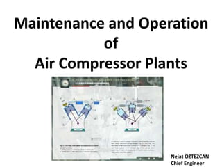
- 16. 3 2 1 4
- 17. The Compressed Air system is designed to generate and supply compressed air for ship systems by: 1.Compressed Starting & Service Air System. 2.Control Air System. Starting Air System The Starting Air System produces and supplies compressed air for starting ME and DEs. All engines are started by means of compressed air with a nominal pressure of 3 MPa (30 bar). In automatic operating mode, the Main Start Air Compressors are switched on by the pressure control at low pressure 28 bar (LEAD)and 26 bar (FOLLOW), respectively switched off at max pressure 30 bar (FOLLOW) and 30 bar (LEAD). The compressors can be also operated manually from the LOP.
- 18. Control Air & Service Air System The Control Air & Service Air System produces and supplies compressed air for pneumatic mechanisms (e.g. valves, pumps) and safety and control devices. In automatic operating mode, when the pressure in the Air receiver drops <7.5 bar the compressor automatically starts. The compressor can be also operated manually from the push button box.
- 20. Bumping clearance in an air compressor This is a clearance must be provided between the piston top and the cylinder head when the piston is top dead centre. It must be kept as small as possible for achieving the best compressor efficiency. Why need bumping clearance in an air compressor ? •To prevent mechanical damage to the compressor. •To provide for thermal expansion •To provide necessary space for valve operation. How to adjust the bumping clearance ? It can be adjusted by two ways. •By altering the head gaskets (cover joint ) thickness. •By adding and subtracting shims between the connecting rod foot and bottom and bearing.
- 21. Main air compressor bumping clearance taking procedure •Stop the compressor and (lock off) take out fuse. •Drain the cooling water. •Remove the cylinder cover. •Clean the cylinder head face and piston crown. •Place the lead wire ball on the top face of the piston. That is larger size than expected by clearance. •Cylinder cover is placed on the cylinder with correct joint thickness and tightens the head bolts. •Turn the compressor slowly by hand over top centre so that lead wire ball is pressed. •Then remove cylinder cover again. •Remove the compressed lead wire ball. •Take the measurement of lead wire thickness by using micrometer.
- 22. Air Receivers
- 25. Control Air Dryer (Refrigerant-type)
- 27. Compressors are classified in many ways out of which the common one is the classification based on the principle of operation. Types of Compressors: 1. Positive Displacement and 2. Dynamic Compressors. Positive displacement compressors can be further divided into; Reciprocating and rotary compressors. Under the classification of reciprocating compressors, we have •In-line compressors, •“V"-shaped compressors, •Tandem Piston compressors. •Single-acting compressors, •Double-acting compressors, •Diaphragm compressors.
- 28. Reciprocating compressor: It is a piston-liner assembly, piston is attached to the crankshaft via a connecting-rod. The shaft is further coupled to motor which drives the assembly. It is used onboard to fill compressed air into air bottles mainly to supply starting air to main and auxiliary engine, and for other subsidiary purposes.
- 29. Reciprocating In-line Compressors: These are most commonly used compressors with varying pressure ranges. These are simple in design with almost very little automation. The cylinders of various stages are found in a straight line when seen from top. These compressors are commonly direct driven by electric motors or diesel engines. Refer the attached diagram of the reciprocating in-line compressors.
- 30. Single acting compressors They are the reciprocating compressor which has piston working only in one direction.The other end of the piston is often free or open from which no work is performed.There is only one side compression or the upper part of the piston is used to compress the air.the bottom part is open to crankcase and is not utilized for the compression of air.
- 31. Double acting compressors As from its name it uses its both sides to compress the air. These type of compressors have two sets of suction/intake and delivery/exhaust valve on both sides of the piston. As the piston moves up and down,both sides of the piston is utilized in compressing the air.The intake and exhaust valve operates corresponding to the movement of the piston or with the stroke of the compressor. The air is compressed accordingly and delivered continuously as compared to single-acting air compressor
- 32. Single Stage, Double Acting Reciprocating Compressors
- 33. V-shaped compressors They are come under air cooled compressors with concentric valves mounted on each cylinder head unit which are placed in V- shaped i.e. at the angle of 90 degrees from each other and may or may not be connected to same crank pin on the crank shaft. They are compressors of higher capacity so the cooling is required.The v-shaped is given to such compressor for achieving better torque and balancing by displacing different units at some angle.
- 34. The rotary compressors are divided into •Screw compressors, •Vane type compressors, •Lobe and scroll compressors and other types. Under the Roto-dynamic compressors, we have •Centrifugal compressors, and the •Axial flow compressors.
- 35. Vane Type Rotary Compressor This is an another type of rotary compressor. There is a fixed casing in Vane type compressor in which a rotary rotor disc is placed which has slots that are used for holding the sliding plates. Whenever rotor rotates the disc also rotates thus allowing the sliding plates to slide as the inner surface of casing is eccentric. Whenever the plates moves away from the center a huge amount of air get trapped inside it and with the rotation the sliding plates converge due to its shape and the trapped air get compressed.This results in compression of air.
- 37. Lobe Type Air Compressor This is one of the simpler compressor type.In this there is no complicated moving part.There are two lobes attached to the driving shaft by the prime mover.These lobes are displaced with 90 degrees to one another.Thus if one of the lobe is in horizontal direction the other lobes will be exactly positioned at 90 degree i.e in vertical direction. The air gets trapped from one end and as the lobes rotates the air gets compressed as shown in image. The compressed air is then delivered to delivery line.
- 38. Dynamic Compressors. Dynamic compressors operate by imparting velocity and pressure to the admitted air, through the action of a rapidly spinning impeller or rotating vanes. The main types of dynamic compressors are centrifugal (radial) and axial compressors.
- 39. Centrifugal compressor: It consists of a rotary wheel with blades mounted on them, the wheel and blades when rotated develops a negative pressure, the inducer guides air into the blades . Centrifugal force generated due to moving blades increases the velocity of air. The air is guided to the diffuser which acts as a divergent nozzle and reduces the velocity and increases the pressure. Thus, the density of air i.e mass per unit volume increases. It is used onboard in turbocharger , for supplying compressed air for combustion in engine cylinder.
- 40. Axial Flow compressor • It consists of a casing fitted with several rows of fixed blades and rotor attached with several rows of moving blades. • The fixed and moving blades are placed on alternate rows the function of the fixed blades is to receive the high velocity air from the moving blades. • Axial flow compressor is also a high speed machine and speed may even vary from 10,000 to 30,000 RPM. Pressure ratio of 10:1 can be achieved.
- 41. A Centrifugal compressor primarily consists of; 1.Stationary casing 2.Rotating Impeller 3.Diffuser Centrifugal compressor is also known as Radial Compressor.
- 42. The compressors are also classified based on other aspects like •Number of stages (single-stage, 2-stage and multi-stage), •Cooling method and medium (Air cooled, water cooled and oil- cooled), •Drive types ( Engine driven, Motor driven, Turbine driven, Belt, chain, gear or direct coupling drives), •Lubrication method (Splash lubricated or forced lubrication or oil-free compressors). •Service Pressure (Low, Medium, High)
- 45. İki kademeli ara soğutmalı Kompresör
- 48. Why multistage compressors are mostly used than single stage compressor ? •More stages are needed to increase the required final pressure. •Easier to control the air temperature. •Reducing in air compressor size. •Lubrication problem does not exit. •Reduced the thermal stress. •Lower work done to compressing air. •Improve compressor efficiency
- 49. What is multi-staging in compressor and why is it done? Multi-staging is conducting the process of compression in more than one stagesi. Air is compressed by two or more pistons before delivery. Generally, two stage reciprocating compressors are used on board. The purpose of multi-statging is : 1. If we increase the pressure of air up to 30 bar (pressure of air at 2nd stage) in one stage, the Lub.oil will start burning due to rise in temperature. As per the thermodynamic equation for a polytropic process, T2 / T1 = ( p2 / p1 ) (n-1)/n where n=1.35 for air. p2/p1= 30/1 T1=27 deg-celcius. T2= 450 deg-celcius. at this temperature l.o will burn as flash point of Lub.Oil is 200 deg. celcius. So we keep the pressure ratio limited to 5:1.
- 50. 2. To reduce the work done by compressor in the whole process. The compression of air to higher pressure and lesser volume is a reversible adiabatic process. Change in temperature takes place, if change in temperature is kept minimum or zero , the work done by compressor will be minimum.
- 51. What are the normal parameters of air compressor ? •LP discharge pressure: 4/5 bars •HP discharge pressure: 30 bars. •Intercooler inlet air temperature: 130 ° C •Intercooler outlet air temperature: 35 ° C •After cooler inlet air temperature: 130 ° C After cooler outlet air temperature: 35 ° C Why need minimum lubrication for air compressors ? •To prevent carbonizing of the valves •To avoid loss of compressor efficiency due to sluggish action of valve •To avoid loss of cooler efficiency due to deposition of oil on the cooling surface •To prevent air line explosion, to prevent air bottle corrosion
- 52. AUXILIARY EQUIPMENT Air Intake Filters: Filters prevent the admission of atmospheric dust to the air compressor. Silencers: Silencers reduce objectionable compressor suction noise. Separators: Separators remove and collect entrained water and oil precipitated from the air. Traps: Traps drain condensed moisture and oil from separators, intercoolers, aftercoolers, receivers, and distribution piping. Air Receivers: Air receivers are tanks wherein compressed air is discharged and stored. They help to reduce pulsations in the discharge line and provide storage capacity to meet peak demands exceeding the capacity of the compressor.
- 53. INTAKE FILTERS Air filters are provided on air compressor intakes to prevent atmospheric dust from entering the compressor and causing scoring and excessive wear. There are two types of air filters, the dry type and the oil-wetted type. Dry type filters must be cleaned and replaced more often than oil- wetted types. Oil-wetted types are often used where there are heavy dust concentrations present in the atmosphere.
- 54. 54Wet Filter Air Intake System ToEngine
- 55. SEPARATORS Separators are used on compressor installations to remove entrained water and oil from the compressed air. Centrifugal action forces the moisture particles against the wall of the separator where they drain to the bottom. In the baffle type separator the air is subjected to a series of sudden changes in direction. The heavier moisture particles strike the baffles and walls of the separator and drain to the bottom of the unit.
- 57. TRAPS Traps drain condensed moisture from intercoolers, aftercoolers, receivers, and distribution piping. The most common traps are the ball float trap, bucket trap, and inverted bucket trap. Daily Inspection: Check the operation of drain traps daily. Make sure the trap is draining properly and not blowing air.
- 58. AIR RECEIVERS Air receivers serve as reservoirs for the storage of compressed air so that air is available to meet peak demands in excess of the compressor capacity. They also function as pulsation dampers on reciprocating compressor installations. Receivers are furnished with a relief valve, pressure gauge,drain valve, and inspection openings. NORMAL OPERATION: Drain receivers of accumulated condensate at least once each shift if an automatic drainer is not provided. Periodic Inspection: Proceed as follows at intervals prescribed by the manufacturer's maintenance schedule. (a) Check operation of safety valve. (b) Examine receiver for corrosion and peeling paint. (c) Inspect the receiver internally for corrosion and dirt accumulation.
- 59. Safety devices on main air bottle ? •Safety valve. •Fusible plug.(if safety valve is not directly fitted on the bottle) •Pressure gauge. •Low air pressure alarm. •High air pressure alarm •. •Moisture drains valve.
- 60. DRYERS Compressed air dryers remove moisture that might otherwise condense in air lines, air tools, and pneumatic instruments. This condensate can cause damage to equipment from corrosion, freezing, and water hammer, and can cause malfunctioning of instruments and controls. Air dryers remove moisture that might condense in air lines, air tools, or pneumatic instruments
- 61. What Is a Compressed Air Dryer? A compressed air dryer is a machine that sucks in and significantly reduces the moisture content of ambient air. Depending on the moisture levels of a given environment, the use of a compressed air system can make all the difference between whether or not a production is even achievable. Compressed air dryers can be split into the following categories: •Refrigerated drying units: •Desiccant drying units: •Heated — internal or external The main difference between each dryer type is the agent placed inside the machine to dry the incoming air.
- 62. . Intercoolers and Aftercoolers: Intercoolers are used between consecutive stages of multistage compressors to remove the heat of compression. Aftercoolers are installed on the compressor discharge lines to remove the heat of compression after compression is completed. Both are effective in removing moisture and oil from the compressed air.
- 63. There are two types of heat exchangers used on air compressors. •Air-Cooled Heat Exchanger: Air-cooled heat exchangers are most often used on small compressors. The air-cooled heat exchanger is a finned, tubular radiator. •Water-Cooled Heat Exchanger: The most common design of water- cooled heat exchangers, shell and tube type, consists of a single bundle of tubes enclosed inside a cylindrical shell . The air to be cooled passes through the tubes while the water passes over the tubes. Baffles are often provided in the tube bundle to direct the waterflow across the heat exchanger tubes in the most efficient manner.
- 64. The intercooler is located between the discharge of one cylinder and the intake of the next cylinder of multistage compressors. The intercooler reduces the temperature and the volume of the compressed air for delivery to the next compression stage. The aftercooler is located at the discharge of the last cylinder to cool the air, reduce its volume, and to liquify any condensable vapors.
- 65. Advantages of after cooler in air compressor ? •To reduce final discharge air temperature thus air bottle size can be reduced. •To reduce air volume after it has been compressed to the final pressure. •So greater amount of air could be stored in air bottle. •Increase volumetric efficiency
- 66. Section view of a water cooled intercooler
- 67. Why Intercooler is fitted in air compressors? •Reduce air temperature and volume, and increase air density for next stage. •Increase Compressor Capacity and Volumetric Efficiency. •Better lubrication for cylinder and rings. •Water and excess oil can be drained out, preventing fouling of Intercooler and pipes, Air Bottle corrosion, and starting airline explosion. •Metal stresses reduced, due to control of temperature.
- 68. Different Parts of a Marine Air Compressor Used on a Ship 1) Cylinder liner: It is made of graded cast iron and is accompanied with water jacket around it to absorb heat produced during compression process. It is designed so as to give a streamline passage to the pressurized air resulting in minimum pressure drop. 2) Piston: For a non-lubricating type compressor, light weight aluminum alloy piston are used and for lubricating type graded, cast iron piston are used with piston rings for sealing and scrapping off excess oil. 3) Piston Rod: In high capacity compressor which is normally big in size, piston is attached to piston rod made up of alloy steel. They are fitted with anti friction packing ring to avoid chances of compressed air leakage.
- 70. 4) Connecting rod: Connecting rod plays its role to minimize thrust to the bearing surface. It is made up of forged alloy steel. 5) Big end bearing and Main bearing: They are constructed to give rigidity to the running rotational mechanism. They are made up of copper lead alloy and have a long operational life if proper lube oil and lubrication is provided. 6) Crank shaft: It is a one piece designed part, using counterweights for dynamic balancing during high speed of rotation to avoid twisting due to torsion forces. Connecting rod big end bearing and main bearing are connected to crank shaft at crank pin and journal pin which are polished to ensure long working life of bearings.
- 71. 7) Frame and crankcase: Normally they have rectangular shape and accommodate all the moving parts and that’s why are made up of rigid cast iron. Main bearing housing is fitted on a bore in crank case and is made with highest precision to avoid eccentricity or misalignment. 8 ) Oil pump: A lubricating oil pump is fitted to supply lube oil to all the bearings, which can be chain or gear driven, through crank shaft. Pressure of oil can be regulated by means of regulating screw provided in the pump. A filter in the inlet of the pump is also attached to supply clean and particle free oil to the bearings. 9) Water pump: Some compressor may have attached water cooling pump driven by crankshaft through chain or gear. Some system does not use attached pump as they use water supply from main or auxiliary system for cooling.
- 72. 10) Suction and Discharge valve: These are multi-plate valves made up of stainless steel and are used to suck and to discharge air from one stage to another and to the air bottle. Proper assembling of valves is very important for efficient operation of the compressor. 11) Inter-coolers: Inter-coolers are normally fitted in between two stages to cool down the air temperature and to increase the volumetric efficiency of compressor. Some compressor have inbuilt attached copper tubes for cooling and some have outside assembly of copper tube inter-coolers. 12) Driving Motor: An Electrical motor is attached to the compressor for making it operational and is connected to the compressor through the flywheel.
- 73. 1. Compressor Housing • Main cross head, connecting rod and motor bearings 2. Cylinder Area • Valves, packing and compression rings There are 2 areas that require lubrication in a reciprocating compressor. Lubrication
- 74. Splash Lubrication • Most common in small compressors. Pressurized Lubrication • Usually used on very large compressors. There are 2 different methods of lubrication. • Use “dippers” on the connecting rod to scoop oil out of the crankcase. • A gear pump is used to force oil through orifices in the connecting rods.
- 75. What is the type of cylinder liner lubrication in compressor and how is it done? For 2 stage compressors, which has two different in-line cylinder arrangement for both stages, splash lubrication of liner and piston takes place. The l.o from sump is splashed by the movement of the shaft into the liner walls and is scraped back by the oil scraper ring. For two stage tandem type (in which only one cylinder liner is used and both pistons are connected), for 1st stage lubrication a separate line is connected to the suction side , as air is drawn in for compression, an oil mist of l.o and air is also carried to the 1st stage. Thus, a l.o film is generated and boundary lubrication takes place. 2nd stage lubrication takes place by splash of l.o by the crankshaft and is scraped down by the oil scraper ring.
- 76. What are the safety devices on Main Air Compressor: •Bursting Disc on Intercooler: (At water side) •Bursting Disc and Fusible Plug (105°C) on Aftercooler •Relief valves on LP and HP stages. (Set to lift at 10% rise above normal stage pressure.) •Automatic Moisture Drain Valve. •Cooling water supply failure alarm. •Low LO pressure alarm. •Relief valve on crankcase LO pump. •Delivery air HT cut out and alarm on Aftercooler outlet. (Max. 93°C) LP discharge pressure 4 bars and HP discharge pressure 30 bar Intercooler inlet air 130°C and intercooler outlet air 35°C Aftercooler inlet air 130°C and Aftercooler outlet air 35°C:
- 77. Safety Valves: Safety valves are used in a compressed air or gas system. They must open rapidly and fully so that excessive pressure buildup can be relieved immediately to prevent damage or destruction of the system components. Although the terms safety valve and relief valve are often used interchangeably, this is technically incorrect. A relief valve is used with liquid systems. Safety valves are found in interstages air receivers, and between a positive displacement compressor and any shutoff valve.
- 78. Difference between relief valve, bursting disc and fusible plug ? Pressure relief valve •Excess pressure is released by opening the valve. •It opens at 10% over working pressure. •Valve lift is proportional to excess pressure build up. •Valve setting pressure can be altered by spring tension. Bursting disc •Pressure is released by bursting the disc. •It permanently damaged. •It burst at setting pressure. •Setting pressure cannot be altered in place. Fusible plug •When the air temperature from compressor is high (above 105 ° C) pressure is released by melting (fusing) the metal. •It cannot be used next time. ( permanent damage) •Release all content or pressure to empty.
- 79. Bursting Disc: Fitted on the shell of Intercooler at waterside. Relieves pressure if the tubes burst. Bursting disc is fitted for totally release and stop operation circuit. Release valve opens excess pressure at compressor running and reset when pressure reduce or when the compressor is stopped. Thus cooling water can enter to compressed air space; it can cause water hammer when the next start of compressor.
- 81. Where is the fusible plug fitted and its purpose ? Fusible plug is fitted under side of the pipe between relief valve and air bottle. It is fitted to release the compressed air in the event of abnormally high compressed air temperature. Fusible plug melt at 105 °C and release all content of air. It is made by 50% bismut, 30% tin, 20% lead. A fusible plug is fitted after the second stage cooler to limit the delivered air temperature and thus protect the compressed air reservoirs and pipe work. Fusible plug is fitted at main air bottle, when relief valve is fitted indirectly to the air bottle.
- 82. Compound Valves, why used in Air Compressor? • Give large area of opening and small amount of valve lift. • Improve Volumetric Efficiency, as valve open and close in minimum time. • Reduce bumping clearance. • Reduce wear and tear.
- 83. Leaky Valves in Air Compressors Valves can leak and finally fail. Valves may fail owing to wear and fatigue, insufficient of over-lubrication, presence of foreign particles, oil decomposition and excess valve lift.
- 85. Intake and Discharge Valves • Work very similar to check valves • Can open and close 720,000 time a day • The number 1 reason for compressor downtime is valve failure • Check the temperature of the valves regularly
- 86. TYPE OF THE VALVE PLATE METALS •Staınless steel •Carbon steel •Cast ıron ASPECTS TO THINK ABOUT PRIOR TO CHOOSING VALVE PLATE METALS Run-time: The amount of time that the compressor will be running makes a huge impact on which metal would be the right choice. Environment: Corrosion is the natural enemy of metal. It occurs through oxidation, most from the presence of both oxygen and water. Vibrations: If there is more vibration than what would be considered normal running conditions, then you should take this in to account . Heat: If your compressor just generates more heat than what would be considered normal running conditions, you need to choose a metal that will handle the extra temperature. Pressure: If the compressor you are putting the valve plate is large, then you will need to make sure the metal will withstand any pressure that the compressor might generate.
- 87. CONTROLS: Control systems for air compressors vary from the relatively simple to the extremely sophisticated. The simpler control systems, through the use of sensors, monitor the performance of the equipment and, through the use of lights and/or audible signals, alert an operator that some variable is outside the normal operating range. Most systems automatically initiate a shutdown procedure under certain conditions to prevent equipment damage. COOLING WATER TREATMENT: Cooling water systems are used in compressed air plants to remove heat from engines, air compressors, refrigeration condensers, intercoolers, and aftercoolers. These cooling systems are classified as either once-through or recirculating. Treatment is more critical in open recirculating systems because of solids buildup due to evaporation.
- 88. What is a discharge unloader and describe its operaton? One of the most important component, an unloader is used for unloaded starting of compressor and draining at continuous intervals. An unloader is fitted at the end of drain line from inter and aftercooler. It is basically a solenoid operated spring loaded valve arrangement. When compressor is shut and delivery air pressure is zero, the drain opens the unloader valve against spring pressure, thus it is always open. When started, slowly the delivery pressure rises and tries to shut the valve, during this time the actuated solenoid valve overcomes the air pressure and keeps the valve open.
- 89. The solenoid valve is operated by a time delay circuit as the time span of 10-15 sec gets over the solenoid is deactivated and the unloader valve shuts. After every 20-30 mins.It is activated again and clears the drain for 10-15 secs, then deactivates. If the unloader does'nt function properly, there is a manually operated valve just before unloader, which should be open before starting the unloader. Why is it so important to start the compressor in unloaded condition? It must be unloaded because when started the compressor draws a very high current, if it will be loaded and valve not open. The motor which is driving the machine may get overloaded.
- 90. Inlet Valve Unloader: There are several methods of unloading the compressor. One system holds the inlet valves open mechanically during both the suction and compression strokes, thereby preventing the air from being compressed. The unloader is located above the inlet valve so that the yoke fingers are almost touching the valve. When the air receiver pressure rises to the preset unloading pressure, a pressure switch operates a solenoid unloader valve which operates and sends air receiver pressure to the inlet valve unloader. The pressure from the air receiver acting on the diaphragm of the inlet valve unloader forces the yoke fingers against the inlet valve, holding it open. The intake air is pushed back out of the inlet valve on the compression stroke so that no compression takes place.
- 93. Pressure reducing valves If it is necessary to provide steam or air at a pressure less than that of the boiler or compressed air reservoir, a reducing valve is fitted. This will maintain the downstream pressure within defined limits over a range of flow, despite any changes in supply pressure. There are systems onboard a ship which are operated by pneumatics or hydraulics and sometimes even air or electronics. For this reason, the relief valve by construction and operation should be such that even in case of failure of the control system, relief valve must lift to safeguard the system from over pressurized.
- 97. OPERATION AND MAINTENANCE RESPONSIBILITIES OPERATION: Operation includes startup, normal operation, emergency operation, and shutdown of plant equipment. Good operation is safe, reliable, and economical. Follow these basic rules of good operation. • All operators should be thoroughly familiar with the equipment and systems they operate. Carefully study drawings, diagrams, instruction manuals, special operation procedures, and emergency procedures. • Perform work assignments in a safe manner in accordance with approved operating procedures. Use available protective safety clothing and equipment. • Operate equipment and systems economically, safely, and reliably. • Teamwork and cooperation are essential. • Be alert and concentrate on your work. Errors and forgetfulness can cause serious personnel injuries and costly damage to equipment.
- 98. How to start the air compressor manually on ships ? •Change the switch to manual position on the switch board. •Check the L.O sump level and condition. •Open the moisture drain valve. •Open the compressor discharge valve & charging valve of air bottle. •Open cooling water system valves. •Turn the compressor flywheel by hand (one turn). •Start the motor, after draining the moisture shut the drain valve. •Check the motor ampere consumed. •Check the pressure gauge readings. •Frequently drain the moisture. •When charging full, open drain valve and stop the compressor
- 99. What is first start arrangement on ships ? •Firstly start the emergency air compressor to fill up the air to the emergency air bottle up to desired pressure obtained. •Drain out oil and water. •Open emergency air bottle outlet valve and pressed up desired pressure. •Then start the generator with correct procedure. •Close the breaker and switch on the lighting. •Start the required machinery ( especially G/E FO booster pump, SW cooling pump, E/ R blower). •Start the main air compressor and press up to main air bottle. •After that, M/E warming by using generator jacket water and start the L.O pump.
- 100. Air Compressor Problems 1. Compressor Capacity is Low: This is one of the most common problems seen on all types of ships. Often, compressor capacity can go low or reduced if it is running for long time and eventually it is unable to cope up with the air demand. Main reasons for this problem are: •Leakage in discharge and suction valves •Fault or leakage in the unloader •Leakage from relief valve •Increase in bumping clearance •Wrong setting of compressor auto cut-in and cut-out (too close)
- 101. 2. Oil Carry Over in Air: If the compressed air in the system is carrying oil, would be mainly because of the following reasons : •Oil separator is not working correctly hence oil is being carried to the air receiver •The cylinder lubrication is adjusted at high quantity, leading to carry over of oil with air •The auto drain is malfunctioning
- 102. 3. Excessive Vibration and Noise: If the compressor is generating too much of noise and vibration, it can be because of the following reasons: •Loose pulley, flywheel, belt, belt guard, cooler, clamps or accessories •Lack of oil in the crankcase •Piston hitting the valve plate i.e reduced bumping clearance •Compressor holding down bolts are loose •Compressor foundation chocks worn out
- 103. 4. Overheating of Discharged Air If the temperature of the discharged compressed air is high, it can be because of overheating caused as a result of the following reasons: •Chocked or dirty intercooler tube •Cooling water pump capacity decreased or insufficient •The atmosphere at air suction of compressor is hot •No forced ventilation for fresh air near compressor •Damage in the head gasket •Chocked air suction filter •Valves of 1st or 2nd stage leaking
- 104. 5.Milky Oil in the Crankcase If there is a accumulation of milky colored oil in the crankcase, it can be because of the following reasons: •Water leakage from cylinder liner •Water leakage form jacket •Oil running hour is over
- 105. 6. Lube Oil Pressure Low The following can be the reasons for lube oil pressure low in Air Comp. •Faulty pressure gauge or Cock to pressure gauge in closed position. •Low oil level in the sump. •Leakage in supply pipe. •Suction filter is choked. •Oil grade in the crank case is not compatible. •Attached Lube oil gear pump is faulty. •Worn out Bearing, clearance is more.
- 106. Cooling water temperature is high Cooling water temperature can go high because of the following reasons: •Inlet or outlet valve for cooling water is closed. •Inter-cooler is chocked. •Cooling water in the expansion tank is low. •Pipe passage becomes narrow due to scale formation. •Water-pump belt or gear drive broken. •Pump not working.
- 107. First stage discharge pressure high In case the first stage discharge pressure is high, it must be because of : •Pressure gauge is faulty. •Inter-cooler air passage is chocked. •Second stage suction valve is not closing properly, allowing air to escape from 2nd to 1st stage. •Discharge valve of first stage is malfunctioning, and remains in closed position. •Spring of discharge valve is malfunctioning.
- 108. First stage discharge pressure low In case the first stage discharge pressure is low, it must be because of : •Pressure gauge is faulty. •Suction filter is choked. •Unloader of first stage is leaking. •First stage suction valve is not closing properly, resulting in compressed air leakage. •First stage suction valve is not opening fully, leading to less intake of air. •Discharge valve is faulty and remains open permanently. •Relief valve after first stage is leaking. •Piston ring of first stage is badly worn out, allowing air to pass.
- 109. Second stage discharge pressure high: In case of high discharge pressure in the second stage, the reasons can be: •Faulty pressure gauge. •Discharge valve to air bottle is shut. •Second stage discharge valve plate worn out, and even the spring worn out. •Valve is stuck in closed position. •After cooler air passage choked. •Air bottle is over pressurized.
- 110. Second stage discharge pressure low: When second stage discharge pressure is low, it could be because of: •Pressure gauge is faulty. •Suction valve for second stage is malfunctioning, in open position. •Suction valve for second stage is not opening fully, and thus less intake of air. •Discharge valve is faulty and remains open during operation. •Piston rings of second stage are worn out, leaking out compressed air. •Relief valve of second stage is leaking. •Un-loader of second stage is leaking.
- 111. What are the safeties in a reciprocating compressor? 1. Lubricating oil pressure low cut out: It is provided such that if lub. oil pressure falls down the parts which are lubricated like liner, piston, main bearings, bottom end bearings might get worn out. 2. Bursting disc: It is given in intercooler and aftercooler in the water side so that if any highly pressurized air tube bursts, the cooler shell will not be pressurized, bursting disc will burst and liberate all the water, indicating air-tube burst. Generally made of copper. 3. Non- return valve in delivery line: It is provided, so that the air once delivered does'nt return back to the compressor in case a low pressure develops in compressor side. 4. Discharge unloader:
- 112. 5. Relief valve on intercooler: A relief valve with setting 10% above the 1st stage pressure is provided to release air if high pressure is generated ın 1st stage generally due to valve malfunction. 6. Fusible plug: Generally made of tin, antimony and bismuth, is fitted in inter and aftercooler to release excess air when temperature rises up to 121 degree celcius due to rise in pressure. 7. High temperature alarm: At around 90 degree celcius, the alarm sounds denoting the rise in air temperature.
- 113. SAFETY PRECAUTIONS Explosive Hazards. Although compressed air at low or medium pressures is dangerous if carelessly handled, the dangers associated with high-pressure systems are of much greater consequence. Serious explosions, complete destruction of facilities, and heavy loss of life have been attributed to unsafe practices involving high-pressure compressed air systems. The air temperature in the confined space is raised to the ignition point of any flammable material that may be present. Preventive Measures: 1. Use of Slow-Opening Valves. These valves are used in pocketed spaces such as lines to gauges and regulators to prevent a sudden pressure rise.
- 114. 2. Pipe Coloring: High-pressure air lines are identified with a painted light gray band and adjoining light green arrowhead pointing in the normal flow direction. 3. Location of Equipment: High-pressure air storage and dryer cylinders are isolated from other facilities as a precaution against damage that could result from rupture of the cylinders. 4. System Tests: Before putting a high-pressure system into operation, the required testing must be accomplished by competent personnel with an engineer responsible for safety.
- 115. STARTUP Prestart Inspection: Carefully inspect the compressor installation to ensure the following prestart requirements are fulfilled. (a) Verify all installation and repair work has been completed. (b) Ensure system has been cleaned and tested for leaks. (c) Ensure interstage and discharge safety valves are operating properly. (d) Ensure compressor and drive are lubricated in accordance with the manufacturers' instructions. On units fitted with a forced mechanical lubricator, pump or crank by hand to see that the oil is getting to all parts requiring lubrication.
- 116. Startup Procedure for Motor-Driven Compressors. Proceed as follows: (a) Open all shutoff valves between compressor and receiver. (b) Make sure compressor is unloaded. Consult the manufacturer's instructions for procedure. (c) Turn on cooling water, if provided. Thoroughly vent cylinder jackets and coolers if vents are provided. (d) Turn compressor over by hand to see that all parts are free. (e) Start compressor motor. When up to speed, apply load if machine is running smoothly.
- 117. Startup Procedure for New or Overhauled Compressors: When starting a new compressor, or one that has been overhauled, allow the compressor to run unloaded for 1 or 2 hours to give the running surfaces a polished finish. Periodically check for overheating. Build up load gradually over a period of several hours. After a few days of operation, shut down compressor and recheck all cylinder head, valve cover, cylinder flange, shaft cover, and foundation bolts for tightness.
- 118. NORMAL OPERATION: While the system is operating, perform the following tasks. (a) Watch for irregular compressor performance; excessive vibration; and overheating of bearings, motors, and packing. (b) Maintain proper lubricating oil levels. (c) Drain intercooler and aftercooler separators as necessary. (d) If automatic drainers are provided, check their operation. (e) Check temperatures and pressures of cooling water, compressed air, and lubricating oil regularly.
- 119. SHUTDOWN: Proceed as follows: (a) Unload the compressor before stopping the drive. (b) Drain separators, steam cylinders, and turbines. (c) Shut off cooling water supply if an automatic shutoff valve is not provided. (d) If the compressor might be subjected to freezing temperatures while shutdown, thoroughly drain cylinder jackets, coolers, and drain traps.
- 120. Extended Shutdown. Any compressor taken out of service for an extended period will deteriorate rapidly from rust and corrosion if not properly protected. (a) Drain and refill the crankcase with a preservative oil. (b) Operate the machine without pressure for no less than 15 minutes. This allows thorough distribution of the oil and elimination of any crankcase condensate. (c) While the machine is running, spray a fog of preservative oil into the compressor intake. (d) Remove piston rod packing and oil wiper rings from the rod or corrosion of the piston rod may result. Coat the piston rod and oil wiper rings with grease and wrap them in waterproof paper. (e) Tape or plug all openings to keep out moisture. (f) Relieve V-belts of tension. (g) Drain the receiver and aftercooler. (h) Drain the aftercooler cooling water, if used.
- 121. Good Practices for Safe and Efficient Operation of Air Compressors on Ships •Check oil level in sump. Do not overfill. Excessive oil consumption or pressure build up in the crankcase to be observed, investigated and rectified as soon as possible. •Drain all air bottles regularly. •Ensure air to deck, service air is shut when not in use. •Give attention to any air leakages reported and rectify. •Daily record running hours and log it. •Daily check automatic drains and unloader of air compressor for proper functioning.
- 122. •Weekly check the operation of the relief valves connected to the LP, HP stages by operating manually. •Follow planned maintenance as per manufacturer’s manual. •Air filter to be renewed every 500 hours. •Compressor valves to be removed for inspection every 1000 hours. •Do not reverse valve plates. There is a danger of fatigue cracking. •Every automatic drain valves to be stripped, cleaned and checked ev. 2000h. •Every relief valves to be stripped, cleaned and overhauled, set at correct press. •Major overhaul to be carried out as per PMS.
- 123. OPERATIONAL PREVENTIVE MAINTENANCE: Operational preventive maintenance includes the following tasks. (a) Keep daily operating logs that record pressures and temperatures of air and water in the compressor, intercoolers and aftercoolers, and of compressor lubricating oil. Deviations from normal values indicate the corrective action that must be taken to return the system to normal and to prevent damage to the equipment from insufficient lubrication or inadequate cooling. The operating log also helps in detecting valve troubles. Locate defective valve by feeling the valve cover plates and determining which is the hottest.
- 124. (b) Keep compressor clean at all times. Wipe the machine daily with a cloth. Dirt on the machine will eventually work its way into the lubricating system. (c) Clean intake air filter regularly to prevent atmospheric dust from entering the compressor cylinders. (d) Keep piston rod packing tight enough to prevent air leakage, but do not overtighten. Overtightening causes excessive packing wear and scoring of the piston rod.
- 125. Quarterly Inspection: Inspect the compressor every 3 months for the following conditions: (a) Wear and dirt on, and proper seating of, compressor valves (b) Operation of all safety valves (c) Wear of packing and scoring of piston rods (d) Sludge accumulations in crankcase (e) Tightness of cylinder head bolts (f) Tension, wear, and deterioration of belts (g) Wear of connecting rods and crossheads (h) Wear of, and dirt in, bearings (i) Operation of lubricators and oil cups
- 126. Annual Inspection. Repeat the quarterly inspection outlined above and inspect for the following conditions: (a) Wear, scoring, and corrosion of, and dirt in cylinders (b) Leakage, wear, scoring, and security to the piston rod of pistons; (c) Damage, wear, and tightness of, and dirt in, piston rings (d) Wear at packing glands of piston rods and security of piston rods to crosshead and piston, check head clearances (e) Wear and proper operation of crankcase and crankshaft bearings (f) Wear and proper operation of crossheads, crosshead guides,and pins (g) Security to shaft of flywheel; wear and dirt on flywheel bearings (h) Alignment of compressor with drive
- 127. MAINTENANCE: Lubrication: Establish a lubrication schedule for air compressors. Normal oil levels must be maintained at all times. Use only lubricants recommended by the manufacturer. Frequency of oil changes is dependent upon severity of service and atmospheric dust and dirt. The time for oil changes can best be determined by the physical condition of the oil. When changing oil, clean the inside of the crankcase by wiping with clean, lint-free rags. If this is not possible, use a good grade of flushing oil to remove any settled particles.
- 128. Cleaning: Cylinder jackets of water-cooled compressors should be cleaned annually with water. Dirt accumulations interfere with water circulation. Cleaning can be accomplished using a small hose nozzle to play water into the jackets. On compressors fitted with mechanical lubricators , cylinders may be cleaned with a nonflammable cleaning fluid. Do not use gasoline,kerosene, or other low flashpoint solvents. A serious explosion may result.
- 129. Valves: Replace all defective valve parts as required. When a valve disk or plate wears to less than one-half its original thickness, it should be replaced. Valve seats may be resurfaced by lapping or regrinding. On some valve designs it is necessary to check the lift after resurfacing. Carbon deposits should be removed and the valve assembly washed in nonflammable cleaning fluid. Before replacing valves, make sure the valve seat and cover plate gaskets are in good condition. If any defects are found, replace the gaskets. Make sure the valve is returned to the same port from which it was removed.
- 130. Piston Rings: When replacing worn piston rings, the new rings must be tried in the cylinder for fit. If the cylinder wall is badly scored or out of round, rebore the cylinder, or if cylinder liners are fitted, replace them. If necessary to file for end clearance, take care to file the ends parallel. Clean the ring grooves and remove any carbon deposits before installing the new rings. To install new rings, place several metal strips not more than 0.032-inch ( 0,8 mm) thick between the piston and rings. Make sure the ring is free by rotating it in its groove.
- 131. Piston End Clearance: (Bumping Clearance) Always check piston end clearance after replacing pistons or after adjustment or replacement of main, crankpin, wristpin, or crosshead bearings. To measure piston end clearance, insert a solder into the cylinder through a valve port and turn the compressor over by hand so that the piston moves to the end of its stroke.
- 132. Bearings: Sleeve type main bearings are adjusted by removing or adding metal shims between the cap and body of the bearing housing. The same number of shims should be added or removed from each side of the bearing. Make sure caps are tightly secured so they cannot work loose. Do not overtighten as this causes overheating of the bearing.
- 133. V-Belt Drives: Adjust tension or replace V-belts as required. When one or more belts in a set require replacement, replace the entire set with matched belts. If this is not done, the new unstretched belts, being shorter than the old belts, will carry most of the load and will be subjected to undue strain. Removed belts that appear to be in a serviceable condition may be kept for emergency use.
- 135. General Problems of Air Compressors on Ships Most of the problems associated with air compressors lead to increase in running hours. They are: •Leaking automatic drains. The reason may be deposition of dirt in the valve seat. •Leaky relief valves. •Unloaders not operating correctly. •Damaged or worn suction and discharge valves. •Dirty air filter. •Leaks in the compressed air systems, such as service air to deck, control air systems, etc.
- 136. Effect of Oil and Water Carry Over •Water carry over in the air can lead to general corrosion and pitting. •The air bottle is internally coated with a varnish to resist this attack. •Main air starting lines to be regularly examined for corrosion and wastage. •Oxidised lubricating oil in the air also cause corrosion. •Valves in the starting air line system may jam and corrode. •Corrosion may cause main air starting valve to stick open, which is a dangerous situation. •Possibility of starting air line explosion.
- 138. What happens to air when it is compressed? A. The air is heated B. The pressure increases C. A vacuum is created at the inlet port of the compressor What two areas require lubrication in a reciprocating piston compressor? 1. Compressor housing 2. Cylinder Area What will happen to a reciprocating compressor if the air operated unloading valve fails in the shifted (open) position? Pressure will not build up at the outlet port
- 139. A reciprocating compressor with a water intercooler has shut down due to over temperature. Name three checks you would make. 1. Check the intake filter 2. Check for restricted water flow through the cooler 3. Check the oil level
- 140. •Clogging of air filter leads to reduction in volumetric efficiency of the compressor. •Wear on main and bottom end bearings increase the bumping clearance and reduce volumetric efficiency. •If intercoolers are clogged air passing to the next stage will be less dense and at a higher temperature. this may cause overheating, vaporizing lube oil, increased wear down and possible explosion. •If non return valves on the discharge line of the compressor not seated properly, running hours of compressor increases. •Defective automatic drains cause oil and water to get carried to the air bottle. This leads to corrosion of the air bottle as well as service pipe lines. Again, oil film may be formed inside the pipe lines which can lead to disastrous starting air line explosions.
- 141. •An air compressor is equipped with an intercooler and an after cooler to increase compressor efficiency and economy. •To obtain maximum efficiency, two stage air compressors are usually fitted with intercoolers. •If the intercooler of a low pressure air compressor becomes fouled either internally or externally, the volumetric efficiency will be decreased. •After coolers are used with air compressors to reduce the temperature of compressed air. •The unloading system on an air compressor will allow the motor to turn the compressor opposed only by friction.
- 142. •The function of an air compressor intake filter is to protects against the damaging effects of airborne solid particles. •Moisture and impurities can be removed from pneumatic systems by using blow down valves and filters. •The purpose of an air compressor unloading device is to delay the compression process until the motor is up to speed. • An air compressor can be unloaded at start-up by relieving the intercooler pressure to the atmosphere. •The difference between a typical relief valve and a typical safety valve is a relief valve gradually opens as pressure increases above set point pressure where as a safety valve fully opens at the set point pressure.
- 143. •An important point of consideration when replacing a dry type intake filter on an air compressor is to select the proper size filter so that air flow is not restricted. •Separators are installed ahead of air line lubricators for the primary purpose of removing moisture in the air supply. •The unloading system on an air compressor will allow the motor to turn the compressor opposed only by friction. •Air compressor cylinder unloaders enable the compressor to start and come up to speed before air compression begins. •The unloading of an air compressor may be provided by holding the intake valve off of its seat and/or temporarily relieving the intercooler to the atmosphere.
- 144. •If an air compressor is used to supply air primarily to the combustion control system and other pneumatic controllers, the entire system is known as the control air system. •If an air compressor is used to supply compressed air to outlets throughout the engine room and on deck of a vessel, the system is known as the ship's service air system. • If one drive belt on an air compressor is found to be worn you shouldreplace all of the belts. •If the foundation bolts of a reciprocating air compressor are loose, the compressor will vibrate. •Air compressor receivers should be 'blown down' at least daily. •Condensate must be drained periodically from the air compressor receivers to prevent faulty operation of pneumatic valves.
- 145. •The purpose of an air compressor unloading device is to delay the compression process until the motor is up to speed. •An air compressor is equipped with an intercooler and an after cooler to increase compressor efficiency and economy. •To obtain maximum efficiency, two stage air compressors are usually fitted with intercoolers . •After coolers are used with air compressors to reduce the temperature of compressed air. •Condensate must be drained from the intercooler and after coolers of an air compressor because water contamination causes erratic operation of pneumatic components. •Safety devices on Main Air Bottle: 1. Fusible plug. 2. Pressure Relief Valve
- 146. •A dirty intercooler on the ship service air compressor will result in higher than normal power consumption. •A leaking suction valve in the second stage of a two stage, high pressure, air compressor can cause excessively high first stage discharge pressure. •A squealing sound generated by a reciprocating air compressor upon starting may indicate defective unloader. •A viscous film of oil collected between the valve face and seat of a low pressure reciprocating air compressor will retard the opening and closing of the valve. •Air blowing from the intake air filter of an operating air compressor indicates broken discharge valves. Air compressor cylinder unloaders enable the compressor to start and come up to speed before air compression begins.
- 147. •Air compressor receivers should be 'blown down' at least quarterly. •An unloader is installed on an air compressor to remove the compression load as the compressor comes up to speed during starting. •Broken valve strips in an operating low pressure air compressor will cause a decrease in compressor capacity. •Carbon deposits forming on the discharge valves of an air compressor are caused by oil deterioration under high pressure. The first step in reducing these deposits would be to reduce the discharge temperatures with intercoolers •Condensate must be drained from the intercooler and aftercoolers of an air compressor because the cooling effect of the condensate reduces the compressor's efficiency. •Condensate must be drained periodically from the air compressor receivers to prevent second stage cylinder lockup.
- 148. What is the safety devices fitted to an air compressor? •Low L.O.pressure shutdown •High air temperature shutdown •First stage relief valve •Second stage relief valve •A fusible plug is fitted after the second stage cooler, set at 120 deg C •If water cooled, a jacket water safety valve is fitted.
- 149. Explain how would you start an air compressor and stop it (after overhauling) 1. Check oil level in crankcase. 2. Then ensure all drains are open. intercooler drain and also unloader 3. Check air intake filters is cleaned 4. Ensure oil pressure gauge is open and that air pressure gauges i.e. first and second stage are partially open to stop gauge fluctuation. 5. Check water-cooled check valves are open and ensure cooling is supplied 6. Bar machine over by hand to see if its free to turn 7. Start the machine, check there are no unusual noises or vibration and oil pressure is correct. 8. Then close drains and unloader
- 150. What are the reason of the HP Relief Valve opening: Causes: •HP discharge valve, in closed position. •After cooler choked. •Relief valve, jammed by foreign particles, or spring sticking in open position. (Relief Valves opening pressure are set at ≯ 10% above stage pressure.) What are the reason of the LP Relief Valve opening: Causes: HP suction valve in closed position Intercooler choked. Relief valve, jammed by foreign particles, in open position.
- 151. What are the dangers of excessive lubrication in start air compressors? There is a danger that excessive cylinder lubrication in start air compressors could lead to explosions in air start lines/manifolds. Excessive lubrication can lead to carry over with compressed air, being deposited in the receiver then transferred to the air start manifold, where a leaking air start valve may allow hot gases from combustion into the air start manifold, ignite the oil vapour, causing explosion. What is the maximum compressed air temperature that should leave the air compressor? 93 deg centigrade
- 152. What Causes Explosion? It is very important to keep in mind that an air compressor has all the things that are required for a perfect explosion. A fire propagates at a very fast rate when three things are easily available – fuel, oxygen and heat source. This is also known as the deadly fire triangle which needs to be avoided in all cases where there is a possibility of explosion or fire. A compressor is a rich source of highly compressed air and when it gets in contact with other two sources, an explosion is bound to take place.
- 153. Sources How does an air compressor get fuel for explosion? It is to note that most of the ships use oil lubricated compressors and it is the lubrication system of these compressors that provide the necessary fuel for a probable explosion. One more potent source of fuel is the carbon deposits that are created when the oil heats up at high temperatures. The last and the most easily producible factor - the heat source, can be generated due to variety of reasons. The most common source of heat source is heat generated due to friction between two surfaces.
- 154. Lack of proper lubrication is the most common cause for heat generated in this way. However, lack of lubrication can also be due to degradation of lubricating oil, faulty lubricating oil pump, chocked oil filter, worn out parts etc. These are the prime reasons for the developments of hot spots. The lack of lubrication will increase the wear and tear of the moving parts of the compressor, deteriorating the quality and operation of the compressor. As the components continue to operate poorly, carry over of the oil to the air passages takes place, increasing the temperature of that area. Also, it is very important to remove this heat generated. If proper steps are not taken to remove the heat, heat build up will take place increasing the temperature substantially. Inter-coolers play an important role in this heat removal and thus need to be properly working.
- 155. Cooling Problems Lack of cooling can also occur when the heat transfer surfaces are covered with scales or carbon deposits, thus affecting the cooling process. Choked passages of the heat exchangers can also be a reason. Sometimes the cooling medium itself is hot due to faulty machinery, thus providing negligible heat transfer. Non-continuous supply of coolant might also be a reason. This happens when the cooling pump fails or the valves of the coolant line are stuck or accidentally closed.
- 156. An explosion occurs when all the above mentioned factors come together to make a vicious cycle that ultimately leads to explosion. Sometimes the oil film in the pipes also turns to deposited carbon, which is already having a high temperature. The compressed air inside the pipe along with the oil and deposited carbon becomes a fatal combination for explosion. Thus, only a rise in temperature above a certain limit or just a generation of a spark or hot spot can ignite or blow off the whole compressor.
Notes de l'éditeur
- Çok ısılı
- Isı ve kütle kaybı olmayan