1. The CMIC / CanmetMINES Comminution Energy Recovery Potential Initiative
– The Agnico Eagle Goldex Division Case
*Jocelyn Bouchard1
, Gilles LeBlanc2
, Yan Germain3
, Michelle Levesque4
,
Nicolas Tremblay3
, Benjamin Légaré1
, Bernard Dallaire5
and Peter Radziszewski6
1
Université Laval, Département de génie des mines, de la métallurgie et des matériaux,
LOOP (Laboratoire d'observation et d'optimisation des procédés), Centre E4m,
Pavillon Adrien-Pouliot, 1065 avenue de la médecine, Québec, Québec, Canada, G1V 0A6
(*corresponding author: jocelyn.bouchard@gmn.ulaval.ca)
CanmetMINES / CanmetMINING
Ressources naturelles Canada / Natural Resources Canada
2
1 Promenade Haanel, Bâtiment 10, Ottawa, Ontario, Canada, K1A 1M1
3
1 Peter Ferderber Road, P.O. Box 1300, Val d'Or, Quebec, J9P 4P8
4
1079 Kelly Lake Road, Sudbury, Ontario, P3E 5P5
5
Agnico Eagle Mines – Division Goldex
1953 3e Avenue Ouest Val-d’Or, Québec, Canada, J9P 4N9
6
Metso Minerals Canada
795 Avenue George V, Lachine, Québec, Canada, H8S 2R9
ABSTRACT
The comminution process is estimated to be only 1% efficient, resulting in waste energy
dissipated as heat, noise, and vibration. Energy recovery from grinding circuits has not been implemented
mainly because recovering heat from the surface of the grinding mill or from mill slurry can impede
operation, increase maintenance requirements, and prolong plant shutdown time (and production).
However, currently very little information is available in the public domain regarding the amount of waste
energy and that potentially recoverable in the grinding circuit of a mineral processing plant. Availability of
such information could drive innovation and improve decision-making regarding opportunities for waste
energy recovery. The Canadian Mining Innovation Council (CMIC) has initiated a study with
CanmetMINING and mining industry partners to develop a model to map the energy flows in grinding
circuits and to quantify the potential for energy recovery. The paper outlines the underlying fundamentals
and data requirements for use in the model and then focuses on quantifying the energy recovery potential
of the semi-autogenous grinding and ball mill circuits at the Agnico Eagle Goldex Division. Results show
that most of the electrical energy (over 75%) is used to heat the slurry, leaving only a relatively small
amount of it to achieve mechanical work (~9%).
KEYWORDS
Comminution processes, Grinding mills, Energy recovery potential, Energy flow model
2. INTRODUCTION
CanmetMINING commissioned a study in 2013 to better understand the barriers for adoption of
new technologies in the mining industry (MNP, 2013). The conclusions highlighted the importance of
enhancing industry/regulator engagement and communication to raise awareness and improve the
industry’s comfort level with new technologies.
In November 2014, the Green Mining Innovation Advisory Committee (GMIAC) held a
workshop to explore the possibility of accelerating the uptake of green mining technologies by bringing
together key stakeholders among the mining value chain to address industry priorities. Participants
included representatives from mining companies and associations, academia, provincial governments and
federal departments and organizations. Two key priority areas emerged at the workshop: i) energy saving,
and ii) water management.
CanmetMINING committed to provide resources to conduct R&D in these areas, and to
collaborate with mining sector stakeholders to develop and deploy pilot projects. The Canada Mining
Innovation Council (CMIC) / CanmetMINING comminution energy recovery potential initiative emerged
from this commitment. The objectives are twofold, and consist of:
1) testing an innovative approach of conducting research that should result in accelerating the
development and deployment of green technologies by bringing together key stakeholders such as
mining companies, academia and manufacturers of grinding mills, and
2) accelerating the uptake of a modeling tool that identifies recoverable waste energy.
More specifically, the pilot project aims at developing a model to map the energy flows within
grinding circuits and to identify recoverable waste energy.
Grinding is largely recognised as a very inefficient process; energy efficiency estimates range
from <1 to 2 % (Fuerstenau and Abouzeid, 2002; Tromans and Meech, 2002, 2004) when comparing the
input energy to that required to generating new mineral surfaces. Criticising an “ill definition of the
reference for the output energy”, Fuerstenau and Abouzeid (2002) proposed to use the “energy for
producing new surface area by the compression loading or impact loading of single specimens” in order to
provide a “more meaningful baseline”. They concluded based on this reference that “the ball mill is
reasonably efficient energetically”, e.g. exhibiting an efficiency of ~15 % for quartz.
Schellinger and Lalkela (1951) and Schellinger (1951) defined thermodynamic efficiency as the
ratio of the effective work to the energy input. The effective work in the comminution process
corresponded to the difference between the energy input and that lost as heat and it was determined that the
thermodynamic efficiency of comminution ranged from 10 to 20%. Tromans (2008) introduced the
“relative efficiency ratio” involving the concept of “maximum ideal limiting efficiency” against which the
conventional energy efficiency is compared. Even using this definition, efficiency figures remain very low,
ranging from 3 to 26%.
There is therefore potential for improvement, and the following different approaches are currently
being examined by various researchers to tackle this issue, all of them aiming at reducing inefficiencies:
• exploiting comminution mechanisms exhibiting lower specific energy footprint, either with
the so-called “mine-to-mill” approach (i.e. consistent and fine blasting product)
(Kanchibotla, Valery, and Morrell, 1999), or taking advantage of compression-based
processing equipment (high pressure grinding rolls and crushers) (Morrell, 2009; Van Der
Meer and Gruendken, 2010);
• reducing the amount of material processed or reprocessed in grinding equipment using ore
sorting (Lessard, De Bakker, and McHugh, 2014), coarse particle processing (Awatey,
Skinner, and Zanin, 2015), flash separators (Tbaybi, 2015), or improved particle
classification (Silva, Vieira, Lobato, and Barrozo, 2012);
3. • optimising existing operations (e.g. maximising throughput) (Levesque and Millar, 2015) or
using process control capabilities to reduce specific energy consumption (Nunez,
MacPherson, Graffi, and Tuzun, 2009).
The concept put forward in this paper was introduced by Radziszewski (2013). It differs from the
aforementioned approaches in the sense that it considers recovering waste energy rather than reducing it.
Radziszewski (2013) estimated using a thermodynamic analysis that 43% of the energy input in a typical
mill is transferred to the slurry, raising the temperature of the discharge product. Some possibilities were
proposed to increase the recoverable heat captured by the slurry (e.g. insulation, sealing, raising slurry %
solids), and convert it to electricity, thus increasing the comminution efficiency to ~4% to ~11%,
depending on the scenario. In the most optimistic case (2-stage milling, 2,065 tph, insulated and sealed
equipment), energy savings translated to 7,3 GWh or 5 million CAD annually (at 0.20 $/kWh).
Radziszewski and Hewitt (2015) applied the same “thermodynamic comminution model” to
explore the amount of waste energy recoverable at Glencore’s Raglan Mine, a fly-in-fly-out operation in
Northern Quebec (Canada) using electricity mainly supplied by diesel power generators. The investigation
required a temperature measurement survey at the site. Results revealed that the potential recoverable
energy could increase from ~6% to ~17% in the ball mill circuit, and from ~3% to ~16% in the SAG
(semi-autogenous grinding) mill circuit with the implementation of measures to:
• reduce radiation and conduction/convection losses,
• reduce evaporation,
• increase the process water temperature, and
• reduce the temperature of the thermal fluid thermoelectric generator (to maximise heat
capture).
The annual value of the potential recoverable energy was estimated at ~0.7 million CAD for the
current baseline, and 2.5 million CAD if all the modifications were implemented.
This paper presents an MS Excel application to allow the identification of energy flows using the
thermodynamic comminution model suggested by Radziszewski (2013). A case study using data from
Agnico Eagle’s Goldex Division served to develop the model. Energy flows were mapped in the 2-stage
grinding circuit to characterise the individual heat losses, quantify the heat accumulated in the slurry and
determine how much could potentially be recovered. The first section reviews the fundamentals of
quantifying energy use and the potential for recovery in comminution circuits, and the second one provides
a brief overview of the proposed energy flow model. The remaining sections of the paper are dedicated to
present the results from a case study and to discuss their practical implications.
QUANTIFYING COMMINUTION ENERGY USE AND RECOVERY POTENTIAL
Characterising energy flows in a comminution circuit requires i) defining a control volume around
the relevant pieces of equipment, and ii) determining the input and output energy streams within this
control volume, as illustrated in Figure 1 where:
• 𝑚 represents a mass flowrate,
• ℎ represents the specific enthalpy,
• subscripts sl, air, in and out are used for slurry, air, inlet, and outlet streams respectively,
• 𝑊!"!# is the electrical power input,
• 𝑄!"#$ are the power losses dissipated as heat (evaporation, convection / radiation, dissipated
in mechanical and electrical components), and
• 𝑊!"#$ corresponds to the work output (creation of new surface, liners and grinding media
wear, plastic deformation, and mechanical losses).
The energy balance can be written around the control volume as
4. Figure 1 – Control volume around a grinding circuit
𝑊!"!# − 𝑊!"#$ − 𝑄!"#$ = 𝑚!" !"# ℎ!" !"# − 𝑚!" !" ℎ!" !" + 𝑚!"# !"# ℎ!"# !"# − 𝑚!"# !" ℎ!"# !" (1)
In equation (1), the term corresponding to 𝑊!"!# and those on the right hand side can all be
characterised from operation data, temperature measurements, and slurry composition.
Quantifying the Heat Losses
The power losses corresponding to 𝑄!"#$ can be broken down into 3 subcomponents:
1) heat dissipated in the electrical and mechanical components,
2) heat dissipated at the mill shell through convection/radiation,
3) latent energy absorbed by water during evaporation.
The main mechanical and electrical components typically installed in a grinding mill are the
transformer, variable speed drive (for mill speed modulation), electric motor, gearbox, mill trunnions and
oil cooling system. Power losses from a given component (𝑄!"#$ !"#$"%&%') are dissipated as heat and are
proportional to the power transferred to the equipment (𝑊!"#$"%&%') and its efficiency (𝜂!!"#!$%$&), i.e.
𝑄!"#$ !"#$"%&%' = 𝑊!"#$"%&%' 1 − 𝜂!"#$"%&%' (2)
The mechanical and electrical components used to power a grinding mill are commonly used in
industrial applications, thus technical data for these are available from manufacturers.
Figure 2 illustrates the energy losses from the equipment used to power a grinding mill. The
efficiency values stated on the figure correspond to those of the equipment installed at the Goldex Mill. All
values, except that for the trunnions, were obtained from manufacturers’ technical specifications. The
efficiency of the trunnions was calculated from historical data obtained from Goldex.
The remaining heat losses corresponding to convection, radiation and evaporation can be
estimated from equipment dimensions and operation data, providing a few simplifying assumptions as
demonstrated by Radziszewski and Hewitt (2015).
Quantifying the Work Output
Estimating the power output 𝑊!"#$ resulting from mechanical work performed inside the control
volume is more challenging. There are essentially four main sources of mechanical work:
˙W frag
˙W elec
˙Q lost
˙m air in h air in
˙m sl in h sl in
˙m air out h air out
˙m sl out h sl out
5. Figure 2 – Energy losses in electrical and mechanical components
1) ore comminution,
2) wear (grinding media and liners),
3) plastic deformation (grinding media and liners), and
4) vibration and noise.
The interpretation of the concept of mechanical work in a grinding system used in this paper
follows the one postulated by Schellinger (1952), i.e. it is “the disappearance of energy […] caused by the
creation of surface energy within the tumbling chamber”. In other words, it is the “energy absorption from
the tumbling system” calculated as a difference using equation (1): after quantifying 𝑊!"!#, 𝑄!"#$, and the
members on the right hand side, the only remaining unknown is 𝑊!"#$.
Elastic deformation work is entirely returned to the system as heat. This is not the case for plastic
deformations, which can store between 6 to 40 % of the mechanical work as internal constraints (Fekete
and Szekeres, 2015). The fraction of stored energy varies inversely with the rate of deformation. Assuming
that plastic deformations in a grinding mill would occur rapidly (impact mechanism), the fraction of stored
energy would be close to the lower bound, i.e. ~ 6 % of the mechanical deformation work. Moreover,
grinding media and steel liners typically don't undergo important plastic deformation. This suggests that
very little of the mill power draw is involved in mechanical deformation work. Nevertheless, the resulting
distribution, as a percentage of electrical input power is included in 𝑊!"#$.
Unlike other sources of mechanical work, energy dissipated as vibration and noise were quantified
in the case study using tri-axial accelerometers and sound intensity sensors. Vibration energy can be
estimated using three different calculation methods: i) the Hooke theory of elasticity, ii) instantaneous
power of a vibrating rigid body, and iii) statistical energy analysis flowing through a structure. Each of
these is based on a different model and requires analysing the frequency content of the collected data.
Sound intensity can be used to determine the sound power according to ISO-9614-2: 1996 and ISO-9614-
3: 2002 standards.
Input power used to perform mechanical work cannot be recovered. Thus the potential for energy
recovery corresponds to that within 𝑄!"#$ as well as that in the mass flows of the air and slurry streams.
6. ENERGY FLOW MODEL
The energy flow model was developed using MS Excel due to the widespread availability and
ease of use of this software. The model allows quantifying heat losses (mechanical, electrical, convection,
radiation, evaporation, and slurry) as well as work (comminution, wear, deformation, vibration and noise)
power losses, and the amount potentially recoverable.
The input parameters of the model consist of run-of-mine (ROM) ore mineral composition,
flowrates (ROM ore, water addition and lubricating oil), and temperatures (ROM ore, water, lubricating
oil, bearing, and discharged slurry). Solids fractions (mill fresh feed, mill discharge, hydrocyclone streams)
and mill parameters (dimensions, power draw, and speed) are also required for mapping the energy flows
in a grinding circuit. The measured values and those obtained from the PLC (programmable logic
controller) are used to quantify the various heat losses. The balance of the energy input is then allocated to
the work output since this share cannot be easily measured. The following section presents a case study
that was used during the development of the energy flow model.
CASE STUDY: AGNICO EAGLE GOLDEX DIVISION
Agnico Eagle Goldex Division is located in the city of Val-d'Or (North-western Quebec, Canada).
It is an underground mine extracting 5,100 t/d grading 1.5 g/t to produce 100,000 ounces of gold per year.
ROM ore feeds a 2-stage crushing circuit before entering the processing plant. An open-circuit SAG mill
(7.32 X 3.73 m effective grinding length, 3,357 kW) processes the product from the crushing stage. The
discharged slurry is further ground into a pre-classification closed-circuit ball mill (5.03 X 8.23 m effective
grinding length, 3,357 kW) to reduce the dimension of 80 % of the ore particles (P80) to ~100 µm.
The Goldex flowsheet stands out with the entire ball mill discharge feeding the gravity separation
circuit to recover about two thirds of the gold units. The gravity separation tails are reprocessed in the ball
mill circuit. The hydrocylone overflow (P80 of ~100 µm) is routed to the flotation circuit in which the
remaining gold is recovered in a gold-bearing pyrite concentrate. This concentrate is trucked to the
LaRonde processing plant (60 km west) where it is treated in a dedicated cyanide leaching circuit. Figure 3
depicts the grinding circuit of the Goldex Division flowsheet.
The control volume for each mill used in this case study is depicted in Figure 4, and shows the
following eight output heat flows:
Figure 3 – Agnico Eagle Goldex Division – grinding circuit
7. Figure 4 – Energy flow model
• power loss dissipated as heat in the transformer (𝑄!), variable frequency drive (𝑄!), electric
motor (𝑄!), gearbox (𝑄!), trunnion cooling system (𝑄!), convection and radiation around the
mill shell (𝑄!);
• enthalpy flows with air (𝑄!) and slurry (𝑄!) streams at the mill discharge.
To map the energy flows in the grinding circuit, measurements were taken to record mill feed
stream temperatures (ore and water), output slurry temperature and relative humidity at the inlet and outlet
of the SAG and ball mills. Several readings were recorded during a period of 5 days to gather data at
variable operating conditions. These were used in conjunction with the corresponding hourly values of
mass flowrates, power consumption, solids fraction, and trunnion oil flowrate and temperature obtained
from the PLC. The manufacturer’s equipment efficiency values were also used to quantify the heat losses
within the defined control volume.
The distribution of the power output as a percentage of the electrical power input is presented in
Figure 5 and Figure 6 for the SAG and ball mill respectively. It should be noted that the ball mill is not
equipped with a variable speed drive at this mineral processing operation, thus 𝑄! is omitted from Figure 6.
DISCUSSION
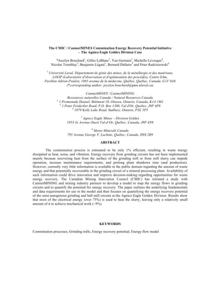
The information from the case study, presented in Figure 5 and Figure 6, revealed that most of the
power used is transferred to the enthalpy flows carried by the slurry streams, i.e. 68.9% and 81.9% for the
SAG and ball mill respectively, or 75.4% for the overall circuit. This was observed by an average
temperature increase between the feed and product streams of roughly 24°C in the SAG mill and 16°C in
the ball mill.
The most difficult value to measure corresponded to the SAG ore feed temperature. Sensors were
installed to record air temperature measurements in two locations: i) near the conveyor feeding the SAG
mill, and ii) in the dome where the ore is stored. It was estimated that these measurements could be used as
surrogate values for the ore temperature. However, readings using a laser temperature gun revealed that the
ore temperature values using this approach would be overestimated. Thus, the analysis was conducted by
using the outdoor temperature indexed by 6°C to account for the ore being warmer when extracted from
underground, even following the storage period.
In the SAG mill analysis, it can also be seen that the third largest share of power corresponds to
the heat used for water evaporation (8.3%). However, the evaporative heat loss in the ball mill was much
less at 1.2%. The difference between these was due to the smaller openings on the ball mill, which limit the
air draft. Evaporative losses were difficult to quantify and were estimated in both mills by assuming an
airflow velocity of 1.5 m/s and an estimate of the dimensions of the openings where air could escape.
Transformer
Variable
Frequency
Drive
Electric
Motor
Gearbox
˙Q 1
˙Q 2
˙Q 3
˙Q 4
˙Q 5
˙Q 6
˙Q 7
˙Q 8
˙W frag˙W elec
˙m sl in h sl in
˙m air in h air in
8. Figure 5 – Distribution of the power output in the SAG mill circuit
Figure 6 - Distribution of the power output in the ball mill circuit
Heat dissipated by
transformer, 2.0%
Heat dissipated by
variable frequency
drive, 2.0%
Heat dissipated by
electric motor, 2.9%
Heat dissipated by
gearbox, 2.3%
Heat dissipated by
trunnion cooling
system, 1.7%
Heat dissipated by
convection and
radiation, 0.6%
Heat transferred to air
by water evaporation,
8.3%
Heat transferred to the
slurry, 68.9%
Work output,
11.3%
Heat dissipated by
transformer, 2.0%
Heat dissipated by
electric motor, 2.9% Heat dissipated by
gearbox, 2.4% Heat dissipated by
trunnion cooling
system, 1.2%
Heat dissipated by
convection and
radiation, 1.0%
Heat transferred to air
by water evaporation,
1.2%
Heat transferred to the
slurry, 81.9%
Work
output,
7.4%
9. The heat losses from the equipment in both the SAG and ball mills, represented by 𝑄! to 𝑄!, were
comparable because their efficiencies and power ratings are similar. Heat losses by convection and
radiation (𝑄!) were also similar in both cases, but those for the ball mill were slightly higher because of its
larger surface area resulting in a higher convective heat transfer coefficient.
Once all the heat losses were quantified, the analysis showed that the power output attributed to
mechanical work, calculated as a difference, corresponds to 11.3% and 7.4% for the SAG and ball mills
respectively, or 9.3% for the overall circuit. These values are consistent with figures of 10 to 20% reported
by Schellinger and Lalkela (1951) and Schellinger (1951), which were determined using a similar
approach. This share included losses attributed to sound and vibration from the mills and screens, which
were determined negligible and corresponded to a total power of ~1.1 kW from measurements taken at the
Goldex mill.
Recovering and using some of the identified losses could improve the efficiency of the
comminution process. Assuming 95% mill availability, the total energy available as heat adds up to 23.8
GWh for the SAG mill, and 24.9 GWh for the ball mill annually. It must be emphasised though that
thermal losses through convection and radiation, as well as those from the electric motor, gearbox,
evaporation and trunnion cooling system are de facto recovered during the cold weather period of the year
as they contribute to heating the building. This is also true for a portion of the enthalpy conveyed by the
slurry in pump boxes and in downstream processing tanks. Moreover, even the heat contained in the slurry
exiting the plant is currently being used to some extent as it contributes at preventing tailings pipe to freeze
up during the winter. This is particularly important at Goldex as tailings are either pumped to the paste
backfill plant located 700 m west of the concentrator, or at the Manitou reclaiming site through a 24 km
long pipeline. Estimating the heat recovery potential must thus factor in that most of the energy is currently
being wasted only about 6 months per year, i.e. from May to November.
The question of finding a usage for the recoverable energy still requires to be addressed for the
remainder of year. In a cyanidation plant, a heat source is required all year round to preheat elution
solution. This is not an issue at Goldex since the gold/silver bearing concentrate is not processed onsite. If
other heat consumers cannot be identified, the only option is to convert heat into electricity.
CONCLUSION
This paper introduced the energy flow mapping application developed by CanmetMINING to
assess the energy recovery potential in grinding circuits. It is based on Radziszewski's thermodynamic
comminution model (Radziszewski, 2013), and was presented using data from Agnico Eagle’s Goldex
Division. Energy flows were mapped in the two-stage grinding circuit to show that
• 68.9% and 81.9% of the electrical power input is accumulated in the discharged slurry for the SAG
and ball mill respectively, and
• 11.3% and 7.4% of the supplied power performing actual mechanical work for the SAG and ball mills
respectively.
The total energy stored as heat represents 48.7 GWh annually, a portion of which is already used
for passive heating during the winter. A substantial amount of energy is potentially available for recovery
but it can only be useful if a demand for this energy is identified. Transforming the virtual recoverable
energy into an actual “supply” is beyond the scope of this study. Future work could examine various
strategies and technologies for low grade heat recovery, such as heat pumps, heat exchangers, and CO2
power generating turbines among others. Energy recovery solutions would require retrofits in existing
plants with the purchase and installation of heat transfer/conversion equipment, which may impact
operation, metal recovery and maintenance. Thus a techno-economic assessment would be required to
determine whether the options are financially viable for heat recovery in grinding circuits. Future efforts
should also aim to determine how design practices could be adapted for future mine sites to enable smart
energy management that could benefit from this energy resource.
10. ACKNOWLEDGEMENTS
The authors would like to thank Agnico Eagle Mines and CanmetMINING for granting
permission to publish this work. Further acknowledgements have to be given to Sam Marcuson (CMIC),
Carl Weatherell (CMIC), Nabil Bouzoubaâ (CanmetMINING) for championing this R&D initiative. A
special mention has to be given to Anthony Gérard and Pierre-Claude Ostiguy (SoftdB) for providing the
analysis estimating power losses through noise and vibration.
REFERENCES
Awatey, B., Skinner, W., & Zanin, M. (2015). Incorporating fluidised-bed flotation into a conventional
flotation flowsheet: A focus on energy implications of coarse particle recovery. Powder
Technology, 275, 85-93. doi: 10.1016/j.powtec.2015.01.065.
Fekete, B., & Szekeres, A. (2015). Investigation on partition of plastic work converted to heat during
plastic deformation for reactor steels based on inverse experimental-computational method.
European Journal of Mechanics - A/Solids, 53, 175-186. doi:
http://dx.doi.org/10.1016/j.euromechsol.2015.05.002.
Fuerstenau, D. W., & Abouzeid, A. Z. (2002). The energy efficiency of ball milling in comminution.
International Journal of Mineral Processing, 67(1-4), 161-185. doi: 10.1016/S0301-
7516(02)00039-X.
Kanchibotla, S. S., Valery, W., & Morrell, S. (1999). Modelling fines in blast fragmentation and its impact
on crushing and grinding. Paper presented at the Explo ‘99–A conference on rock breaking,
Kalgoorlie, Australia.
Lessard, J., De Bakker, J., & McHugh, L. (2014). Development of ore sorting and its impact on mineral
processing economics. Minerals Engineering, 65, 88-97. doi: 10.1016/j.mineng.2014.05.019.
Levesque, M. Y., & Millar, D. L. (2015). The link between operational practices and specific energy
consumption in metal ore milling plants - Ontario experiences. Minerals Engineering, 71, 146-
158. doi: 10.1016/j.mineng.2014.11.010.
MNP. (2013). Documentation of Key Findings of the Workshop on Barriers to Green Mining Innovation in
Canada. from http://www.nrcan.gc.ca/mining-materials/publications/11792
Morrell, S. (2009). Predicting the overall specific energy requirement of crushing, high pressure grinding
roll and tumbling mill circuits. Minerals Engineering, 22(6), 544-549. doi:
10.1016/j.mineng.2009.01.005.
Nunez, E., MacPherson, G., Graffi, D., & Tuzun, A. (2009). Self-optimizing Grinding Control for
Maximising Throughput while Maintaining Cyclone Overflow Specifications. Paper presented at
the 41st Annual Meeting of the Canadian Mineral Processors, Ottawa, Canada.
Radziszewski, P. (2013). Energy recovery potential in comminution processes. Minerals Engineering, 46-
47, 83-88. doi: 10.1016/j.mineng.2012.12.002.
Radziszewski, P., & Hewitt, D. (2015). Exploring the effect of energy recovery potential on comminution
efficiency: the Glencore Raglan Mine case. Paper presented at the SAG Conference 2015,
Vancouver, British Columbia, Canada.
Schellinger, A. K. (1951). A calorimetric method for studying grinding in a tumbling medium.
Transactions AIME, 190, 518-522.
11. Schellinger, A. K. (1952). Solid surface energy and calorimetric determinations of surface energy
relationships for some common minerals. Mining Engineering, 4(4), 369-374.
Schellinger, A. K., & Lalkela, R. D. (1951). Approximation of the energy efficiency of commercial ball
mills by the energy balance method. Transactions AIME, 190, 523-524.
Silva, D. O., Vieira, L. G. M., Lobato, F. S., & Barrozo, M. A. S. (2012). Optimization of the design and
performance of hydrocyclones by Differential Evolution technique. Chemical Engineering and
Processing: Process Intensification, 61, 1-7. doi: 10.1016/j.cep.2012.07.002.
Tbaybi, H. (2015). Impact de la flottation éclair sur l’empreinte énergétique d’un circuit de broyage – Cas
de la mine Nyrstar - Langlois. (M.Sc.), Université Laval.
Tromans, D. (2008). Mineral comminution: Energy efficiency considerations. Minerals Engineering,
21(8), 613-620. doi: 10.1016/j.mineng.2007.12.003.
Tromans, D., & Meech, J. A. (2002). Fracture toughness and surface energies of minerals: Theoretical
estimates for oxides, sulphides, silicates and halides. Minerals Engineering, 15(12), 1027-1041.
doi: 10.1016/S0892-6875(02)00213-3.
Tromans, D., & Meech, J. A. (2004). Fracture toughness and surface energies of covalent minerals:
Theoretical estimates. Minerals Engineering, 17(1), 1-15. doi: 10.1016/j.mineng.2003.09.006.
Van Der Meer, F. P., & Gruendken, A. (2010). Flowsheet considerations for optimal use of high pressure
grinding rolls. Minerals Engineering, 23(9), 663-669. doi: 10.1016/j.mineng.2009.09.012.