1. 120/240VAC Transformer Kit Instruction Sheet
WARNING - Disconnect power to the system before attempting to
complete the following.
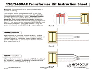
Using the wiring diagram provided, located inside the front panel, 7 6 5 4 3 2 1
determine the appropriate transformer connection. 120 or 240VAC is
connected through plug locations 5 and 7. It is important to refer to
the wiring diagram provided with the system to determine
connection. Some models have been equipped with printed circuit
boards which operate at either 120 or 240VAC (voltage at plug locations
5 and 7). If your system has been equipped with 240VAC printed circuit
board and the transformer is configured to operate at 120VAC the
system will not operate correctly. (Refer to fig. 1 and wiring diagram)
Figure 1
240VAC Connection
When configuring the transformer to operate at 240VAC, the white
w/black stripe and solid white wires must be connected (wire crimp caps
have been provided for this purpose). Refer to the wiring diagram
provided with the system for connection of the black and white w/red
stripe wires. (Refer to fig. 2)
Figure 2
120VAC Connection
When configuring the transformer to operate at 120VAC, the solid black
and white w/black stripe wires and solid white and white w/red stripe
wires must be connected. (Refer to the fig. 3)
http://www.MyPoolSpas.com
Figure 3
Wholesale Pool and Spa Parts 920-925-3094
85-0056A Rev.3 12.01