2. Content
Content
1 Introduction ...........................................................................................3
2 Install and update driver .......................................................................4
2.1 Installation of driver using Internet..................................................4
2.2 Installation of driver from disk.........................................................4
3 Connecting the terminal to the PLC system .........................................5
3.1 Settings in the CIMREX PROG .........................................................5
3.2 Connecting the terminal to the Profibus DP network......................7
3.3 Communication settings for the IFC PBDP card ..............................8
3.4 Cable to PROFIBUS-DP ....................................................................8
3.5 Technical data ...................................................................................8
3.6 Description of the PLC program section ..........................................9
4 Addressing ...........................................................................................18
5 The HMI profile...................................................................................20
5.1 The data exchange ..........................................................................20
5.2 The request and response containers .............................................21
5.3 The index structure.........................................................................22
6 Efficient communication .....................................................................24
6.1 Signals affecting the communication time......................................24
6.2 How to make the communication more efficient...........................25
7 Appendix..............................................................................................26
7.1 Error messages................................................................................26
3. Introduction
3
1 Introduction
This manual describes how the SIMATIC S7 PLC system is connected to
the terminals in the Cimrex series via the fieldbus Profibus DP. Address-
ing of an item in the PLC system is done in the normal Siemens way. For
information about the PLC system we refer to the manual for the current
system.
The terminals support the systems in the SIMATIC S7 300 and 400 series.
The expansion card IFC PBDP must be installed in the terminal.
See the IFC PBDP manual.
4. Install and update driver
4
2 Install and update driver
When installing CIMREX PROG the drivers available at the time of release
are installed too. A new driver can be added into CIMREX PROG either
with CIMREX PROG using an Internet connection or from diskette. A
driver can be updated to a newer version in the same ways.
2.1 Installation of driver using Internet
To update available drivers to the latest version or to install new drivers
you can use the function Update terminal drivers, from Internet in the File
menu in CIMREX PROG. All projects must be closed before this function
is used and the computer must be able to make an Internet connection.
You don’t need a browser. When the connection is established a list is
shown with all drivers that can be downloaded from Internet to the com-
puter. The list shows the version number of available drivers and the ver-
sion number of installed drivers. Mark the driver/drivers you want to
install in the CIMREX PROG. The function Mark Newer will mark all
drivers that are available in a newer version than the one installed and the
drivers not installed. Then you select Download. Each driver is approxi-
mately 500 kb and it is ready to use when the download is ready.
2.2 Installation of driver from disk
To update available drivers to the latest version or to install new drivers
you can use the function Update terminal drivers, from Disk in the File
menu in CIMREX PROG. All projects must be closed before this function
is used. Select the folder with the new driver and choose to open the mpd-
file. A list is shown with all drivers that can be installed showing the ver-
sion number of available drivers and the version number of installed driv-
ers. Mark the driver/drivers you want to install in the CIMREX PROG.
The function Mark Newer will mark all drivers that are available in a new-
er version than the one installed and the drivers not installed. Then you
select Install.
How to select the SIMATIC S7 ProfibusDP driver in the project and how
to transfer it to the terminal are described in chapter 3.
5. Connecting the terminal to the PLC system
5
3 Connecting the terminal to the
PLC system
3.1 Settings in the CIMREX PROG
For communication with SIMATIC S7 PLC system via the fieldbus
Profibus DP the following settings must be made in the programming tool
CIMREX PROG.
Driver selection
Choosing New in the File menu creates a new project and the dialog
Project Settings is shown. In an existing project, the dialog is shown by
selecting Project Settings in the File menu.
Press Change… under Controller system to get the choice list of available
drivers. Choose Brand name, Protocol and Model and then press OK.
Press OK again to confirm the project settings.
6. Connecting the terminal to the PLC system
6
Communication setup
The settings for the communication between the terminal and the PLC
system are done under Peripherals in the Setup menu. Mark either slot 1
or slot 2 depending on which slot the expansion card IFC PBDP is installed
in, and press Edit. Select IFC PBDP and press OK.
Mark IFC PBDP in Peripherals and press Edit to state the settings for the
HMI profile. State the size of the input and output area in bytes.
Default settings is 32 bytes.
Driver configuration
Mark selected driver (SIMATIC S7-series) and press Edit to select Data
format.
Note!
If Multi DB is supported W#16#FFFF must be entered at db_address in the HMI profile.
If Single DB is supported and if you want to use another DB number than the predefined
where DBnr=51 (hex 33) must a new DBno be entered at db_address. See also separate
description of the HMI profile.
7. Connecting the terminal to the PLC system
7
Transfer the driver to the terminal
The selected driver is down-loaded into the terminal when the project is
transferred to the terminal. Choose Project in the Transfer menu.
There are three alternatives when the driver is downloaded into the termi-
nal.
3.2 Connecting the terminal to the
Profibus DP network
With the expansion card IFC PBDP, the terminal can then be connected to
a Profibus DP network as a slave. The PLC system in the network most be
loaded with a program handling the communication between the termi-
nal and the PLC system.
Function Description
Never The driver is not down-loaded and the existing driver in the
terminal is used.
Always The driver is down-loaded every time the project is trans-
ferred.
Automatic The driver is down-loaded if the driver in the terminal is not
the same as the selected driver in the project. If it is the
same the driver is not down-loaded.
8. Connecting the terminal to the PLC system
8
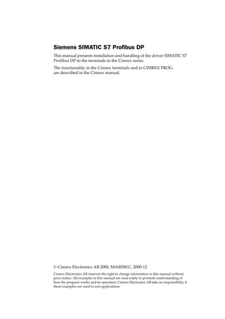
3.3 Communication settings for the
IFC PBDP card
1. Connector for the communication cable.
2. Bus termination. Set to ON on the first and last units in the network.
The first unit in the network often is the master unit in the PLC sys-
tem.
3. 1: Red, ERR, Configuration or communication error. The LED is red
until the unit is configured, Indicates time out.
2: Green, PWR, Power supply 5 VDC OK.
3: Green, DIA, Diagnostic error, not used.
4. State the station number.
3.4 Cable to PROFIBUS-DP
3.5 Technical data
The cable Unitronic-Bus L2/F.I.P is tested and has the following
performance:
I/O area size 32-200 byte
Baudrate 9600 bit/s - 12 MBit/s
Identity code 1002
Max. number of nodes without repeater 32
Max. number of nodes with repeater 96
Max. cable length (with repeater) 3000m, 9.6 kb
Max. cable length (without repeater) 200m, 12 Mb
Capacitance 30 nF/km
Impedance 150 Ohm (3-20 MHz)
Resistance 115 Ohm/km
0 01 12 2
3
3
4
56
4
56
7
7
8
8
9 9
Term. Stn. no.
MSB LSB
ON
1
1 2 3 4
1
2
3
(3) RxD/TxD-P
(5) DGND
(8) RxD/TxD-NRxD/TxD-N (8)
DGND (5)
RxD/TxD-P (3)
Protective
Ground
Shield
Protective
Ground
Station 2Station 1
9. Connecting the terminal to the PLC system
9
3.6 Description of the PLC program
section
HMI-profile, with consistent data
Used for the CPU types that support the data block SFC14 and SFC15, see
information for respective type from Siemens.
The PLC program section consists of three function blocks plus one block
(OB1) that calls the function block 110.
Program block
The PLC program section, available on the type diskette, contains three
function blocks, two system blocks and one main program.
* SFC 14 and SFC 15 are not valid for all PLC types, see Siemens informa-
tion for more detailed information.
Consistent data = whole messages are read and write in one scan.
Function block Description
OB1 Main program. Calls the function block 110 with DB110.
FB 110 This block is called by the OB1 and handles the HMI profile.
FB 111 This block reads one index.
FB 112 This block writes one index.
DB 51 Data block used for analog signals.
DB 110 Data block, instance data block for FB 110 (Siemens standard)
DB 111
Data block used for back up copies of memory words and flags. If
DB 111 already is in use in current application a new DB must con-
tain a minimum of 56 words.
DB 112 Data block where in/out area is stored (must be at least 64 words)
SFC 14
Data block “DPRD_DAT” system block for reading/writing consis-
tent data*.
SFC 15
Data block “DPWR_DAT” system block for reading/writing consis-
tent data*.
Note!
The following data types are used in the HMI profile: MW200-MW255, T99, which
contains words, bytes and bits.
10. Connecting the terminal to the PLC system
10
The figure below shows how the “HMI profile” is placed in the PLC
program.
( )
( )
][END
Application
11. Connecting the terminal to the PLC system
11
The main program, OB1
OB1 is the main program where the parameters are defined for calling the
other function blocks. The following parameters are defined for the FB110,
SFC14 and SFC15:
For more information about the parameters, refer to the manual for
SIMATIC S7.
Examples of configuration
In those examples we use Siemens PLC system S7 and the PLC projects
(HMI-conc) on the type diskette. The example describes in which order
you make the settings and connections to get the correct communication.
GDS files and HMI profile (PLC project) are available also on the webb.
Parameter Description
SFC14
“DPRD_DAT”
LADDR Input address (hex) where data from module can
be read.
RET_VAL Error code.
RECORD The place to store data that is read.
FB110 RECORD_DP_RD The first input byte from where input data can be
read. Default is 0 hex (0 dec).
RECORD_DP_WD The first output byte from where output data can
be read. Default is 20 hex (32 dec).
RECORD_DB Data block number where input/output data is
stored. Default 70 hex (112 dec).
CON_LEN State the length of the request container and
response container. Must be the same as the set-
ting in the terminal. Default is 20 hex (32 dec).
DB_ADDRESS If Single DB: State the number of the data block
used.
If Multi DB: State W#16#FFFF to the DB address.
Default 33 hex (51dec).
DB_FLAG_COPY State the data block used for backup copy of flag
words. Default 6F hex (111 dec).
SFC15
“DPWR_DAT”
LADDR Output address (hex) where data from module can
be written.
RET_VAL Error code.
RECORD The place to store data that should be written to
the module.
12. Connecting the terminal to the PLC system
12
Alternative 1: Current PLC project (HMI profile) for S7-315-2DP CPU
For procedure description we refer to the manual for handling S7-PLC
and STEP7 from Siemens.
1. Install the terminal and IFC-PBDP according to the Installation man-
ual delivered with the terminal.
2. Configure the terminal with the software package CIMREX PROG.
3. Copy the .GSD files from the diskette to the GSD-library in STEP7
(normally STEP7S7dataGsd...).*
4. Update hardware library in STEP7 Hardware.
5. Copy the PLC project from the diskette to the computer, (normally
STEP7S7proj...).*
6. Start STEP7, open the PLC project.
7. Start Hardware STEP 7.
8. Check the hardware.
- CPU type, DP Master, E700 DP slave no. (Profibus DPAdditional
Field DeviceB+BMAC-Exx0withIFC-P).
Note! Station number for the IFC PBDP card must be the same as in the
Hardware configuration.
9. Check DP slave properties.
- I/O type:=Input/Output
- Address: for Input and Output area, default=64 in the HMI profile.
- Length: for Input and Output area, default=32 in the HMI profile.
- Unit: for Input and Output area=Byte.
- Consistent via:=Total Length.
10.Transfer the Hardware configuration to the S7 system.
11.Transfer the PLC program section to the S7 system.
Note! If Multi DB is used the DB address must be W#16#FFFFin FB110,
single DB is default in the HMI profile.
12.Connect the cable between the S7 system and the IFC PBDP card in the
terminal.
13.Put the S7 system and the terminal in run mode.
* GDS files and HMI profile (PLC project) are available also on the webb.
Terminal with
the IFC PBDP
SIMATIC S7
PROFIBUS DP
card installed
13. Connecting the terminal to the PLC system
13
Alternative 2: Complete, current or new PLC project together with HMI profile
1. Install the terminal and IFC-PBDP according to the Installation man-
ual delivered with the terminal.
2. Configure the terminal with the software package CIMREX PROG.
3. Copy the .GSD files from the diskette to the GSD-library in STEP7
(normally STEP7S7dataGsd...).*
4. Update hardware library in STEP7 Hardware.
5. Copy the PLC project from the diskette to the computer, (normally
STEP7S7proj...).*
6. Start STEP7, open the PLC project.
7. Start Hardware STEP 7.
8. Configure the hardware.
- Select Rail, CPU type, DP Master, Exx0 DP slave no. (Profibus
DPAdditional Field DeviceB+BMAC-Exx0 with IFC-P).
Note! Station number for the IFC PBDP card must be the same as in the
Hardware configuration.
9. Configure DP slave properties.
- Select Universal Module to the IFC PBDP slave (drag and drop).
- Select I/O type:=Input/Output
- State Address: for In- & Output area, default=64 in the HMI profile.
- State Length: for In- & Output area, default=32 in the HMI profile.
- Select Unit: for Input and Output area=Byte.
- Select Consistent via:=Total Length.
10.Transfer the Hardware configuration to the S7 system.
11.Open the PLC programs (block) for both projects (the new or current
and the HMI profile project).
- Copy the blocks from the HMI profile project (OB1, FB110, FC111,
FC112, DB51, DB110, DB111, DB112 SFC14 and SFC15).
Note! If Multi DB is used the DB address must be W#16#FFFFin FB110,
single DB is default in the HMI profile.
- Check that the call in OB1 is correct defined.
12.Transfer the PLC program section to the S7 system (mark all blocks
and select Download).
13.Connect the cable between the S7 system and the IFC PBDP card in the
terminal.
14.Put the S7 system and the terminal in run mode.
* GDS files and HMI profile (PLC project) are available also on the webb.
14. Connecting the terminal to the PLC system
14
HMI profile without consistent data
Can be used by all CPU types, see information from Siemens.
The PLC program section consists of three function blocks plus one block
(OB1) that calls the function block 110.
Program block
The PLC program section, available on the type diskette, contains three
function blocks and one main program.
The following figure shows how the HMI profile in OB1 is placed in the
PLC program.
Function block Description
OB1 Main program. Calls the function block 110 with DB110.
FB 110 This block is called by the OB1 and handles the HMI profile.
FC 111 This block reads one index.
FC 112 This block writes one index.
DB 51 Data block used for analog signals.
DB 110 Data block, instance data block for FB 110 (Siemens standard)
DB 111
Data block used for back up copies of memory words and flags. If
DB 111 already is in use in current application a new DB must con-
tain a minimum of 56 words.
( )
( )
][END
Application
15. Connecting the terminal to the PLC system
15
The following data types are used in the HMI profile: MW200-MW255,
T99, which contains words, bytes and bits.
The main program, OB1
OB1 is the main program where the parameters are defined for calling the
other function blocks. The following parameters are defined for the func-
tion block 110:
For more information about the parameters, refer to the manual for
SIMATIC S7.
Examples of configurations
In these examples we use Siemens PLC system S7 and the PLC program
on the type diskette. The example describes in which order you make the
settings and connections to get the correct communication.
Parameter Description
FB_IN_OFFSET State the address to the first byte in the response container in the
PROFIBUS area. Default is 40 hex (64 dec).
FB_OUT_OFFSET State the address to the first byte in the request container in the
PROFIBUS area. Default is 40 hex (64 dec).
CON_LEN State the length of the request container and response container.
Must be the same as the setting in the terminal. Default is 20 hex
(32 dec).
DB_ADDRESS State the number of the data block used. Default is 33 hex (51
dec).
DB_FLAG_COPY State data block address used. Default is 6F hex (111 dec).
Terminal with
the IFC PBDP
SIMATIC S7
PROFIBUS DP
card installed
16. Connecting the terminal to the PLC system
16
Alternative 1: Current PLC project (HMI profile) for S7-315-2DP CPU
For procedure description we refer to the manual for handling S7-PLC
and STEP7 from Siemens.
1. Install the terminal and IFC-PBDP according to the Installation man-
ual delivered with the terminal.
2. Configure the terminal with the software package CIMREX PROG.
3. Copy the .GSD files from the diskette to the GSD-library in STEP7
(normally STEP7S7dataGsd...).*
4. Update hardware library in STEP7 Hardware.
5. Copy the PLC project from the diskette to the computer, (normally
STEP7S7proj...).*
6. Start STEP7, open the PLC project.
7. Start Hardware STEP 7.
8. Check the hardware.
- CPU type, DP Master, E700 DP slave no. (Profibus DPAdditional
Field DeviceB+BMAC-Exx0withIFC-P).
Note! Station number for the IFC PBDP card must be the same as in the
Hardware configuration.
9. Check the DP slave properties.
- Address: for Input and Output area, default=64 in the HMI profile.
- Length: for Input and Output area, default=32 in the HMI profile.
10.Transfer the Hardware configuration to the S7 system.
11.Transfer the PLC program section to the S7 system.
Note! If Multi DB is used the DB address must be W#16#FFFFin FB110,
single DB is default in the HMI profile
12.Connect the cable between the S7 system and the IFC PBDP card in the
terminal.
13.Put the S7 system and the terminal in run mode.
* GDS files and HMI profile (PLC project) are available also on the webb.
17. Connecting the terminal to the PLC system
17
Alternative 2: Complete current or new PLC project together with HMI profile
For procedure description we refer to the manual for handling S7-PLC
and STEP7 from Siemens.
1. Install the terminal and IFC-PBDP according to the Installation man-
ual delivered with the terminal.
2. Configure the terminal with the software package CIMREX PROG.
3. Copy the .GSD files from the diskette to the GSD-library in STEP7
(normally STEP7S7dataGsd...).*
4. Update hardware library in STEP7 Hardware.
5. Copy the PLC project from the diskette to the computer, (normally
STEP7S7proj...).*
6. Start STEP7, open the PLC project.
7. Start Hardware STEP 7.
8. Configure the hardware.
- Select Rail, CPU type, DP Master, Exx0 DP slave no. (Profibus
DPAdditional Field DeviceB+BMAC-Exx0 with IFC-P).
Note! Station number for the IFC PBDP card must be the same as in the
Hardware configuration.
9. Configure the DP slave properties.
- Select IN/OUT: 32 bytes (16 words) to the IFC PBDP slave (drag and
drop.
- State Address: for In- & Output area, default=64 in the HMI profile.
- State Length: for In- & Output area, default=32 in the HMI profile.
10.Transfer the Hardware configuration to the S7 system.
11.Open the PLC programs (block) for both projects (the new or current
and the HMI profile project).
- Copy the blocks from the HMI profile project (OB1, FB110, FC111,
FC112, DB51, DB110 and DB111.
Note! If Multi DB is used the DB address must be W#16#FFFFin FB110,
single DB is default in the HMI profile.
12.Transfer the PLC program section to the S7 system (mark all blocks
and select Download).
13.Connect the cable between the S7 system and the IFC PBDP card in the
terminal.
14.Put the S7 system and the terminal in run mode.
* GDS files and HMI profile (PLC project) are available also on the webb.
18. Addressing
18
4 Addressing
The terminal can handle the following data types in the PLC system:
The project memory decides the max length of the DB (data block) in
SIMATIC S7. The terminal can access all DB in the PLC system.
All data types consist of byte areas. Addressing is always byte-specific, re-
gardless of wether it is 1, 16, 32 bits.
The addresses are always decimal 0- 65535.
For information about instructions in the PLC system we refer to the man-
ual for the PLC system.
Digital signals
For digital signals you state current bit in the byte. For example I50.3 bit 3
means bit 3 in input byte 50.
* Multi DB
** Single DB
xxxx=address (minimum value = 0 depend, maximum value depend on
the PLC-system) b=bit number 0-7. No = data block number (0-255).
Name Data type English Data type German
Flag F M
Output Q A
Input I E
Data block DB DB
Note!
If you try to access an undefined data block in the PLC-system, the PLC-system will
stop.
Data type
English
Addressing
example, English
Data type
German
Addressing
example, German
Ixxxx.b <I3.7> Exxxx.b <E3.7>
Qxxxx.b <Q1.3> Axxxx.b <A1.3>
Fxxxx.b <F5.6> Mxxxx.b <M5.6>
DBno.DBX.xxxx.b* <DB51.DBX23.7> DBno.DBX.xxxx.b* <DB51.DBX23.7>
DBXxxxx** <DBX23.7> DBXxxxx** <DBX23.7>
Note!
Writing bits from the terminal to the PLC is done in three steps:
1. Reading the whole byte from the PLC to the terminal.
2. The current bit is set/reset in the terminal.
3. Writing of the whole byte from the terminal to the PLC.
During the time it takes for the terminal to do the three steps the PLC may not change
the other bits in the current byte since it will be overwritten.
19. Addressing
19
Analog signals
For 16-bit numbers, you state the suffix W; for example MW100 means 2
bytes from memory byte 100-101.
* Multi DB
** Single DB
xxxx=address (minimum value = 0 depend, maximum value depend on
the PLC-system) no=data block number (0-255) and adr=data word with-
in the data base 0~8 kbyte (see current PLC type).
For 32-bit numbers, you state the suffix D; for example MD100 means 4
bytes from memory byte 100-103.
* Multi DB
** Single DB
xxxx=address (minimum value = 0 depend, maximum value depend on
the PLC-system), no=data block number 0-255 and adr=data word within
the data base 0~8 kbyte (see current PLC type).
Data type
English
Addressing
example, English
Data type
German
Addressing
example, German
IWxxxx <IW231> EWxxxx <EW231>
QWxxxx <QW2> AWxxxx <AW2>
FWxxxx <FW101> MWxxxx <MW101>
DBno.DBWadr* <DB23.DBW49> DBno.DBWadr* <DB23.DBW49>
DBWxxxx** <DBW49> DBWxxxx** <DBW49>
Note!
When storing ASCII values in 16-bit numbers the eight most significant bits contain the
first ASCII code and the eight least significant bits contain the second ASCII code.
Data type
English
Addressing
example, English
Data type
German
Addressing
example, German
IDxxxx <ID21> EDxxxx <ED21>
QDxxxx <QD34> ADxxxx <AD34>
FDyyyy <FD39> MDyyyy <MD39>
DBno.DBDadr* <DB23.DBD54> DBno.DBDadr* <DB23.DBD54>
DBDxxxx** <DBD54> DBDxxxx** <DBD54>
20. The HMI profile
20
5 The HMI profile
This chapter describes setup of the HMI profile, and is for the benefit of
readers who want to learn more about data exchange via the HMI profile.
The HMI profile allows exchange of an unlimited amount of data, and
also allows the terminal to access all type of devices in the PLC system.
Together with the card a type diskette is supplied containing PLC pro-
gram for communication with different PLC system.
PROFIBUS-DP allows a maximum byte length of 200 bytes in and 200 out
per station. The HMI profile uses an input area and an output area. These
areas are hereafter referred to as containers. The HMI uses the container
to access the PLC.
For more detailed information on the HMI profile see the specifications
from the Profibus Organisation.
5.1 The data exchange
– The terminal is a slave in the PROFIBUS-DP net.
– The PLC system is the master.
– The terminal requests data from the PLC system through the input con-
tainer.
– The PLC program serves the terminal with data through the output
container.
– Handshaking between the terminal and the PLC system is performed
through a Control byte in the containers.
– The terminal can access all types of PLC devices.
– When the terminal toggles the control byte, the PLC knows that the ter-
minal wants to exchange data.
()
()
PLCHMI
][END
PROFIBUS DP
DP slave DP master
ResponseRequest
Containers
21. The HMI profile
21
5.2 The request and response containers
The container starts at address 0 with the control byte. The control byte is
used for handshaking and for communication failure detection. Address-
es 1-3 are reserved for Fast bytes. These are not used in the terminal.
Addresses 4 to 200 are used for communication. The terminal put indexes
here (3 byte each) that refer to the PLC devices that the terminal wants to
read or write. The PLC system, on the other hand, will put the data here
from the PLC devices that the terminal has asked for. If the terminal wants
to write to a PLC device, the data is stored immediately after the index.
The control byte in the request container
The request container contains a message from the terminal to the PLC
system.
Request
The request byte is used for handshaking between the units. The bit tog-
gles when the terminal wants information for the PLC system.
COM
The COM bit is set by the terminal. If communication breaks the bit will
be reset.
Request container Response container
00 Control byte 00 Control byte
01 Not used 01 Not used
02 Not used 02 Not used
03 Not used 03 Not used
04 Index 1 Read 04 Data for index 1
05 - - 05 - -
06 - - 06 Data for index 2-
07 Index 2 Read 07 - -
08 - - 08 - -
09 - - 09 - -
10 Index 3 Write 10 - -
11 - - 11 - -
12 - - 12 - -
13 Data byte for index 3 13 Free
14 Data byte for index 3 14 Free
....200 ....200 Free
7 6 5 4 3 2 1 0
Request COM Toggle Error Acknowledge bits, not used
22. The HMI profile
22
Toggle
The toggle bit is always set to the opposite value as the toggle bit in the
request container.
Error
This bit is not used.
Acknowledge
These bits are not used.
The control byte in the response container
The response container contains the response from the PLC system to the
HMI terminal.
Response
Is set to the same value as request when data is ready for transfer to the
HMI terminal.
COM
The OM bit is set by the PLC program. If communication breaks the bit
will be reset.
Toggle
The toggle bit is always set to the same value as the toggle bit in the re-
quest container.
Error
This bit is not used.
Action
These bits are not used.
5.3 The index structure
The index is built up of 3 bytes. The index contains 4 parts of information:
– If the device should be read or written.
– Which type of device (input, data register, timer etc.)
– Number of device (e.g. input 5).
– Data length (from one bit up to 16 bytes).
7 6 5 4 3 2 1 0
Response COM Toggle Error Acknowledge bits, not used
7 6 5 4 3 2 1 0
Write Ln2 Ln1 Ln0 PLC device type
Index number bit 15-8
Index number bit 7-0
23. The HMI profile
23
PLC device type
States the type of PLC device according to the following table.
Ln0-Ln2
States the data length according to the following table.
Sequence of events
– The terminal decides which variables are to be read/written.
– The terminal toggles the request flag in the control byte.
– In the next PROFIBUS cycle, the PLC notices that the request flag has
been changed.
– For each read index, the values of the requested devices are copied to
the response container.
– Then the response flag in the response container is set to the same value
as the request flag in the request container.
– In the next PROFIBUS cycle, the terminal notices that the request flag
and the response flag are the same which means that there is data for
the terminal.
– The received values will now be used by the objects in the terminal.
Number
Data type
English
Data type
German
1 F M
2 I E
3 Q A
8 DB DB
Ln2 Ln1 Ln0 Length
0 0 0 bit
0 0 1 1 byte
0 1 0 2 bytes
0 1 1 4 bytes
1 0 0 6 bytes
1 0 1 8 bytes
1 1 0 12 bytes
1 1 1 16 bytes
24. Efficient communication
24
6 Efficient communication
To make the communication between the terminal and the PLC system
quick and efficient the following should be noted about how the signals
are read and what that can be done to optimize the reading.
6.1 Signals affecting the communication
time
It is only signals to objects in the current block that are read continuously.
Signals to objects in other blocks are not read, that is the number of blocks
does not affect the communication time.
Besides the signals to objects in the current block, the terminal is continu-
ously reading the following signals from the PLC system:
Display signals
Block print-out signals
LED registers
Alarm signals
Remote acknowledge signals on alarms and alarm groups
Login signal
Logout signal
Trend registers at the sample points
Bargraph registers if using min/max indicators
New display register
Buzzer register
Backlight signal
Cursor control block
Recipe control block
Library index register
Index registers
PLC clock register if the PLC clock is used in the terminal
List erase signal
No protocol control register
No protocol on signal
Signals not affecting the communication time
The following signals do not affect the communication time:
– Signals linked to function keys
– Time channels
– Objects in the alarm messages
25. Efficient communication
25
6.2 How to make the communication more
efficient
Group PLC signals consecutively
The signals from the PLC system are read most rapidly if all signals in the
list above are consecutive. If for example, 100 signals are defined, it is
quickest to read these if they are linked to, for example, M0.0-M11.7. If the
signals are spread out (e.g. I0.4, Q30.0, F45.3 etc.) the updating is slower.
Efficient block changes
Block changes are carried out most rapidly and efficiently through the
block jump function on the function keys or through a jump object. "Dis-
play signals" in the block header should only be used when the PLC sys-
tem is to force the presentation of another block. The "New Display"
register can also be used if the PLC system is to change the block. This
does not affect communication as much as a larger number of "Display
signals".
Use the clock of the terminal
An extra load is put on communication if the clock of the PLC system is
used since the clock register must be read up to the terminal. Download-
ing of the clock to the PLC system also creates an extra load. The interval
between downloadings should therefore be as long as possible.
Packaging of signals
When the signals are transferred between the terminal and the PLC sys-
tem, all signals are not transferred simultaneously. Instead they are divid-
ed into packages with a number of signals in each package. To decrease
the number of packages that have to be transferred and make the commu-
nication faster this number has to be considered. The number of signals in
each package depends on the used driver. In the SIMATIC S7 Profibus DP
driver the number is 8 for analog devices and 128 for digital devices.
To make the communication as fast as possible the number of packages
has to be minimized. Consecutive signals require a minimum of used
packages but it is not always possible to have consecutive signals. In such
cases the so-called waste between two signals has to be considered. The
waste is the maximum distance between two signals you can have and
still keep them in the same package. The waste depends on the used driv-
er. In the SIMATIC S7 Profibus DP driver the number is 2 for analog de-
vices and 24 for digital devices.
Signal
Used
; ; ; ; ;
Waste
26. Appendix
26
7 Appendix
7.1 Error messages
Error messages from the PLC system. The code is shown on the display of
the terminal.
Error message Description
“Com error” Communication error
“Wrong fieldbus type” Incorrect IFC PBDP card installed
“Fieldbus no response” No response from the IFC PBDP card
“No IFC-PBDP-card” No IFC PBDP card installed in the terminal