1. 1
CHAPTER: 1 COMPANY PROFILE
1.1 INTRODUCTION
We are carrying out Project Work in FINE CAST Pvt. Ltd., V.U. Nagar.
Fig. 1.1 Company Logo
It was established in 1973.
The company is ISO 9001: 2008 certified.
It is Grey Cast Iron Foundry Industry.
Contact details: www.finecast.co.in
Its Current Customers are Elecon, Ingersollrand, etc.
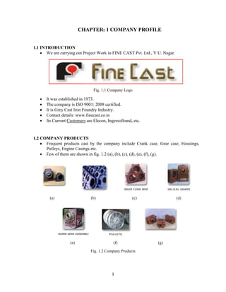
1.2 COMPANY PRODUCTS
Frequent products cast by the company include Crank case, Gear case, Housings,
Pulleys, Engine Casings etc.
Few of them are shown in fig. 1.2 (a), (b), (c), (d), (e), (f), (g).
(a) (b) (c) (d)
(e) (f) (g)
Fig. 1.2 Company Products
2. 2
1.3 AVAILABLE FACILITIES
Tilting type Induction Furnaces- two (1000 kg each); Fig. 1.3 (a)
Cupola Furnace; Fig. 1.3 (b)
Tilting type Pouring Ladles-three (having different capacity); Fig. 1.3 (c)
Sand Mixing Muller-three (having different capacity); Fig. 1.3 (d)
Conveyor for molding sand
Molding Machines (of different capacity of ramming pressures); Fig. 1.3 (e)
Carbon Equivalent Meter; Fig. 1.3 (f)
Knock out Machine; Fig. 1.3 (g)
Shot blasting Machines
Sand Reclamation unit and bucket type conveyor
Various Grinders in Fettling shop; Fig. 1.3 (h)
Sand Testing Laboratory (Including Sand siever, Sand rammer, Hot plate, Active clay
setup, Compactibility scale, Moisture content tester, Green compressive strength
tester, Permeability tester, Mould & core hardness tester); Fig 1.3.1 (a) to (i)
(a) (b) (c)
(d) (e) (f)
(g) (h)
Fig. 1.3 Molding & Other Equipments
Courtesy of FINE CAST PVT. LTD.
4. 4
CHAPTER: 2 PROBLEM DEFINITION
2.1 INTRODUCTION
Company has Casting coded EP20, which has very high rejection rate. It is shown in
fig. 2.1.
This is because it is hand molded owing to its size.
We are intended to modify their gating and feeding systems so that its rejection rate
may reduce.
It has 240 kg weight. 2 or 3 rejections affect a lot in overall yield and lead to heavy
losses.
2.2 REJECTION RATE
The frequency of the order for EP20 is 15 castings per month.
Monthly Rejection rate of this casting is shown in fig. 2.2.
2.3 DEFINITION
“Design Optimization of Gating System and Casting Simulation for Cast Iron”
Fig. 2.1 EP20 Casting Fig. 2.2 Rejection Rate
Courtesy of FINE CAST PVT. LTD.
0
1
2
3
4
5
6
May '13 June '13 July '13 August '13
RejectionQty
Month
5. 5
CHAPTER: 3 METHODOLOGY
1. Study of Defects in the cast parts
2. Analyzing probable causes of frequently occurring defects
3. Analyzing rejection rates due to defects for casting
4. Review of Literature for Casting Simulation
5. Solid Modeling of casting using Pro-E
6. Manual Gating system and Riser Designs for casting
7. Study of the casting simulation software
8. Solidification Simulation for Proposed Method & its Optimization
9. Comment on other frequently occurring defects
6. 6
CHAPTER: 4 LITERATURE REVIEW
Sr.
No.
Author Title Conclusion/Abstract Journal
1 K.D.
Carlson,
R.A.
Hardin,
Shouzhu Ou
& C.
Beckermann
Development
of new feeding
distance rules
using casting
simulation:
Part 1.
Methodology
- Developed a methodology to relate
measured shrinkage porosity levels
in steel castings to predictions
from casting simulation, to
determine feeding distances.
- Experimental shrinkage level is
expressed as ASTM shrinkage X-
ray level.
- Predicted value for this is expressed
in terms of Niyama criterion.
Metallurgical
and materials
transactions B;
vol 33 B,
October 2002-
731
2 K.D.
Carlson,
R.A.
Hardin,
Shouzhu Ou
& C.
Beckermann
Development
of new feeding
distance rules
using casting
simulation:
Part 2. The
new rules
- Developed the rules to produce
radiographically sound castings.
- Rules for riser zone length, end
zone length, end effect feeding
distance and lateral feeding
distance for top risers, and feeding
distance for side risers are
developed.
- Extension of these rules for the
provision of feed-aids such as
chills.
Metallurgical
and materials
transactions B;
vol 33 B,
October 2002-
741
3 B. Ravi,
R.C. Creese
& D.
Ramesh
Design for
casting- A new
paradigm for
preventing
potential
problems
- Often, product design causes severe
problems at the casting stage, in
terms of defects and difficulties in
molding.
- Significant design modifications at
this stage lead to heavy losses.
- Simulation provides the way out by
virtual trials during the very design
stage of product.
Transactions
of the
American
Foundry
Society, 107,
1999
4 K. Singh,
P.K. Reddy,
D. Joshi, K.
Subburaj &
B. Ravi
3D junctions in
castings:
Simulation
based DFM
Analysis and
Guidelines
- Casting defects, which can’t be
eliminated by changes in tooling
and process parameters, can be
attributed to poor design of the part
wrt manufacturability.
- These defects can be predicted by
simulation, and corrected by minor
changes in part design.
- Junctions are regions of high
thermal concentration so changes
must be made in them by
referring result of simulation.
INAE-
ICAMT 2008,
Feb. 6-8, 2008
7. 7
5 B.G.
Thomas
Issues in
thermal-
mechanical
modeling of
casting
processes
- Stress modeling begins with a
coupled, transient heat transfer
analysis, including solidification,
shrinkage dependent interfacial heat
transfer, & fluid flow effects.
- Numerical calculation of stress-strain
that arises during solidification is
important to predict surface shape
and cracking problems.
Iron & Steel
inst. Of
Japan
International,
Vol.35, No.
6,
1995,pp.737-
743
6 Mark Jolly Casting
Simulation:
How well do
reality and
virtual casting
match? State of
the art review
- The interface heat transfer co-
efficient is probably the most
fudged part of casting modeling.
- Defects must be represented
graphically so that anyone can
easily interpret that.
Int. J. Cast
Metals Res.,
2002, 14,
303-313
7 Z. Guo, N.
Saunders,
A.P.
Miodownik
& J.-Ph.
Schille
Modeling of
materials
properties and
behavior
critical to
casting
simulation
- Development and calibration of
software used to calculate thermo-
physical properties of the mold-
metal and interface.
- These properties must be known
accurately as they are needed in
solidification simulation as inputs.
- These properties alter substantially
even by small change in
composition.
Materials
science and
engineering
A 413-414
(2005) 465-
469
8 Dr. B. Ravi Casting
Simulation and
Optimization:
Benefits,
Bottlenecks,
and best
Practices
- Casting simulation can predict
location of internal defects and
visualize mold filling, solidification
and cooling.
- Casting simulation can enhance the
productivity and success of method
engineer, but can’t replace him.
Tech. paper
for Indian
Foundry
journal Jan.
2008 Special
issue
9 Dr. B. Ravi,
D. Joshi &
K. Singh
Part, Tooling
and method
optimization
driven by
Castability
analysis and
cost model
- Evaluation of the simulation result
using three quality indices:
moldability, fillability & feedablity.
- This evaluation leads to modified
part, tooling & method design and
in turn reduces the cost
substantially.
1. Moldability- Deviation from the
designed shape
2. Fillability- Effects of mold filling
characteristics
3. Feedability- Effects of solidification
characteristics
68th
world
foundry
congress,
Chennai, 7-
10 feb. 2008
8. 8
10 T.R.
Vijayaram,
S. Sulaiman,
A.M.S.
Hamouda &
M.H.M.
Ahmad
Numerical
simulation of
casting
solidification
in permanent
metallic molds
- Solidification simulation of casting
can be performed by FDM, FEM,
FVM and BEM.
- It can identify defective location in
the casting generated time-
temperature contours.
Journal of
materials
processing
technology
178 (2006) 29-
33
11 Dr. B. Ravi Casting
simulation-
Best practices
- Casting simulation helps in (a)
quality or yield improvement of
existing castings and (b) rapid
development of new castings.
- Input 3d part model must be as-
cast part not the machined part (in
STL format).
- As curved surface is approximated
by a no. of triangles, even a small
fillet can lead to large increase in
file size.
- So, small features can be safely
removed from CAD model,
without much affecting the result,
to reduce the computation time.
Trans. Of 58th
IFC,
Ahmedabad
(2010)
12 B. Ravi &
M.N.
Srinivasan
Feature
recognition
and analysis
for molded
components
- Methods for obtaining the solid
corresponding to the feature, based
solely on BRep, have been
developed for the design of
pattern, mold, core & core-box.
13 Dr. B. Ravi Computer
aided casting
method design,
simulation and
optimization
- Latest version of AUTOCAST is
able to create entire core model &
feeder model automatically.
- More feeders can be created by
specifying their positions. Feed-
aids can also be applied.
- Gating system can be created after
specifying the positions of gates on
the part. Sprue location is to be
specified and runners are created
automatically.
- So, design, simulation &
optimization of method layout is
easily carried out using simulation
software.
Inst. Of Indian
Foundry men
(Indore
chapter), 13
march 2008
9. 9
14 V.M.
Gopinath,
A.
Venkatesan
& A.
Rajadurai
Simulation of
casting soli.
and its grain
structure
prediction
using FEM
- In addition to temperature
distribution, grain structure of the
casting can be predicted by
extending the program to
calculate G (temp. gradient), R
(interface velo.) and dT/dt (soli.
rate).
Journal of
materials
processing
technology
168 (2005) 10-
15
15 B. Ravi &
M.N.
Srinivasan
Casting
solidification
analysis by
modulus vector
method
- Discovered a new geometry driven
method called Modulus Vector
Method for identifying hot spots &
simulations of feeding paths.
- Simulation based on this method is
less sensitive to inaccurate values
of interface heat transfer co-
efficient value.
Int. J. Cast
metals Res.
1996, 9,1-7
16 K.S. Chan,
K.
Pericleous
& M. Cross
Numerical
simulation of
flows
encountered
during mold
filling
- Described a model to simulate
flows & interface activity during
the filling of 3-d casting molds.
- The equations governing the
complex physical phenomenon of
mold filling are Navier- Stokes
equations, Continuity equation
and turbulent viscosity equation.
Appl. Math.
Modeling,
1991, vol. 15,
nov./dec.
10. 10
CHAPTER: 5 CASTING PROCESS
5.1 INTRODUCTION
It is the process of manufacturing in which molten metal is poured in the cavity,
known as mold cavity, so that solidified metal takes the shape of the cavity. The
solidified metal is called Casting and the process is called Casting Process.
Mold cavity is prepared by patterns. It is always larger in size than the actual casting.
Fig. 5.1 (a) shows various terms related to casting process.
Fig. 5.1 (a) Terms Related To Casting Process
Classification of Casting Processes is shown in fig. 5.1 (b).
Fig. 5.1 (b) Classification of Casting Processes
11. 11
5.2 CASTING PROCESS CARRIED OUT AT FINE CAST
1. Melting Practice:
As Fine Cast is producing Grey iron castings, they are equipped with a cupola and two
tilting type induction furnaces (of 1 ton melting capacity). In usual running, one induction
furnace is operated and other is prepared in terms of refractory lining. Induction furnace
is better than cupola in terms of melting time and composition control of the desired melt.
Typical charge calculation (of 1 ton) include 500 kg of bead scrap, 130 kg of steel scrap,
350 kg of return riser, 180 kg of pig iron, 8 kg of silicon, 9 kg of carbon, 800 gm of
manganese and 600 gm of INOCULATION (Graphite and Silicon- to improve
machinability and reduce chances of defects in casting). Before transferring the molten
metal into pouring ladle at 15000
c, sample melt is poured into Carbon Equivalent Meter
cup, in order to check Carbon and Silicon content. It must be within prescribed limits.
2. Sand Preparation:
Mainly Kheda and Jhagadiya sands are used as silica sand. For the cores, oil is added as
binders and mulled properly to obtain thorough and homogeneous mixture called core
sand. Cores are made manually using this sand and are allowed to set for 8 hours.
Generally, cores required tomorrow are made a day before. Previously, they were using
Molasses as binder; there core backing i.e. heating was necessary. Molding sand has
totally different composition of ingredients as compared to core sand. It uses reclaimed
sand and for one lot 15 kg of bentonite powder (to improve GCS), 1 kg of coal dust
powder (to improve gas formation) and 20 liters of water are added and the mixture is
mulled. The molding sand is conveyed to the molding machines via conveyor-belt
system.
3. Mold Making & Core setting:
Here, molding sand is rammed either manually or by machines into the molding boxes
depending upon the sizes of the castings. Machine rammers are using vibrations and
squeezing action for this purpose. Pin lifting mechanism is incorporated in the machines.
Sometimes, mold heating is also done to remove excess moisture from it. Generally, cope
part is molded with gating and riser system and venting is also provided. Cores and molds
of larger castings are painted to reduce chances of defects in castings. During this phase,
core is assembled with the molding boxes and mold is made available ready for pouring.
Mold and core hardness are frequently checked during the operation.
4. Pouring:
The ready molds are transferred to the pouring area and molten metal is poured in it from
the tilting type ladle which runs with the help of overhead crane. Pouring rate is
controlled by the operator himself. Pouring ladle also has refractory brick lining to
minimize heat losses. After completely filling the mold, riser and sprue openings are
covered with the sand to minimize heat losses.
5. Fettling & Knockout:
After the solidification of the casting, the mold and core is broken at knockout machine
with the help of vibrations. After this the sprue, runners and risers are separated out of the
casting and the sand of the broken mold is sent to the reclamation unit. In reclamation,
12. 12
metallic particles and other impurities are separated out from the sand and the sand is
made useful again. Casting is then shot blasted so that clean metal surface exposes. Any
indication of defect appears at this stage. Then, casting is sent for grinding and other
operations either of quality check or of machining.
6. Sand Testing:
The most important phase of casting is testing the properties of the molding and core
sands to ensure desired properties in them. Sand samples are tested frequently in a day
i.e. 8-10 times a day. Sand is tested for compactibility, permeability, green compressive
strength, active clay content, moisture content, etc. Though it seems very simple but any
wrong decision during sand testing leads to major failure in the output, as sand is the
heart of sand casting processes. Fig. 5.2 (b) shows all these steps as flow diagram.
Fig. 5.2 (a) Steps Involved in Casting Process
7. Spectroscopy:
The Company has facility of checking various compositional elements of the cast metal.
The equipment used for this purpose is called SPECTRO METER. It uses spark produced
by high pressure Argon gas for the checking. Within 2-3 minutes, proportion of different
21 elements is known. Spectometer is available at HIMSONS CAST premises.
Spectrometer is shown in fig. 5.2 (b).
Fig. 5.2 (b) Spectrometer
13. 13
CHAPTER: 6 CASTING DEFECTS
6.1 TYPES OF DEFECTS
Fig. 6.1 shows Classification of Casting Defects based on Conformance Criteria.
Fig. 6.1 Classification of Casting Defects based on Conformance Criteria
Courtesy of efoundry.iitb.ac.in
6.2 VARIOUS CASTING DEFECTS & THEIR CAUSES
1. Flash:
This defect forms thin protrusion of metal at the parting line of mold on the castings.
This is due to improper closure of the mold boxes i.e. insufficient clamping force on
the cope and drag. This defect always increases rework on the castings. It is shown in
fig. 6.2 (a).
2. Mismatch:
Due to incorrect closure of the mold boxes, another defect appears called mismatch.
Here either cope or drag shifts along parting line so casting is rejected. Sometimes
shifting of the patterns during molding causes this defect. It is shown in fig. 6.2 (b).
3. Cold shut:
It is caused when two streams of metal which are too cold meet but do not fuse
together. The causes of this defect are incorrect design of casting, gating system and
riser as well as incorrect temperature of the melt. Generally, this defect can be
inspected visually as it happens on the surface of the castings. It is shown in fig. 6.2
(c).
4. Misrun:
If the mold cavity is partially filled due to rapid solidification at thinner sections,
defect called misrun takes place. If the casting has abrupt thickness changes or design
of gating and risering systems are incorrect then this defect is predominant. It is
shown in fig. 6.2 (d).
14. 14
5. Inclusions:
Inclusions are any foreign materials present in the cast metal. These may be in the
form of oxides, slag, dirt, sand or nails. Common sources of these inclusions are
impurities with the molten metal, sand and dirt from the mold not properly cleaned,
break away sand from the mold, core or gating system, gas from the metal and
foreign items picked on the mold cavity while handling. Inclusions are reduced by
using correct grade of molding sand and proper ramming of it.
6. Blow holes:
It is often observed and its causes are the entrapment of gases and air within the
solidifying casting. Probable causes to this are poor mold venting, excessive binder in
the core and mold, less permeable molding sand (fine sand), fast pouring rate,
incorrect gating system design (turbulence), etc. It is located either internally or
beneath the surface (subsurface), so it can be detected by RADIOGRAPHY in which
it appears as DARK SPOT. It is shown in fig. 6.2 (e).
7. Gas porosity:
This also occurs due to gas entrapment. But the difference between Blow holes & Gas
porosity lies within their size. Gas porosity is small in size and is seen in a group of
small cavities internally, whereas blow holes are relatively larger in size. Causes for
this defect are same as that for blow holes. It can be detected by RADIOGRAPHY in
which it appears as cluster. It is shown in fig. 6.2 (f).
8. Shrinkage porosity:
It is the most frequently occurring defect. The reason behind this is the solidification
shrinkage that takes place during the solidification process. However, it can be
eliminated by proper design and placement of riser or feeder. More complex castings
need more than one feeder at the locations where hot spots are generated. Size of
shrinkage porosity is large relatively so it is often called shrinkage cavity. Distinction
between shrinkage and gas porosity is that the shrinkage porosity has rough surface
while gas porosity has smooth surface. This defect also occurs internally, generally
near the hot spot. So, it can be detected by RADIOGRAPHY. Shrinkage Cavity is
shown in fig. 6.2 (g).
9. Shrinkage Related Other Defects:
If shrinkage occurs at the centre line of the section, then it is centre line shrinkage.
If shrinkage occurs at the corner of the casting, then it is corner shrinkage.
Pipe is the only defect which is DESIRABLE. It should occur in the feeders to
ensure that feeder has successfully performed its function. It is shown in fig. 6.2 (h).
10. Hot tears or Cold Cracks:
Hot tears are irregular internal or external cracks occurring immediately after the
metals have solidified. Hot tears occur on poorly designed castings having abrupt
section changes or having no proper fillets or corner radii, wrongly placed chills. Hot
tears are also caused due to poor collapsibility of the cores. If the core does not
collapse when the casting is contracting over it, stress will be set up in the casting
15. 15
which leads to its failure. If sufficient time is not given to the casting for solidifying
and if one starts shake out operation then also chances of having hot tears increase.
Hot tears can be reduced by improved design of casting, proper directional
solidification, uniform cooling rates, correct shakeout temperature and control of
mold hardness. It is shown in fig. 6.2 (i).
11. Distortion:
This defect occurs especially when very long thin castings are cast. It is shown in fig.
6.2 (j).
(a) (b) (c)
(d) (e) (f)
(g) (h)
17. 17
CHAPTER: 7 NEED OF GATING & FEEDING SYSTEMS
7.1 INTRODUCTION TO GATING SYSTEM
It is a passageway for molten metal.
It is needed for Proper filling of mold cavity to ensure good quality casting.
7.2 ELEMENTS OF GATING SYSTEM
All the elements of Gating System can be easily visualize from the fig. 7.2.
It comprises of Pouring Cup or Pouring Basin, Sprue, Sprue Well, Runners, Ingates
and Runner Extensions.
Fig. 7.2 Elements of Gating System
7.3 NEED OF GATING SYSTEM
To regulate the flow of molten metal into mold cavity
To ensure the complete filling of mold cavity before freezing
To minimize the turbulent flow which can cause absorption of gasses, oxidation of
the metal and erosion of mold surfaces
To promote temperature gradients favorable for proper directional solidification
To incorporate traps for separating the inclusions from the molten metal
7.4 INTRODUCTION & NEED OF FEEDING SYSTEM
It includes risers or feeders, feed-aids & neck.
It is considered separately because it has different function than Gating system.
Risers are added reservoirs designed to feed liquid metal to the solidifying casting as
a means for compensating for solidification shrinkage.
This is only possible if riser solidifies at last.
Riser is located near the section that will solidify (i.e. at the thickest section) at last in
order to promote directional solidification.
18. 18
In other words, feeder shifts the HOT SPOT from the casting into itself.
Function of Riser is shown in fig. 7.4.
Without Riser With Riser
Fig. 7.4 Function of Riser
Courtesy of efoundry.iitb.ac.in
19. 19
CHAPTER: 8 DESIGN OF GATING & FEEDING SYSTEMS
8.1 TYPES OF GATING SYSTEM
According to Orientation
Horizontal & Vertical; fig. 8.1 (a) to (e)
According to Position
Top, Bottom & Parting Line; fig. 8.1 (f), (g), (h)
According to Number of Gates
Single Gate & Multiple Gates
According to Gating Ratio
Pressurized & Non-Pressurized
(a) (b)
(c) (d) (e)
(f) (g) (h)
Fig. 8.1 Types of Gating Systems
20. 20
8.2 GATING SYSTEM DESIGN
1. Pouring Cup & Pouring Basin
Any one of these is necessary so as to direct the flow of the molten metal from
pouring ladle to the mold cavity.
Pouring Basin, in addition to this, provides better slag trap and smooth cavity
filling properties i.e. reduces turbulence and vortexing at the sprue entrance.
Pouring cup is funnel shaped cup at the top of the sprue.
2. Sprue
It is tapered (and not parallel which causes higher mold erosion) with its bigger
end at the top to receive the liquid metal. The smaller end is connected to the
runner.
It will thus allow continuous feeding of molten metal into mold cavity.
Round sprue has minimum surface exposed to cooling and offers lowest
resistance to flow of metal.
There is less turbulence in a rectangular sprue.
3. Gate
It is a channel which connects runner with the mold cavity. Runner connects sprue
base with the gates.
Molten metal enters the mold cavity through gates.
It should feed liquid metal to the casting at a rate consistent with rate of
solidification.
A small gate is used for casting which solidifies slowly and vice-versa. More than
one gate may be used to feed a fast freezing casting.
A gate should not have sharp edges.
There are varieties of Top, Bottom & Parting line gates which are used in
practice.
All these elements of gating system are shown in fig. 8.2 (a).
Fig. 8.2 (a) Elements of Gating System
21. 21
4. Governing Equations
First equation is Reynold’s equation which gives the value of a dimensionless
number which indicates whether flow of fluid is turbulent or not. Generally,
turbulent flow occurs if the value of Reynold’s number exceeds the value 4000.
𝑅𝑒 =
𝜌𝑉𝐷
𝜇
Continuity equation of fluids is very important as it is used for designing the
sprue. This law holds good for only those ducts, tubes or channels which run full.
𝑄 = 𝐴1 𝑉1 = 𝐴2 𝑉2
Bernoulli’s equation is also very useful in the gating system design. This is
because it is used to find out the velocity of the molten metal at sprue base, given
the height of the sprue.
𝑉1
2
2𝑔
+ 1 +
𝑃1
𝜌𝑔
=
𝑉2
2
2𝑔
+ 2 +
𝑃2
𝜌𝑔
Note that this equation is written neglecting the loss of head during the flow.
By manipulating this equation, we get
𝑉2 = 2𝑔 𝑠
Another important equation is Darcy- Weisbach equation. It is basically an
equation of loss of head during fluid flow through pipes due to friction.
𝑓 =
𝑓𝐿𝑉2
2𝑔𝐷
Choke: It is that part of gating system which possesses smallest cross- sectional
area. In pressurized gating system, gate serves as choke. So, very high velocity
will lead to excessive mold erosion and turbulence in the fluid flow.
Area of the Choke is calculated by using modified form of Bernoulli’s equation.
𝐶𝐴 =
𝑊
𝑐𝜌𝑡 2𝑔𝐻
22. 22
Pouring Time: Selection of optimum pouring time is major problem in foundries.
Some empirical formulas are setup to find the pouring time for a particular size &
shape of the casting. Here, only Grey Cast Iron is taken into consideration.
For Castings weighing more than 1000 lbs
𝑃𝑜𝑢𝑟𝑖𝑛𝑔 𝑡𝑖𝑚𝑒 = 𝐾 0.95 +
𝑇
0.853
𝑤
3
𝑠𝑒𝑐𝑜𝑛𝑑𝑠
For Castings weighing less than 1000 lbs
𝑃𝑜𝑢𝑟𝑖𝑛𝑔 𝑡𝑖𝑚𝑒 = 𝐾 0.95 +
𝑇
0.853
𝑤 𝑠𝑒𝑐𝑜𝑛𝑑𝑠
Where K= Fluidity factor
=
Fluidity of specific iron
40
8.3 FEEDING SYSTEM
Feeding system includes Risers or Feeders, Feed-aids & Neck connection.
Risers or Feeders are used to compensate the liquid metal for Liquid to Solid
shrinkage.
It is extremely useful to avoid the hot spots and hence shrinkage defects in the
castings.
Always feeders must solidify at last. This is only possible if Modulus of the feeder is
larger than Modulus of the castings.
Feed-aids include Sleeves, Chills, Padding, Fins, Exothermic materials, etc.
These are extensively used in foundries as they improve the yield by improving the
effectiveness of the risers. Fig. 8.3 (a) & (b) shows Chills & Sleeves respectively.
Neck is the connection between the Riser and Casting. Typical figure for this is
shown as fig. 8.3 (c).
(a) Chills (b) Sleeves
Courtesy of efoundry.iitb.ac.in
23. 23
(c) Various Neck Connections
Fig. 8.3 Feed aids & Neck Connections
8.4 METHODS OF RISER DESIGN
A. Chvorinov’s Rule:
It states that freezing time is proportional to (V/A)2
. It means if metal in riser has
to remain liquid for a longer time, V/A should be large or A/V should be small.
According to this rule, riser should be cylindrical (round) rather than square or
rectangular of equivalent mass.
Spherical risers are the best by this criteria but due to difficulties in molding,
feeding and fettling, they are not practicable.
t freezing or t solidification = k (Volume/Surface Area)2
According to this rule,
ts sphere > ts cylinder > ts bar > ts plate
B. Modulus Method:
Modulus is nothing but ratio of Volume and Surface area.
Empirically, M feeder ≥ 1.2 M casting
After this, appropriate h/d ratio is assumed & dimensions of riser are calculated.
C. Caine’s Method:
It is based on an experimentally determined hyperbolic relationship between
relative volumes and relative solidification rates of riser and casting to produce
shrinkage free castings.
24. 24
Reason for taking Surface area to Volume ratio is that, surface area represents the
heat dissipation and the volume (within which mass of liquid is present), represents
quantity of heat.
Relative freezing time
Quantity of metal required
for compensating shrinkage
So, Caine’s Equation:
Where
a= freezing chara. Constant
b= liquid- solid shrinkage
c= relative freezing rate of
riser & casting
Caine’s curve is basically a hyperbola having specific values of constants a, b and
c as discussed above. It is shown in fig. 8.4 (a).
Fig. 8.4 (a) Caine’s Curve
01-x
ratiofreezingxwhere
1,or x1
V
A
V
A
V
A
V
A
riser
casting
risercasting
0
,
V
V
c
r
b)(y
ion ratios contractwhere, y i
bb or y
c
by
a
x
abyx
byx
)(
))(1(
0))(1(
25. 25
D. NRL (Naval Research Laboratory) Method:
A further and simplified development of the Caine’s approach was that of Bishop,
who used the concept of a shape factor to replace the surface area to volume ratio
used in the earlier relationship.
The shape factor
where L, W and T are the length, breadth and thickness of the section concerned.
General Procedure:
I. Calculate shape factor for critical section.
II. Derive the value of V riser/ V casting from the NRL graph as shown in fig. 8.4
(b).
III. With known V casting, V riser can be found out.
IV. Various alternative h/d combinations are selected.
Fig. 8.4 (b) NRL Graph
T
WL
S
26. 26
CHAPTER: 9 WORK FLOW AS PER METHODOLOGY
9.1 Study of Casting Defects in Cast Parts:
Detailed study of various casting defects is completed (As described in Chapter 6).
9.2 Analyzing Probable Causes of Frequently Occurring Defects:
Detailed study of probable causes of various casting defects is completed (As
described in Chapter 6).
9.3 Analyzing Rejection Rates Due to Defects for Casting:
Monthly rejection of concerned casting, EP20, is shown in Chapter 2 (Fig. 2.1 & 2.2).
Contribution of various defects to rejection rate of EP20 is shown in fig. 9.3.
Fig. 9.3 Analysis of Rejection Rate
Mold & Core surfaces of EP20 casting are painted with thinner.
Because of this, surface of the castings become smooth and chances of getting Blow
holes also reduces.
From the fig. 9.3, it is clear that Shrinkage is major problem.
Frequency of rejection due to cold shut is high because casting has very intricate
shape & may be due to improper gating & feeding system design.
9.4 Solid Modeling of Casting Using Pro-E:
Human Can’t Survive Without O2 , likewise any Casting Simulation Software Can’t
Proceed Without Solid Model of the Casting.
Also, the file format of the solid model is universal which is .STL (Fig. 9.4.1).
0
1
2
May '13 June '13 July '13 August '13
QtyRejected
Month
Shrinkage
Cold Shut
Crack
Mismatch
27. 27
Some of the software need solid models along with Gating & Feeding systems & core
assembled mold box modeled with it as input.
Few advanced software help solving this difficulty. They assist in designing Gating &
Feeding Systems based on some criteria. Also they automatically recognize features
to create core automatically.
Another compulsion is that we must use 3D solid model & not either wire frame
model or surface model.
This is because in wire frame or surface model mass and volumetric properties of cast
metal cannot be known.
Any casting has basically Three types of features:
1. Base Features:
They define overall shape of casting.
Its shape can be rectangular block, cylinder, sphere, spiral, L bracket, etc.
2. Local Feature:
It can be Depression or Protrusion on the base feature.
Ex: Hole, Pocket, Slot, Boss, Rib, etc.
3. Connecting or Modifying Feature:
They are used to connect two or more features.
Ex: Taper, Chamfer, Fillet, Draft, etc.
Any Casting can be modeled by using various features, as mentioned above, available
in various modeling software.
There are varieties of software available in market for solid modeling but we adopted
Pro-E.
PRO-E is basically Parametric software.
So, using Pro-E 5.0, we have modeled EP20 casting from the photographs available
to us. Detailed drawing was not given to us because of privacy policy.
Fig. 9.4 shows the development of solid model of EP20 casting in different phases.
Fig. 9.4 (a) Phase 1
29. 29
Fig. 9.4 (d) Phase 4
Fig. 9.4 Various Phases of Solid Modeling
Fig. 9.4.1 STL file of EP20 part
30. 30
9.5 Manual Gating System & Riser Designs for Casting:
Methods of designing various elements of Gating and Feeding Systems are very well
understood and are explained in Chapter 8.
GATING SYSTEM:
Essential Input Parameters
Density of Gray Cast Iron, ρ = 7.1 gm/cm3
Average section thickness, T = 15 mm
Fluidity of Gray Cast Iron = 30 inch
Weight of casting, W = 240 kg
Nozzle coefficient, c = 0.9
Gating Ratio = 1:4:4
Effective Head, H = 462.5 mm
Cross section of runner and ingate = Rectangular
Ratio of height to width for runner = 1:2
Ratio of height to width for ingate = 1:2
No. of ingates = 4
Calculated Parameters (Refer page 21 & 22, chapter 8 for governing equations)
Pouring time, t = 28.328 seconds
Choke area, A = 440.138 mm2
Diameter at top of the pouring cup = 150 mm
Diameter at top of the downsprue = 90 mm
Diameter at sprue base = 75 mm
Area of sprue base = 4417.86 mm2
Area of runner and gates = 1104.47 mm2
Dimensions of runner: height = 23.5 mm & width = 47 mm
Area of one gate = 276.12 mm2
Dimensions of gate: height = 11.75 mm & width = 23.5 mm
Various elements of gating system are shown in the form of 3d models in fig.
9.5.1. Note that these models are based on designed values.
(a) (b) (c)
Fig. 9.5.1 Models of Various Elements of Gating System
31. 31
FEEDING SYSTEM:
Essential Input Parameters
Volume of casting, V = 33.80 X 10⁶
mm3
Surface area of casting, A = 3.45 X 10⁶
mm2
Existing method of Feeding at Fine Cast
No. of Feeders = 10
Modulus of casting, MC = 9.8 or approx. 10
Modulus of Riser, MR = 1.25MC = 12.5
Cross section of riser used in existing method is shown in fig. 9.5.2.
Fig. 9.5.2 Cross section of existing riser
Proposed method
No. of feeders = 2 or 4
Cross section of riser = Cylindrical
May or may not have Neck
General configuration of the riser for sign convension is as per fig. 9.5.3.
Fig. 9.5.3 Sign convention for proposed riser geometry
32. 32
9.6 Study of the Casting Simulation Software:
Simulation is the process of imitating a real phenomenon using a set of mathematical
equations implemented in a computer program. It is used to Predict or Prevent the
process growth.
Metal casting is subject to an almost infinite number of influences. A few major
factors related to casting geometry, material, and process, are listed below:
1. Casting Geometry:
Part features, including convex regions (external corners), concave regions
(internal corners), cored holes, pockets, bosses, ribs, and various junctions (2D
and 3D), all of which affect the flow and solidification of metal.
Layout in mould, including number of cavities, and their relative location (inter-
cavity gap and cavity-to-wall gap), which affect the amount of heat absorbed by
the mould.
Feed-aids, including number, shape, size and location of insulating sleeves and
covers, chills (external or internal), and padding, which affect the rate of heat
transfer from the relevant portion of the mould.
2. Casting material:
Thermo-physical properties of the metal/alloy, including its density, specific heat,
thermal conductivity, latent heat, volumetric contraction during solidification,
coefficient of linear expansion, viscosity and surface tension.
Thermo-physical properties of mold, core and feed-aid materials, including
density, specific heat, thermal conductivity, coefficient of linear expansion.
Changes in properties with composition and temperature, relevant transformations
(grain shape, structure, distribution), and resultant mechanical properties.
3. Process:
Turbulent flow of molten metal in the mould with splashing, stream separation
and rejoining, mould erosion, gas generation and escape through venting, coupled
with heat transfer leading to reduced fluidity.
Casting solidification with multiple modes of heat transfer (conduction,
convection and radiation) involving non-uniform transient heat transfer rate from
metal to mould, including latent heat liberation and moving liquid-solid boundary.
Solid state cooling with changes in mould shape and dimensions, leading to
residual stresses and/or deformation in cast part, and different grain structures
affecting the final properties in different regions.
Process parameters including actual composition of metal/alloy, mould size,
mould compaction, mould coating, mould temperature, pouring temperature and
rate, mould cooling, shake out.
It is no surprise that a complete and physically accurate simulation of metal casting
process is very difficult
33. 33
The key to developing a practically useful simulation program is to determine which
the most important factors are.
Some of the well-known casting simulation programs currently available to foundry
engineers are AutoCAST, CastCAE, Castflow, MAGMAsoft, MAVIS, Procast,
Sutcast, SOLIDcast, etc.
Use of simulation software may result in Quality enhancement, Yield improvement or
Rapid development of newer castings.
Factors Affecting Accuracy of Simulation:
1. Assumptions of mathematical model & model definition
2. Discretization or Pre-processing
3. Approximations during analysis (IHTC, material prop.)
4. Post-processing or Interpretation
Simulation Process Sequence:
1. Formulate the physics of process in PDE form
2. Discretize the geometry(FEM, FDM, FVM)
3. Write equations for all the nodes & generate matrices
4. Apply boundary conditions (IHTC, Feed aids, etc)
5. Solve the matrices
6. Present the results calculated
Disadvantages of Numerical Methods:
− In most of the software, numerical methods like FEM, FDM, FVM, BEM have
been used.
− Here, discretization is done & unsteady state heat transfer equations are applied
on them periodically.
− Hence, this method is time consuming. Also, input values mean a lot to this
method.
− This has been rectified by incorporating the geometry based method called MVM
(Modulus Vector Method).
Comparison between various methods:
− In general, FEM is preferred as it allows a wider choice of element shapes and
better accuracy. It requires manual effort to correctly generate element mesh.
− FDM & FVM based simulation programs are faster and easier to execute but
elements are cubic & brick type only.
34. 34
MVM (Modulus Vector Method):
− Method is also called GVM (Gradient Vector Method) or VEM (Vector Element
Method).
− It will show the location of hot spot in the casting without much computation.
− This method is better understood from the fig. 9.6 (a) & (b).
(a) (b)
Fig. 9.6 Modulus Vector Method
Courtesy of efoundry.iitb.ac.in
− A unit sphere is constructed around the point Pi and the surface of sphere is
divided into n number of equal regular polygons.
− Each polygon is defined by a set of bounding points Pijk, lying on the sphere.
− Let, Cijk be the centroid of the above polygon, and β be the solid angle subtended
by the polygon at the centre of the sphere Pi.
− Rays starting from Pi and passing through Pijk are projected to compute their
intersections P’ijk with the surface of the casting model.
− Each set of these points are connected to Pi to form pyramidal segments for each
elements.
− The modulus vector for any segment is defined as
Where V and A are volume and area of base of any pyramidal segment
respectively.
− In case of 2D geometry, the equation reduces to
Where A and S are Area and length of sector of any triangular segment
respectively.
− The direction and relative magnitude of the largest temperature gradient at Pi is
given by the resultant of the modulus vector for all the segments.
35. 35
− The direction of the largest thermal gradient at any point inside the casting will
show the path of molten metal feeding and hence the location of HOT SPOT.
Capabilities of Simulation Software:
− Solidification Simulation
− Flow Simulation (Marker & Cell method, Volume of fluid method)
− Coupled Simulation (Thermal-Flow-Stress Simulation, Thermal-Flow-
Microstructure Simulation)
Critical Inputs for Solidification Simulation:
− Part & Tooling Geometry
− Material properties
− Mesh type & size
− Boundary conditions
− Metallurgical models (Shrinkage, microstructure)
Critical Inputs for Mold Filling Simulation:
Same as above except that instead of metallurgical models, we have to feed Flow
models (Cold shut, air/gas entrapment, inclusion).
Examples of simulation by Software:
Solidification Simulation : Fig. 9.6.1 (a), (b) & (c)
(a) Hot spot (b) Temperature Distribution (c) Feed paths
Fig. 9.6.1 Examples of Solidification Simulation
Courtesy of efoundry.iitb.ac.in
36. 36
Mold Filling and Coupled Simulation : Fig. 9.6.2 (a), (b) & (c)
(a) Fill Time (b) Velocity (c) Solidification Time
Fig. 9.6.2 Examples of Mold Filling & Coupled Simulation
Courtesy of efoundry.iitb.ac.in
Trial Performed on the Online Software Resource (E-foundry):
(a) (b) (c)
Fig. 9.6.3 Trials for Result Interpretation
Courtesy of efoundry.iitb.ac.in
9.7 Solidification Simulation for Proposed Method & its Optimization:
Need of changing the existing method for EP20 can be visualized from the results of
simulation of that existing method.
− Fig. 9.7.1 (Page 37) shows the complete assembly of EP20 casting along with
existing method used in Fine Cast.
− Temperature scale used for the results is as per fig. 9.7 (Page 36).
− After simulating this whole assembly, the result obtained is as shown in fig. 9.7.2
(Page 37).
AMBIENT 12000
C
Fig. 9.7 Temperature scale
37. 37
Fig. 9.7.1 Existing method assembly for EP20
Fig. 9.7.2 Simulation result of existing method for EP20
38. 38
− So, it can be concluded that the risers put on the casting do not serve their
function of moving the hot spot from casting within them.
− Instead, there are chances of having fast freezing of risers themselves leading to
major defects in solidified casting.
As stated earlier, modified method has cylindrical risers with or without neck
provision. (Refer fig. 9.5.3)
For the purpose of optimizing the method in terms of chances of defects and casting
yield, large numbers of iterations are performed using simulation.
Firstly, location/s of hot spot/s is/are found out by performing simulation on the
model of the part without gating and feeding systems. The outcome to this is shown
in fig. 9.7.3.
Fig. 9.7.3 Simulation result of EP20 part model (Without Gating & Risers)
The temperature distribution shown in every result can be interpreted in the context of
fig. 9.7 (page 36).
So, there are two large hot spots at two short side ends and small hot spots near the
hole features.
Iterations can be performed by keeping these locations in mind and by varying the
dimensions of the risers.
Note that the Gating system is chosen which is the existing only. No change in Gating
system is incorporated as solidification simulation does not count for that.
The simulation is performed by considering Fine mesh size of molding sand.
39. 39
1. First modified method includes two no. of risers, both having d1= 50 mm, h1= 250
mm (Refer fig. 9.5.3, page 31) and no neck connection. The risers are placed above
two large hot spots. The simulation results, fig. 9.7.4, clearly show no sign of
improvement in terms of shifting of hot spots.
Fig. 9.7.4 Iteration-1 result
2. Second modified method includes two no. of risers, both having d1= 60 mm, h1=
250 mm (Refer fig. 9.5.3, page 31) and no neck connection. The risers are placed
above two large hot spots. Fig. 9.7.5 (page 40) shows that there is no significant
improvement even in this method.
3. Third modification includes two no. of risers, both having d1= 100 mm, h1= 220 mm
and have neck connection with d2= 60 mm and h2= 30 mm (Refer fig. 9.5.3, page 31).
The risers are placed above two large hot spots. Fig. 9.7.6 (page 40) shows that there
is some degree of improvement in this method.
4. Fourth modification incorporates four no. of risers; two of which have d1= 120 mm
and h1= 220 mm, placed above large hot spots, both having neck connection with d2=
60 mm and h2= 30 mm (Refer fig. 9.5.3, page 31), also there is fillet of 10 mm at
neck-riser connection. Other two risers are placed on smaller hot spots and have d1=
60 mm and h1= 250 mm, which do not have neck. This configuration shows
significant improvement in results over previous methods. See fig. 9.7.7 (page 41).
This is not good because of fillet and 4 no. of risers.
41. 41
Fig. 9.7.7 Iteration-4 result
5. Fifth trial includes two no. of risers, both having d1= 130 mm, h1= 220 mm and have
neck connection with d2= 70 mm and h2= 30 mm (Refer fig. 9.5.3, page 31). The
risers are placed above two large hot spots. Fig. 9.7.8 (Page 42) shows that there is
better improvement in this method in terms of no. of risers and hot spot intensity.
6. Sixth trial is performed using two no. of risers, one having d1= 140 mm, h1= 230
mm, d2= 70 mm and h2= 20 mm which is placed on larger hole side. Other riser has
d1= 140 mm, h1= 230 mm, d2= 60 mm and h2= 20 mm which is placed on smaller
hole side. Fig. 9.7.9 (Page 42) shows that there is better improvement in this iteration
in terms of hot spot intensity.
7. Seventh iteration has two no. of risers, one having d1= 150 mm, h1= 230 mm, d2= 70
mm and h2= 20 mm which is placed on larger hole side. Other riser has d1= 150 mm,
h1= 230 mm, d2= 60 mm and h2= 20 mm which is placed on smaller hole side. Fig.
9.7.10 (Page 43) shows that there is large drop in hot spot intensity.
8. Eighth modification also has two no. of risers, one having d1= 160 mm, h1= 230
mm, d2= 70 mm and h2= 20 mm which is placed on larger hole side. Other riser has
d1= 160 mm, h1= 230 mm, d2= 60 mm and h2= 20 mm which is placed on smaller
hole side. Fig. 9.7.11 (Page 43) shows the result of simulation which is even better
than previous trial.
44. 44
9. Ninth modification also has two no. of risers, one having d1= 175 mm, h1= 230 mm,
d2= 70 mm and h2= 20 mm which is placed on larger hole side. Other riser has d1=
175 mm, h1= 230 mm, d2= 60 mm and h2= 20 mm which is placed on smaller hole
side. Fig. 9.7.12 shows the result of simulation which is slightly better than previous
trial result.
Fig. 9.7.12 Iteration-9 result
10. Tenth trial has two no. of risers, one having d1= 200 mm, h1= 230 mm, d2= 70 mm
and h2= 20 mm which is placed on larger hole side. Other riser has d1= 200 mm, h1=
230 mm, d2= 60 mm and h2= 20 mm which is placed on smaller hole side. Fig. 9.7.13
(page 45) shows the result of simulation which almost nullifies effect of hot spot and
completely shifts the hot spots within risers.
For all these trials, excessive use of the foundry website named efoundry.iitb.ac.in ,
is made.
45. 45
Fig. 9.7.13 Iteration-10 result
After carefully observing all these simulated results, one has to optimize between
level of defect allowed and casting yield.
It is clear that by adopting 9th
or 10th
iterations, chances of defect (particularly
shrinkage) reduce drastically with large reduction in casting yield.
If customer allows some percentage of shrinkage defects then accordingly specific
iteration is chosen for actual casting process.
If the customers provide excessive tight tolerances for defects then the overall cost of
production increases due to increased foundry efforts and large drop of casting yield
because of selecting either 9th
or 10th
proposed method.
In this way simulation provides powerful tool to method engineers to optimize the
gating and feeding system through virtual and less time taking simulation trials.
46. 46
9.8 Comment on other frequently occurring defects:
Let’s again visit the temperature distribution of EP20 casting alone as shown in fig.
9.8.1.
Fig. 9.8.1 Simulation result of EP20
The solution for reducing or eliminating the HOT SPOTS i.e. WHITE LOCATIONS is
already obtained by optimizing the riser design and locations (Refer section 9.7).
The COLD SPOTS i.e. BLUE LOCATIONS indicates probable locations of occurring
the COLD SHUT. This is because; the blue regions are early freezing regions (fig. 9.7
and page 36). Due to large temperature gradients, chances of induced residual stresses
increase which may lead to cracking.
− The problem of COLD SPOT can be solved by performing very complex FLOW
SIMULATION process.
− Other way of reducing or eliminating these problems is to analyze the past records
to find out locations of these defects in previously cast EP20.
− After knowing these locations, appropriate amount of PADDING at appropriate
locations so as to minimize temperature difference.
− Padding may be BASE METAL type or FOREIGN MATERIAL type.
− This method is simply described as increasing the thickness of critical sections of
the casting.
Sometimes MISMATCH also occurs in the castings (Refer fig. 9.3 and page 26). This
cannot be eliminated by any simulation software. This is because of the nature of
defect i.e. only because of FOUNDRY PRACTICE. It has large dependence on
operator’s accuracy in clamping mold boxes and location accuracy of pattern plates
on molding machines.
47. 47
CONCLUSION
EP 20 Casting produced by FINE CAST foundry fails to provide the soundness
frequently due to defects such as Shrinkage, Cold shut, Crack and Mismatch.
Out of these defects, Shrinkage, Cold shut and Crack can be reduced by optimizing the
design of Gating and Feeding systems. Mismatch is the defect occurring due to operator
error or pattern plate positioning error and cannot be reduced or eliminated with an aid of
simulation software.
Since manual iterations for optimizing the design require huge amount of time and
money, it is customary to use Casting Simulation Software for this purpose.
Simulation software gives the results for solidification simulation, flow simulation as
well as coupled simulation by providing required inputs.
Solidification simulation gives the locations of hot spots in the solidified casting and feed
paths thus helps in determining riser/feeder location and geometry.
We have performed solidification simulation trials result of whose can be visualized by
temperature distribution and probable locations of occurrence of shrinkage can be known
and the problem can be rectified using proper rectification.
Flow simulation gives ideas about mold filling by which solidification time and mold
filling time can be known. Also, flow related defects can be predicted and may be
prevented. Flow related defects are cold shut, cracking, etc.
In short, simulation technique aims at improving casting yield as well as reduces
rejections which ultimately lead to the higher profits.
48. 48
REFERENCES
Research and Review Papers
1. K.D. Carlson, R.A. Hardin, Shouzhu Ou & C. Beckermann, “Development of new feeding
distance rules using casting simulation: Part 1. Methodology”, Metallurgical and
materials transactions B; vol 33 B, October 2002-731
2. K.D. Carlson, R.A. Hardin, Shouzhu Ou & C. Beckermann, “Development of new feeding
distance rules using casting simulation: Part 2. The new rules”, Metallurgical and
materials transactions B; vol 33 B, October 2002-741
3. B. Ravi, R.C. Creese & D. Ramesh, “Design for casting- A new paradigm for preventing
potential problems”, Transactions of the American Foundry Society, 107, 1999
4. K. Singh, P.K. Reddy, D. Joshi, K. Subburaj & B. Ravi, “3D junctions in castings:
Simulation based DFM Analysis and Guidelines”, INAE- ICAMT 2008, Feb. 6-8, 2008
5. B.G. Thomas, “Issues in thermal-mechanical modeling of casting processes”, Iron &
Steel inst. Of Japan International, Vol.35, No. 6, 1995,pp.737-743
6. Mark Jolly, “Casting Simulation: How well do reality and virtual casting match? State of
the art review”, Int. J. Cast Metals Res., 2002, 14, 303-313
7. Z. Guo, N. Saunders, A.P. Miodownik & J.-Ph. Schille’, “Modeling of materials
properties and behavior critical to casting simulation”, Materials science and
engineering A 413-414 (2005) 465-469
8. Dr. B. Ravi, “Casting Simulation and Optimization: Benefits, Bottlenecks, and best
Practices”, Tech. paper for Indian Foundry journal Jan. 2008 Special issue
9. Dr. B. Ravi, D. Joshi & K. Singh, “Part, Tooling and method optimization driven by
Castability analysis and cost model”, 68th
world foundry congress, Chennai, 7-10 feb.
2008
10. T.R. Vijayaram, S. Sulaiman, A.M.S. Hamouda & M.H.M. Ahmad, “Numerical
simulation of casting solidification in permanent metallic molds”, Journal of materials
processing technology 178 (2006) 29-33
11. Dr. B. Ravi, “Casting simulation- Best practices”, Trans. Of 58th
IFC, Ahmedabad
(2010)
12. B. Ravi & M.N. Srinivasan, “Feature recognition and analysis for molded components”
13. Dr. B. Ravi, “Computer aided casting method design, simulation and optimization”, Inst.
Of Indian Foundry men (Indore chapter), 13 march 2008
14. V.M. Gopinath, A. Venkatesan & A. Rajadurai, “Simulation of casting solidification and
its grain structure prediction using FEM”, Journal of materials processing technology
168 (2005) 10-15
15. B. Ravi & M.N. Srinivasan, “Casting solidification analysis by modulus vector method”,
Int. J. Cast metals Res. 1996, 9,1-7
16. K.S. Chan, K. Pericleous & M. Cross, “Numerical simulation of flows encountered
during mold filling”, Appl. Math. Modeling, 1991, vol. 15, nov./dec.
49. 49
Reference Books & Other Resources
17. R.A. Flinn, “Fundamentals of Metal Casting”, Adison-Wesley Publishing Company Inc.
18. R.W. Heine, C.R. Loper & P.C. Rosenthal, “Principles of Metal Casting”, Tata McGraw
Hill Education Pvt. Ltd.
19. Peter Beeley, “Foundry Technology”, Butterworth Heinemann Pub.
20. B. Ravi, “Metal Casting- Computer aided Design & Analysis”, PHI Learning Pvt. Ltd.
21. P.N. Rao, “Manufacturing Technology- Foundry, Forming and Welding”, Tata Mcgraw
Hill Education Pvt. Ltd.
22. O.P. Khanna, “A Textbook of Foundry Technology”, Dhanpat Rai Publications Pvt. Ltd.
23. Web Resource: efoundry.iitb.ac.in