Scaling API-first – The story of a global engineering organization
New Library Ship Energy Systems
1. 4 Power Generation
New Library Ship Energy Systems
Malte Freund
FutureShip, Hamburg, Germany
Alex Magdanz and Tim Jungnickel
ITI, Dresden, Germany
Kurzfassung
Die Entwicklung der neuen Bibliothek Ship Energy Systems ist abgeschlossen. Das Ziel
der Bibliothek ist es ein Tool bereitzustellen, das das System rund um die Schiffsmotoren optimieren kann. Der Fokus liegt auf der Umwandlung elektrischer zu mechanischer Energie, sowie der Darstellung der Hilfssysteme, die Kühlwasser und Frischluft
bereitstellen. Die Bibliothek vereinfacht die Durchführung von Variantenrechnungen,
ist in der Lage reale Betriebsprofile darzustellen und zeigt monetäre Einsparpotentiale
auf. Es wurde im Folgenden ein Beispielmodell von einer typischen Schiffsmotorenanlage für ein mittelgroßes Frachtschiff erstellt.
Abstract
Development of the new library Ship Energy Systems is finished. The purpose of this
library is to provide a tool to the ship building industry for the optimization of ship machinery. The focus lies on the conversion of electrical and mechanical energy as well as
related auxiliary systems for providing cooling water and air. The library enables a user
to optimize the machinery through variant analysis by means of an actual operational
profile of the vessel and quantification of saving potentials. An example model considering a typical machinery arrangement of a medium sized freight vessel is presented.
Background
For decades, ships have been designed for much lower fuel costs. Increasing fuel
prices and IMO regulations to curb CO2 (carbon-dioxide) emissions has put pressure
on ship owners to obtain more fuel efficient ships. As a result, we have seen a multitude of proposals to reduce fuel consumption in ships. Overviews of available options
in resistance, propulsion, machinery and operation can be found e.g. in Buhaug et al.
(2009) and OCIMF (2011).
The majority of a ship’s fuel consumption is used for propulsion. The share may range
from 55% (cruise vessels) to 90% (bulk carriers). Correspondingly, there has been
large focus on measures to improve the hydrodynamics of ships, e.g. Bertram (2011).
However, there is wide consensus that significant savings can also be made in machinery and operation. Energy flow simulation methods for ship machinery operation
138
2. New Library Ship Energy Systems
have seen a very rapid development worldwide in recent years, Freund et al. (2009),
Freund and Hansen (2010), Vugt and Marlen (2010), Dimopoulos and Kakalis (2010),
Coraddu et al. (2013).
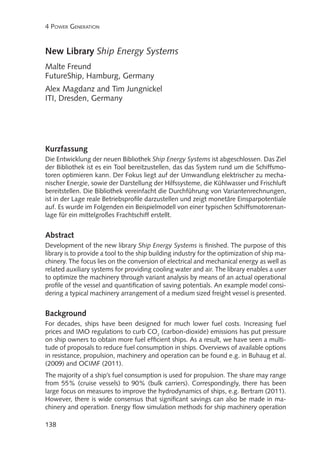
Oil Price 1997 - 2012
140
700
120
600
100
500
80
400
60
300
40
200
20
US $ per Barrel Crude Oil
800
100
US $ per Metric Ton HFO
160
0
0
01/2012
01/2011
01/2010
01/2009
01/2008
01/2007
01/2006
01/2005
01/2004
01/2003
01/2002
01/2001
01/2000
01/1999
01/1998
01/1997
Figure 1: Crude oil prices (continuous line, left axis) and fuel oil prices (dots, right axis)
from 1997 to 2013
Library
Optimization of ship energy efficiency for realistic operation profiles is a key topic in
the shipbuilding industry. Until now, there have only been tools for specific, limited
issues in testing and designing the increasingly complex systems on board ships. Only
typical operation points could be calculated, using standard spreadsheet tools. There
was no comprehensive tool for ship energy management.
Together with ITI, FutureShip has developed a simulation library for designing and
testing the energy efficiency of a ship using the software SimulationX. This library,
called Ship Energy Systems, advances the state of the art in ship energy calculations
significantly:
•• all auxiliary systems of a ship can be modeled and calculated simultaneously,
•• the entire dynamic operation profile of the ship can be entered including ambient air pressure and temperature, seawater temperature, and individual operation profiles of each engine.
Ship Energy Systems facilitates obtaining results from variant calculations, making the
library ideal for design offices and shipyards. In addition, component suppliers may
use the library to provide evidence and supporting documents of the functionality and
energy savings of their components.
139
3. 4 Power Generation
Library Scope
The library was developed to include the main components of a vessels’ machinery, with focus on cooling,
conversion of mechanical and electrical energy and related auxiliary systems. These are the largest consumers
on board. Most components were parameterized with
characteristic curves and a physical description of the
component behavior. The intent was to create models
with data available to the user, not proprietary design
parameters.
A simulation model shall calculate the required energy
supply for given demand characteristics. The operation profiles of engines and electrical consumers are the
starting points of the calculation. In each component of
the modeled system, the losses resulting from energy
transfer or conversion are considered. The end result
is a fuel consumption rate and total fuel consumption
which can be viewed in terms of volume or cost.
Components
Engines are central components to the Ship Energy
Systems library. The engines are modeled from an energy-based, not a mechanical point of view. Based on
the requested mechanical power, the heat flow to the
cooling system and engine room is defined via curves.
The following properties are calculated for the engine:
••
••
••
••
Heat transfer to engine room
Heat transfer to cooling water
Exhaust gas properties
Fuel consumption
The engine cooling circuits can be modeled using components such as pumps, heat exchangers, throttles, fluid
volumes, pressure vessels, and three-way valves. Fluid
data for both water and seawater is available.
Heat is emitted through convection and radiation from
the engines to the engine room. One or more engine
rooms may be present in a simulation model, and each engine is assigned to a particular room using an identifying number. In turn, each engine room is cooled by a fan.
The electrical power required by the fans can be supplied using the generator model.
Based on the efficiency curve and electrical power demand, the generator calculates
the necessary mechanical power. If the requested electrical power exceeds the capa140
4. New Library Ship Energy Systems
city of one generator, the component power splitter can split the requested electrical
power to various other power sources.
The fuel tank component calculates fuel costs resulting from fuel consumption in
order to analyze possible savings made by improved system design or operation. The
fuel costs may be used to calculate payback time or return on investment for system
variations.
Variant Analysis
In a simulation, operating conditions and profiles for engines and electrical power
demand can be described using curves and the changing energy demand for system
variations analyzed. The library design aims for minimal effort in calculating variant
analyses of energy efficiency. The SimulationX Variant Wizard allows the user to automate the process of testing system variations by selecting parameters of interest and
setting corresponding ranges via a simple menu. Results from each variation can be
saved and plotted.
Model Extensions
The Ship Energy Systems library comes with a complete set of parameterized components. The hierarchical library allows users to save commonly used parameter sets
for a component for reuse in new models. For instance, if a ship builder uses a particular type of heat exchanger in the cooling circuits, and knows the parameters for
141
5. 4 Power Generation
that component (nominal temperatures, load, etc.), a new heat exchanger model can
be created by making an extension of the original heat exchanger and saving those
parameters as default. The changes can be made using the SimulationX TypeDesigner,
which helps a user to make the changes step by step. Users can simply drag in their
specialized component to a new simulation model, rather than parameterizing the
original component each time.
Example Model
A simplified engine room is modeled. The model represents a typical configuration of
a medium-size freight vessel with a two-stroke main engine and three auxiliary for
electrical power. The auxiliary systems are implemented with the fresh-water cooling
circuit for the engines and the seawater cooling circuit, which cools the fresh-water
circuit in the central cooler. Additionally, the heat influx into the engine room is modeled by a fan providing cooling air from the environment.
Figure 2: Example model of a medium-size freight vessel
Fig. 2 gives an overview of the example model. Its parts are described below. In Fig. 2,
the main engine is located on the bottom right and the auxiliary engines and generators to its left. The fresh-water cooling circuit surrounds the engines, with the central
cooler and the pump close to the generators. Throttles are used for controlling the
cooling water flow in the different branches of the cooling water system. The seawater cooling circuit is connected to the central cooler on the bottom left of Fig. 2; the
engine room with its fan for cooling air can be found in the upper left. In the upper
142
6. New Library Ship Energy Systems
middle, the icons specifying the boundary conditions for the exhaust gas flow and the
ambient conditions of the environment are located.
Instead of a conventional by-pass control in the
fresh-water cooling circuit, a frequency controlled
seawater cooling pump is demonstrated to keep
the feed water temperature at the desired temperature of 36 °C. This significantly reduces the
amount of seawater pumped through the central
cooler and thus the electrical power demand if the
vessel’s main and auxiliary engines are operated
with lower than design power or at non-tropical
seawater temperatures. This is demonstrated in
Fig. 4 for an exemplary voyage over 18 h. Here,
the main engine load varies between 0% and
Figure 3: Seawater cooling system 95% MCR and seawater temperature between
with frequency control
25 °C and 30 °C. Instead of its nominal rotational speed, the pump is operated between 30% and 80% of the nominal speed. The
varying pump speed is displayed in Fig. 4 (mid, swPump1.n) together with the main
influence factors (main engine operation, seawater temperature, resulting temperature in the fresh-water cooling circuit).
Figure 4: Operational profile of main engine (top), rotational speed of seawater cooling
pump and resulting temperature in fresh-water cooling circuit (middle) and seawater
temperature over the exemplary 18 h voyage
143
7. 4 Power Generation
The electrical power demand is
simulated using the demand from
constant consumers (provided by
ramp signals), in addition to the
power demand from the engine
room fan. The resulting power
demand is distributed to the generators by the power splitter, i.e.
only the necessary generator sets
are running to cover the power
demand.
Figure 5: Power distribution to generators and
attached auxiliary engines
The heat from the individual engines and generators of the model is summed up and connected
to the engine room component
automatically. Cooling air is provided to the engine room by a
speed controlled fan. The used
air is specified by boundary conditions connected to the ambient
conditions and then discharged
back to the environment. The
Figure 6: Engine room compartment with controlled control for the required amount
of cooling air is based on the
cooling air fan and ambient conditions
temperature of the outflowing air
as measured by the temperature
sensor.
The example model integrates key aspects for machinery analysis on a typical layout
of a medium-size freight vessel. Variations in machinery can easily be integrated to
quantify their operational performance and influence on the energy demand.
Conclusion
The new library Ship Energy Systems is developed for simulation of ship machinery with the focus on electrical and mechanical energy conversion and the auxiliary
systems. Aim is to enable the users to easily establish a simulation of the ship machinery, incorporating the operational profile of vessel and individual machinery. Variant
calculations for optimal configuration of machinery can be executed and saving potentials quantified.
Compared to the development of simulation models for each project, the library reduces the required time for simulation of typical ship machinery significantly. The
development effort lies then in the establishing of a model by drag and drop of the
144
8. New Library Ship Energy Systems
components, their logical connection and their adaptation to the present project by
parameterization, not in the challenge of the physical description of the required machinery. The users can integrate their adapted and pre-parameterized components in
the library for a quick reuse in other models as well as integrate special components
which are in the focus of their projects.
References
[1]
BERTRAM, V. (2011), Practical Ship Hydrodynamics, 2nd Ed., Butterworth &
Heinemann, Oxford
[2]
BUHAUG, Ø.; CORBETT, J.J.; ENDRESEN, Ø.; EYRING, V.; FABER, J.;
HANAYAMA, S.; LEE, D.S.; LEE, D.; LINDSTAD, H.; MARKOWSKA, A.Z.;
MJELDE, A.; NELISSEN, D.; NILSEN, J.; PÅLSSON, C.; WINEBRAKE, J.J.; WU,
W.Q.; YOSHIDA, K. (2009), Second IMO GHG study 2009, International
Maritime Organization (IMO), London
[3]
http://www.imo.org/blast/blastDataHelper.asp?data_id=27795&filename=GHGStudyFINAL.pdf
[4]
CORADDU, A.; FIGARI, M.; SAVIO, S. (2013), Ship energy assessment by
numerical simulation, 5th Int. Conf. Computational Methods in Marine Engineering (MARINE), Hamburg, pp.530-540
[5]
DIMOPOULOS, G.G.; KAKALIS, N.M.P. (2010), An integrated modelling
framework for the design, operation and control of marine energy systems,
26th CIMAC World Congress, Bergen
[6]
FREUND, M.; WÜRSIG, G.M.; KABELAC, S. (2009), Simulation tool to evaluate fuel and energy consumption, 8th Conf. Computer and IT Applications in
the Maritime Industries (COMPIT), Budapest, pp.364-373
[7]
HANSEN, H.; FREUND, M. (2010), Assistance tools for operational fuel efficiency, 9th Conf. Computer and IT Applications in the Maritime Industries
(COMPIT), Gubbio, pp.356-366
[8]
OCIMF (2011), GHG emission-mitigating measures for oil tankers – Part A:
Review of reduction potential, Oil Companies International Marine Forum,
London. http://www.ocimf.com/library/information-papers
[9]
VUGT, J. van; MARLEN, B. van (2010), The use of a generic energy systems
(GES) model for fishing vessels, 1st Int. Symp. Fishing Vessel Energy Efficiency
(E-Fishing), Vigo
145