
Recommandé
Contenu connexe
Tendances
Tendances (20)
Similaire à Normal ecg interpretation
Similaire à Normal ecg interpretation (20)
Plus de Subhashini N
Dernier
Dernier (20)
Normal ecg interpretation
- 3. INTRODUCTION • The electrocardiogram (ECG) is one of the simplest and oldest cardiac investigations available, yet it can provide a wealth of useful information and remains an essential part of the assessment of cardiac patients. • With modern machines, surface ECGs are quick and easy to obtain at the bedside and are based on relatively simple electrophysiological concepts.
- 4. What is an ECG? An ECG is simply a representation of the electrical activity of the heart muscle as it changes with time, usually printed on paper for easier analysis. Like other muscles, cardiac muscle contracts in response to electrical depolarization of the muscle cells. It is the sum of this electrical activity, when amplified and recorded for just a few seconds that we know as an ECG.
- 5. Recording the EKG Basics: • ECG graph: 1 mm small squares 5 mm large squares • Paper speed 25 mm/sec standard
- 6. The vertical lines measure amplitude or voltage Each small box represents 0.1 Mv Each large block (made up of 5 small boxes) represents 0.5 mV The horizontal lines measure time Each small box equals 0.04 seconds 2. Each large block (made up of 5 small boxes) equals 0.2 seconds (multiply 0.04 x 5 = 0.2)
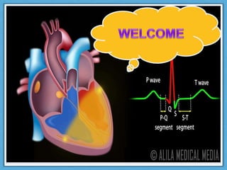
- 9. Major waves of a single normal ECG pattern • P wave: Represents Atrial depolarization, initiated by the SA node. Characteristics: 1.width <3 small squares (0.12 sec) and height <2.5 mm 2.Upward in leads I,II and inverted in lead aVR. This is called sinus’ P’ wave. 3.P wave after the QRS Complex(Retrograde P wave) or inverted P wave indicates its origin from other source.
- 12. QRS complex It Represents ventricle depolarization This also happens to coincide with the part of the cardiac cycle when the myocardial cells in the atria are repolarizing. The impulse is slightly delayed at the AV node before entering the ventricles through the Common AV Bundle.
- 13. Characteristics • Completely negative in lead aVR, maximum positivity in lead II • Normal duration between 0.08 and 0.10 sec, not more than 0.12 sec. • Physiological Q wave not >0.03 sec. • In a right ventricular lead (V1) the S wave is greater than the R wave the height of the R wave in the left ventricular leads (V5, V6) is less than 25 mm
- 14. Normal QRS V1 V6
- 16. J-point Is the end of the QRS complex and the beginning of the ST segment.
- 17. Normal T wave • It Represents Re polarization of ventricles. • Same direction as the preceding QRS complex • Height <5mm in limb leads and <10 mm in precordial leads • Smooth contours • May be tall in athletes
- 18. The normal U Wave It represents re polarization of purkinje fibers and/or the ventricular septum. The most neglected of the ECG waveforms • U wave amplitude is usually < 1/3 T wave amplitude in same lead. • U wave direction is the same as T wave direction in that lead. • U waves are more prominent at slow heart rates and usually best seen in the right precordial leads.
- 19. Intervals and segments PR Interval: From the start of the P wave to the start of the QRS complex PR Segment :From the end of the P wave to the start of the QRS complex J Point:The junction between the QRS complex and the ST segment QT Interval: From the start of the QRS complex to the end of the T wave QRS Interval: From the start to the end of the QRS complex ST Segment: From the end of the QRS complex (J point) to the start of the T wave
- 21. Normal intervals • PR interval: (measured from the beginning of the P wave to the first deflection of the QRS complex). Normally lasts 0.12 and 0.20 seconds. (3 – 5 small squares on ECG paper). • QRS Interval: (measured from first deflection of QRS complex to end of QRS complex at isoelectric line). Interval usually lasts between 0.08 and 0.12 seconds. (3 small squares on ECG paper).
- 23. R-R interval - The RR interval represents the amount of time between heart beats. Thus, the RR interval is heart rate dependent. In fact, most of our methods for determining heart rate from the EKG are dependent on measuring the RR interval. For example if there is 0.6 seconds between beats, and there are 60 seconds per minute, then the heart rate would be 100 beats per minute [(60 sec/minute / (0.6 sec/beat)].
- 24. • QT interval (measured from first deflection of QRS complex to end of T wave at isoelectric line). it is usually about 0.35 seconds in duration, but the duration of the QT interval is very heart rate dependent. • ST segment - Is the segment between the J point (the end of the QRS complex) and the beginning of the T wave.
- 25. ECG Interpretation What is your approach to reading an ECG? •Rate •Rhythm •Axis •Wave morphology •Intervals and •Segment analysis
- 27. The rule of 300 No of big boxes Rate (apprx) 1 300 2 150 3 100 4 75 5 60 6 50
- 28. 10 second rule • As most ECG record 10 seconds of rhythm per page, one can simply count the number of beats present on the ECG and multiply by 6 to get the number of beats per seconds. • Rate: (Number of waves in 10 second strips)x6 • This method works well for irregular rhythm
- 29. Count QRS in 10 second rhythm strip x 6 use this method to determine rate when rhythm is irregular (e.g., atrial fibrillation)
- 30. Rhythm Look at the rhythm strip below and answer the questions • Are P waves present? • yes • Is there a P wave before every QRS complex and a QRS complex after every P wave? • yes • Are the P waves and QRS complexes regular? • yes • Is the PR interval constant? • yes Yes to all these questions, so this is normal sinus rhythm!
- 31. Normal Sinus Rhythm ECG rhythm characterized by a usual rate of anywhere between 60 and 100 beats per min. Every P wave must be followed by a QRS And every QRS is preceded by P wave. Normal duration of PR interval is 3-5 small squares • The P wave is upright in leads I and II.
- 32. Axis Axis is the general flow of electricity as it passes through the heart The QRS axis represents the net overall direction of the heart’s electrical activity.
- 33. Determining the Axis • The quadrant approach • The equiphasic approach
- 35. The Quadrant Approach • Examine the QRS complex in Leads I and aVF to determine if they are predominantly positive or predominantly negative. • The combination should place the axis into one of the 4 quadrants below. I AVF Axis + + Normal + - LAD - + RAD
- 38. • To determine cardiac axis look at QRS complexes of lead II ,III. AXIS LEAD II LEADIII Normal Positive Positive/negativ e Right axis deviation Positive Positive Left axis deviation Negative Negative
- 39. Normal R Wave Progression Transition Zone?
- 40. Transition Zone
- 41. Early & Delayed Transition • Figure 4-7 V1 V2 V3 V4 V5 V6
- 42. PRACTICE
- 43. No. Although there are P waves, they are negative. negative P waves indicate a retrograde conduction likely coming from the AV junction.
- 44. Normal ECG
- 45. CONCLUSION ECG NORMAL VALUES: Heart rate 60 - 100 bpm PR interval 0.12 - 0.20 s QRS interval ≤ 0.12 s QT interval < half RR interval (males < 0.40 s; females < 0.44 s) . P wave amplitude (in lead II) ≤ 3 mV (mm) P wave terminal negative deflection (in lead V1) ≤ 1 mV (mm)Q wave < 0.04 s (1 mm) and < 1/3 of R wave amplitude in the same lead.
Notes de l'éditeur
- SLIDE STARTS WITH QUESTION ONLY Ask interns about their method for interpreting an ECG. Emphasize the importance of interpreting an ECG always in the same order so that nothing is missed. Question will appear first in presentation, then answers.
- Rate — Ask interns to define normal rate, bradycardia and tachycardia. Square counting: 300-150-100-75-60-42 or count number of QRS complexes in rhythm strip and multiply by 6 (especially for atrial fibrillation).
- 1st Example: Normal sinus rhythm 2nd Example: Third degree heart block No P waves – atrial fibrillation
- Left Axis Deviation (LAD) Right Axis Deviation (RAD) The cardiac axis refers to the mean direction of the wave of ventricular depolarization in the frontal plane, measured from a zero reference point. Normal is anywhere from -30 degrees to +90 degrees