Architecture Documentation Views
•Télécharger en tant que DOCX, PDF•
3 j'aime•2,365 vues


Recommandé
Contenu connexe
Tendances
Tendances (20)
En vedette
En vedette (20)
Similaire à Architecture Documentation Views
Similaire à Architecture Documentation Views (20)
Plus de Sudarshan Dhondaley
Dernier
Dernier (20)
Architecture Documentation Views
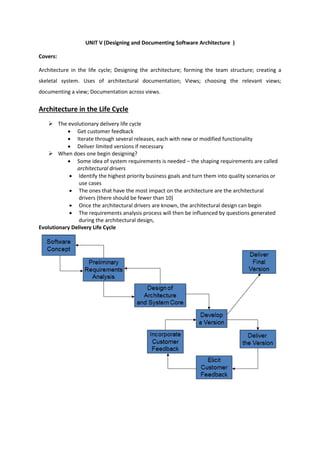
- 1. UNIT V (Designing and Documenting Software Architecture ) Covers: Architecture in the life cycle; Designing the architecture; forming the team structure; creating a skeletal system. Uses of architectural documentation; Views; choosing the relevant views; documenting a view; Documentation across views. Architecture in the Life Cycle The evolutionary delivery life cycle Get customer feedback Iterate through several releases, each with new or modified functionality Deliver limited versions if necessary When does one begin designing? Some idea of system requirements is needed – the shaping requirements are called architectural drivers Identify the highest priority business goals and turn them into quality scenarios or use cases The ones that have the most impact on the architecture are the architectural drivers (there should be fewer than 10) Once the architectural drivers are known, the architectural design can begin The requirements analysis process will then be influenced by questions generated during the architectural design, Evolutionary Delivery Life Cycle
- 2. Designing the Architecture • A method called Attribute Driven Design (ADD) can be used to design an architecture to satisfy both quality and functional requirements. • ADD can be viewed as an extension to other developments methods, such as the Rational Unified Process (RUP). Attribute-Driven Design • ADD bases the decomposition process on the quality attributes the software has to fulfill. • It is a recursive decomposition process, where, at each stage, tactics and architectural patterns are chosen to satisfy a set of quality scenarios and then functionality is allocated to instantiate the module types provided by the pattern. • The system is described as a set of containers for functionality and the interactions among them. • This is a coarse grained framework for achieving the functionality. Example Application of ADD • Sample problem: A garage door opener within a home information system. The system is responsible for raising and lowering the door via a switch, remote control, or the home information system. It is also possible to diagnose problems with the opener from within the home information system. Input to ADD • A set of requirements (typically expressed as use cases) and constraints • A set of quality requirements expressed as system-specific quality scenarios including, in this case: – The device and controls for opening and closing the door are different for the various products in the product line. They may include controls from within a home information system – The processor used in different products will differ. – If an obstacle (person or object) is detected by the garage door during descent, it must halt (alternately re-open) within 0.1 second. The garage door opener should be accessible for diagnosis and administration from within the home information system using a product-specific diagnosis protocol. (Continued .. lol Skipped) ADD Steps: 1. Choose the module to decompose – the module to start with is usually the whole system. 2. Refine the module according to the following steps: a. Choose the architectural drivers from the set of concrete quality scenarios and functional requirements. b. Choose an architectural pattern that satisfies the architectural drivers based on the tactics that can be used to achieve the drivers. c. Instantiate modules and allocate functionality from the use cases and represent using multiple views. d. Define interfaces of the child modules. The decomposition provides modules and constraints on the types of module interactions. Document this information in the interface document for each module. e. Verify and refine use cases and quality scenarios and make them constraints for child modules. 3. Repeat the steps above for every module that needs further decomposition.
- 3. Forming the Team Structure • Once the first few levels of the architecture’s module decomposition structure are fairly stable, those modules can be allocated to development teams. • Within teams there needs to be high-bandwidth communications. Between teams, low-bandwidth communications are sufficient (and in fact crucial). • If interactions between the teams is complex, either: – The interactions among the elements they are creating are needlessly complex – Or, the requirements for those elements were not sufficiently “hardened” before development commenced • Like software systems, teams should strive for high cohesion(forming a united whole) and low coupling (the pairing of two items). • Each module of the system constitutes its own small domain (area of specialized knowledge or expertise). • This makes for a natural fit between teams and modules of the decomposition structure. • The effective use of staff, therefore, is to assign members to a team based on their expertise. • The organizational structure also affects the architecture. • Organizational entities formed for one project are motivated to preserve their existence and will want to maximize their importance in new projects. Creating a Skeletal System • Once an architecture is sufficiently designed and teams are in place to build it, a skeletal system can be constructed. • The architecture provides a guide as to the order in which portions of the system should be implemented. – First implement the software that deals with the execution and interaction of architectural components. – Add some simple functions. • The result is a running system onto which useful functionality can be added • To lower risk the most problematic functions should be added first. • Then the functionality needed to support those problematic functions is added. • This process is continued, growing larger and larger increments of the system until it is complete.
- 4. Architecture Documentation • Even the best architecture will be useless if the people who need it – do not know what it is; – cannot understand it well enough to use, build, or modify it; – misunderstand it and apply it incorrectly. • All of the effort, analysis, hard work, and insightful design on the part of the architecture team will have been wasted. Uses of architectural documentation • Architecture documentation must – be sufficiently transparent and accessible to be quickly understood by new employees – be sufficiently concrete to serve as a blueprint for construction – have enough information to serve as a basis for analysis. • Architecture documentation is both prescriptive and descriptive. – For some audiences, it prescribes what should be true, placing constraints on decisions yet to be made. – For other audiences, it describes what is true, recounting decisions already made about a system’s design. • Understanding stakeholder uses of architecture documentation is essential • Those uses determine the information to capture. Three Uses for Architecture Documentation 1. Education • Introducing people to the system – New members of the team – External analysts or evaluators – New architect 2. Primary vehicle for communication among stakeholders • Especially architect to developers • Especially architect to future architect! 3. Basis for system analysis and construction • Architecture tells implementers what to implement. • Each module has interfaces that must be provided and uses interfaces from other modules. • Documentation can serve as a receptacle for registering and communicating unresolved issues. Architecture documentation serves as the basis for architecture evaluation.
- 5. Views • Views let us divide a software architecture into a number of (we hope) interesting and manageable representations of the system. • Principle of architecture documentation: – Documenting an architecture is a matter of documenting the relevant views and then adding documentation that applies to more than one view. Which Views? The Ones You Need! • Different views support different goals and uses. • We do not advocate a particular view or collection of views. • The views you should document depend on the uses you expect to make of the documentation. Each view has a cost and a benefit; you should ensure that the benefits of maintaining a view outweigh its costs. Choosing the relevant Views You can determine which views are required, when to create them, and how much detail to include if you know the following: – What people, and with what skills, are available – Which standards you have to comply with – What budget is on hand – What the schedule is – What the information needs of the important stakeholders are – What the driving quality attribute requirements are – What the approximate size of the system is At a minimum, expect to have at least one module view, at least one C&C view, and for larger systems, at least one allocation view in your architecture document Documenting a View • Section 1: The Primary Presentation. – The primary presentation shows the elements and relations of the view. – The primary presentation should contain the information you wish to convey about the system—in the vocabulary of that view. – The primary presentation is most often graphical. • It might be a diagram you’ve drawn in an informal notation using a simple drawing tool, or it might be a diagram in a semiformal or formal notation imported from a design or modeling tool that you’re using. • If your primary presentation is graphical, make sure to include a key that explains the notation. • Lack of a key is the most common mistake that we see in documentation in practice. – Occasionally the primary presentation will be textual, such as a table or a list. • If that text is presented according to certain stylistic rules, these rules should be stated or incorporated by reference, as the analog to the graphical notation key. • Section 2: The Element Catalog. – The element catalog details at least those elements depicted in the primary presentation. • For instance, if a diagram shows elements A, B, and C, then the element catalog needs to explain what A, B, and C are.
- 6. • If elements or relations relevant to this view were omitted from the primary presentation, they should be introduced and explained in the catalog. – Parts of the catalog: • Elements and their properties. This section names each element in the view and lists the properties of that element. Each view introduced in Chapter 1 listed a set of suggested properties associated with that view. • Relations and their properties. Each view has specific relation types that it depicts among the elements in that view. • Element interfaces. This section documents element interfaces. Element behavior. This section documents element behavior that is not obvious from the primary presentation • Section 3: Context Diagram. – A context diagram shows how the system or portion of the system depicted in this view relates to its environment. – The purpose of a context diagram is to depict the scope of a view. – Entities in the environment may be humans, other computer systems, or physical objects, such as sensors or controlled devices. • Section 4: Variability Guide. – A variability guide shows how to exercise any variation points that are a part of the architecture shown in this view. • Section 5: Rationale. – Rationale explains why the design reflected in the view came to be. – The goal of this section is to explain why the design is as it is and to provide a convincing argument that it is sound. – The choice of a pattern in this view should be justified here by describing the architectural problem that the chosen pattern solves and the rationale for choosing it over another. View Template
- 7. Documentation Across Views Cross-view documentation consists of just three major aspects, which we can summarize as how- what-why Summary of cross-view documentation How the documentation is organized to a stakeholder: Every suite of architectural documentation needs an introductory piece to explain its organization to a novice stakeholder and to help that stakeholder access the information he or she is most interested in. There are two kinds of "how" information: View Catalog A view catalog is the reader's introduction to the views that the architect has chosen to include in the suite of documentation. There is one entry in the view catalog for each view given in the documentation suite. Each entry should give the following: – The name of the view and what style it instantiates – A description of the view's element types, relation types, and properties – A description of what the view is for – Management information about the view document, such as the latest version, the location of the view document, and the owner of the view document View Template A view template is the standard organization for a view. It helps a reader navigate quickly to a section of interest, and it helps a writer organize the information and establish criteria for knowing how much work is left to do. What the architecture is: This section provides information about the system whose architecture is being documented, the relation of the views to each other, and an index of architectural elements. System Overview This is a short prose description of what the system's function is, who its users are, and any important background or constraints. The intent is to provide readers with a consistent mental model of the system and its purpose. Sometimes the project at large will have a system overview, in which case this section of the architectural documentation simply points to that. Mapping between Views Since all of the views of an architecture describe the same system, it stands to reason that any two views will have much in common. Helping a reader of the documentation understand the relationships among views will give him a powerful insight into how the architecture works as a
- 8. unified conceptual whole. Being clear about the relationship by providing mappings between views is the key to increased understanding and decreased confusion. Element List The element list is simply an index of all of the elements that appear in any of the views, along with a pointer to where each one is defined. This will help stakeholders look up items of interest quickly. Project Glossary The glossary lists and defines terms unique to the system that have special meaning. A list of acronyms, and the meaning of each, will also be appreciated by stakeholders. If an appropriate glossary already exists, a pointer to it will suffice here. Why the architecture is the way it is: Rationale Cross-view rationale explains how the overall architecture is in fact a solution to its requirements. One might use the rationale to explain: – The implications of system-wide design choices on meeting the requirements or satisfying constraints. – The effect on the architecture when adding a foreseen new requirement or changing an existing one. – The constraints on the developer in implementing a solution. – Decision alternatives that were rejected. In general, the rationale explains why a decision was made and what the implications are in changing it.