
Recommandé
Contenu connexe
Tendances
Tendances (20)
En vedette
En vedette (20)
Similaire à Heat transfer in thermal engineering
Similaire à Heat transfer in thermal engineering (20)
Plus de Ashish Khudaiwala
Dernier
Dernier (20)
Heat transfer in thermal engineering
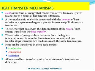
- 1. HEAT TRANSFER MECHANISMS Heat as the form of energy that can be transferred from one system to another as a result of temperature difference. A thermodynamic analysis is concerned with the amount of heat transfer as a system undergoes a process from one equilibrium state to another. The science that deals with the determination of the rates of such energy transfers is the heat transfer. The transfer of energy as heat is always from the higher- temperature medium to the lower-temperature one, and heat transfer stops when the two mediums reach the same temperature. Heat can be transferred in three basic modes: conduction convection radiation All modes of heat transfer require the existence of a temperature difference. A.N.KHUDAIWALA (L.M.E) G.P.PORBANDAR
- 2. Heat conduction through a large plane wall of thickness ∆x and area A. CONDUCTION Conduction: The transfer of energy from the more energetic particles of a substance to the adjacent less energetic ones as a result of interactions between the particles. In gases and liquids, conduction is due to the collisions and diffusion of the molecules during their random motion. In solids, it is due to the combination of vibrations of the molecules in a lattice and the energy transport by free electrons. The rate of heat conduction through a plane layer is proportional to the temperature difference across the layer and the heat transfer area, but is inversely proportional to the thickness of the layer. A.N.KHUDAIWALA (L.M.E) G.P.PORBANDAR
- 3. When x → 0 Fourier’s law of heat conduction Thermal conductivity, k: A measure of the ability of a material to conduct heat. Temperature gradient dT/dx: The slope of the temperature curve on a T-x diagram. Heat is conducted in the direction of decreasing temperature, and the temperature gradient becomes negative when temperature decreases with increasing x. The negative sign in the equation ensures that heat transfer in the positive x direction is a positive quantity. The rate of heat conduction through a solid is directly proportional to its thermal conductivity. In heat conduction analysis, A represents the area normal to the direction of heat transfer.A.N.KHUDAIWALA (L.M.E) G.P.PORBANDAR
- 4. Thermal Conductivity Thermal conductivity: The rate of heat transfer through a unit thickness of the material per unit area per unit temperature difference. The thermal conductivity of a material is a measure of the ability of the material to conduct heat. A high value for thermal conductivity indicates that the material is a good heat conductor, and a low value indicates that the material is a poor heat conductor or insulator. A simple experimental setup to determine the thermal conductivity of a material. A.N.KHUDAIWALA (L.M.E) G.P.PORBANDAR
- 5. The range of thermal conductivity of various materials at room temperature. A.N.KHUDAIWALA (L.M.E) G.P.PORBANDAR
- 6. The mechanisms of heat conduction in different phases of a substance. The thermal conductivities of gases such as air vary by a factor of 104 from those of pure metals such as copper. Pure crystals and metals have the highest thermal conductivities, and gases and insulating materials the lowest. A.N.KHUDAIWALA (L.M.E) G.P.PORBANDAR
- 7. The variation of the thermal conductivity of various solids, liquids, and gases with temperature. A.N.KHUDAIWALA (L.M.E) G.P.PORBANDAR
- 8. Thermal Diffusivity cp Specific heat, J/kg · °C: Heat capacity per unit mass ρcp Heat capacity, J/m3 ·°C: Heat capacity per unit volume α Thermal diffusivity, m2 /s: Represents how fast heat diffuses through a material A material that has a high thermal conductivity or a low heat capacity will obviously have a large thermal diffusivity. The larger the thermal diffusivity, the faster the propagation of heat into the medium. A small value of thermal diffusivity means that heat is mostly absorbed by the material and a small amount of heat is conducted further. A.N.KHUDAIWALA (L.M.E) G.P.PORBANDAR
- 9. CONVECTION Convection: The mode of energy transfer between a solid surface and the adjacent liquid or gas that is in motion, and it involves the combined effects of conduction and fluid motion. The faster the fluid motion, the greater the convection heat transfer. In the absence of any bulk fluid motion, heat transfer between a solid surface and the adjacent fluid is by pure conduction. Heat transfer from a hot surface to air by convection. A.N.KHUDAIWALA (L.M.E) G.P.PORBANDAR
- 10. Forced convection: If the fluid is forced to flow over the surface by external means such as a fan, pump, or the wind. Natural (or free) convection: If the fluid motion is caused by buoyancy forces that are induced by density differences due to the variation of temperature in the fluid. The cooling of a boiled egg by forced and natural convection. Heat transfer processes that involve change of phase of a fluid are also considered to be convection because of the fluid motion induced during the process, such as the rise of the vapor bubbles during boiling or the fall of the liquid droplets during condensation. A.N.KHUDAIWALA (L.M.E) G.P.PORBANDAR
- 11. Newton’s law of cooling h convection heat transfer coefficient, W/m2 · °C As the surface area through which convection heat transfer takes place Ts the surface temperature T∞ the temperature of the fluid sufficiently far from the surface. The convection heat transfer coefficient h is not a property of the fluid. It is an experimentally determined parameter whose value depends on all the variables influencing convection such as - the surface geometry - the nature of fluid motion - the properties of the fluid - the bulk fluid velocity A.N.KHUDAIWALA (L.M.E) G.P.PORBANDAR
- 12. RADIATION • Radiation: The energy emitted by matter in the form of electromagnetic waves (or photons) as a result of the changes in the electronic configurations of the atoms or molecules. • Unlike conduction and convection, the transfer of heat by radiation does not require the presence of an intervening medium. • In fact, heat transfer by radiation is fastest (at the speed of light) and it suffers no attenuation in a vacuum. This is how the energy of the sun reaches the earth. • In heat transfer studies we are interested in thermal radiation, which is the form of radiation emitted by bodies because of their temperature. • All bodies at a temperature above absolute zero emit thermal radiation. • Radiation is a volumetric phenomenon, and all solids, liquids, and gases emit, absorb, or transmit radiation to varying degrees. • However, radiation is usually considered to be a surface phenomenon for solids. A.N.KHUDAIWALA (L.M.E) G.P.PORBANDAR
- 13. Stefan–Boltzmann law σ = 5.670 × 10⁻⁸ W/m2 · K4 Stefan–Boltzmann constant Blackbody: The idealized surface that emits radiation at the maximum rate. Blackbody radiation represents the maximum amount of radiation that can be emitted from a surface at a specified temperature. Emissivity ε : A measure of how closely a surface approximates a blackbody for which ε = 1 of the surface. 0≤ ε ≤ 1. Radiation emitted by real surfaces A.N.KHUDAIWALA (L.M.E) G.P.PORBANDAR
- 14. Absorptivity α: The fraction of the radiation energy incident on a surface that is absorbed by the surface. 0≤ α ≤ 1 A blackbody absorbs the entire radiation incident on it (α = 1). Kirchhoff’s law: The emissivity and the absorptivity of a surface at a given temperature and wavelength are equal. The absorption of radiation incident on an opaque surface of absorptivity . A.N.KHUDAIWALA (L.M.E) G.P.PORBANDAR
- 15. Radiation heat transfer between a surface and the surfaces surrounding it. Net radiation heat transfer: The difference between the rates of radiation emitted by the surface and the radiation absorbed. The determination of the net rate of heat transfer by radiation between two surfaces is a complicated matter since it depends on • the properties of the surfaces • their orientation relative to each other • the interaction of the medium between the surfaces with radiation Radiation is usually significant relative to conduction or natural convection, but negligible relative to forced convection. When a surface is completely enclosed by a much larger (or black) surface at temperature Tsurr separated by a gas (such as air) that does not intervene with radiation, the net rate of radiation heat transfer between these two surfaces is given by A.N.KHUDAIWALA (L.M.E) G.P.PORBANDAR
- 16. Combined heat transfer coefficient hcombined Includes the effects of both convection and radiation When radiation and convection occur simultaneously between a surface and a gas: A.N.KHUDAIWALA (L.M.E) G.P.PORBANDAR
- 17. INSULATING MATERIALS INSULATING MATERIALS, GENERAL PROPERTIES PHYSICAL PROPERTIES ELECTRIAL PROPERTIES THERMAL PROPERTIES CHEMICAL PROPERTIES MECHANICAL PROPERTIES A.N.KHUDAIWALA (L.M.E) G.P.PORBANDAR
- 18. • INSULATING MATERIALS AND THEIR APPLICATIONS PLASTICS NATURAL INSULATING MATERIALS GASEOUS MATERIALS A.N.KHUDAIWALA (L.M.E) G.P.PORBANDAR
- 19. INTRODUCTION The materials which have very high resistivity i.e. offers a very high resistance to the flow of electric current. Insulating materials plays an important part in various electrical and electronic circuits. In domestic wiring insulating material protect us from shock and also prevent leakage current. So insulating material offers a wide range of uses in engineering applications. A.N.KHUDAIWALA (L.M.E) G.P.PORBANDAR
- 20. FACTORS AFFECTING SELECTION OF AN INSULATING MATERIAL 1. Operating condition : Before selecting an insulating material for a particular application the selection should be made on the basis of operating temperature, pressure and magnitude of voltage and current. 2. Easy in shaping : Shape and size is also important affect. 3. Availability of material : The material is easily available. 4. Cost : Cost is also a important factor. A.N.KHUDAIWALA (L.M.E) G.P.PORBANDAR
- 21. CLASSIFICATION OF SUBSTANCES Conductors Insulators Semiconductors A.N.KHUDAIWALA (L.M.E) G.P.PORBANDAR
- 22. CONDUCTORS The substances through which electric current can flow easily are called conductors. e.g. Silver, gold, copper, aluminum etc. Conductors have a large number of free electrons. Generally metals have a large number of free electrons, So all metals are good conductors. A.N.KHUDAIWALA (L.M.E) G.P.PORBANDAR
- 23. INSULATORS Those substances through which electric current cannot pass easily are called insulators. e.g. Glass, Mica, dry Air, Bakelite etc. A.N.KHUDAIWALA (L.M.E) G.P.PORBANDAR
- 24. SEMICONDUCTORS The substances whose resistivity lies between the resistivity of conductors and insulators are called semiconductors. e.g. Germanium, Silicon, Carbon etc. A.N.KHUDAIWALA (L.M.E) G.P.PORBANDAR
- 25. RESISTIVITY Resistivity is the resistance between the two opposite faces of a cube having each side equal to one meter. Resistivity of CONDUCTORS 10-8 to 10-3 ohm-m INSULATORS 1010-20 ohm-m SEMICONDUCTORS 100-0.5 ohm-m A.N.KHUDAIWALA (L.M.E) G.P.PORBANDAR
- 26. HEAT EXCHANGERS • Recognize numerous types of heat exchangers, and classify them • Develop an awareness of fouling on surfaces, and determine the overall heat transfer coefficient for a heat exchanger • Perform a general energy analysis on heat exchangers • Obtain a relation for the logarithmic mean temperature difference for use in the LMTD method, and modify it for different types of heat exchangers using the correction factor • Develop relations for effectiveness, and analyze heat exchangers when outlet temperatures are not known using the effectiveness-NTU method • Know the primary considerations in the selection of heat exchangers. A.N.KHUDAIWALA (L.M.E) G.P.PORBANDAR
- 27. TYPES OF HEAT EXCHANGERS A.N.KHUDAIWALA (L.M.E) G.P.PORBANDAR
- 28. Compact heat exchanger: It has a large heat transfer surface area per unit volume (e.g., car radiator, human lung). A heat exchanger with the area density β > 700 m2 /m3 is classified as being compact. Cross-flow: In compact heat exchangers, the two fluids usually move perpendicular to each other. The cross- flow is further classified as unmixed and mixed flow. A.N.KHUDAIWALA (L.M.E) G.P.PORBANDAR
- 29. Shell-and-tube heat exchanger: The most common type of heat exchanger in industrial applications. They contain a large number of tubes (sometimes several hundred) packed in a shell with their axes parallel to that of the shell. Heat transfer takes place as one fluid flows inside the tubes while the other fluid flows outside the tubes through the shell. Shell-and-tube heat exchangers are further classified according to the number of shell and tube passes involved. A.N.KHUDAIWALA (L.M.E) G.P.PORBANDAR
- 30. Regenerative heat exchanger: Involves the alternate passage of the hot and cold fluid streams through the same flow area. Dynamic-type regenerator: Involves a rotating drum and continuous flow of the hot and cold fluid through different portions of the drum so that any portion of the drum passes periodically through the hot stream, storing heat, and then through the cold stream, rejecting this stored heat. Condenser: One of the fluids is cooled and condenses as it flows through the heat exchanger. Boiler: One of the fluids absorbs heat and vaporizes. A.N.KHUDAIWALA (L.M.E) G.P.PORBANDAR
- 31. Plate and frame (or just plate) heat exchanger: Consists of a series of plates with corrugated flat flow passages. The hot and cold fluids flow in alternate passages, and thus each cold fluid stream is surrounded by two hot fluid streams, resulting in very effective heat transfer. Well suited for liquid-to-liquid applications. A plate-and-frame liquid-to-liquid heat exchanger. A.N.KHUDAIWALA (L.M.E) G.P.PORBANDAR
- 32. THE OVERALL HEAT TRANSFER COEFFICIENT • A heat exchanger typically involves two flowing fluids separated by a solid wall. • Heat is first transferred from the hot fluid to the wall by convection, through the wall by conduction, and from the wall to the cold fluid again by convection. • Any radiation effects are usually included in the convection heat transfer coefficients. Thermal resistance network associated with heat transfer in a double-pipe heat exchanger.A.N.KHUDAIWALA (L.M.E) G.P.PORBANDAR
- 33. U the overall heat transfer coefficient, W/m2 ⋅°C When The overall heat transfer coefficient U is dominated by the smaller convection coefficient. When one of the convection coefficients is much smaller than the other (say, hi << ho), we have 1/hi >> 1/ho, and thus U ≈ hi. This situation arises frequently when one of the fluids is a gas and the other is a liquid. In such cases, fins are commonly used on the gas side to enhance the product UA and thus the heat transfer on that side. A.N.KHUDAIWALA (L.M.E) G.P.PORBANDAR
- 34. The overall heat transfer coefficient ranges from about 10 W/m2 ⋅°C for gas-to-gas heat exchangers to about 10,000 W/m2 ⋅°C for heat exchangers that involve phase changes. For short fins of high thermal conductivity, we can use this total area in the convection resistance relation Rconv = 1/hAs To account for fin efficiency When the tube is finned on one side to enhance heat transfer, the total heat transfer surface area on the finned side is A.N.KHUDAIWALA (L.M.E) G.P.PORBANDAR
- 35. Fouling Factor The performance of heat exchangers usually deteriorates with time as a result of accumulation of deposits on heat transfer surfaces. The layer of deposits represents additional resistance to heat transfer. This is represented by a fouling factor Rf. The fouling factor increases with the operating temperature and the length of service and decreases with the velocity of the fluids. A.N.KHUDAIWALA (L.M.E) G.P.PORBANDAR
- 36. THE LOG MEAN TEMPERATURE DIFFERENCE METHOD Variation of the fluid temperatures in a parallel-flow double-pipe heat exchanger. log mean temperature difference A.N.KHUDAIWALA (L.M.E) G.P.PORBANDAR
- 37. The arithmetic mean temperature difference The logarithmic mean temperature difference ∆Tlm is an exact representation of the average temperature difference between the hot and cold fluids. Note that ∆Tlm is always less than ∆Tam. Therefore, using ∆Tam in calculations instead of ∆Tlm will overestimate the rate of heat transfer in a heat exchanger between the two fluids. When ∆T1 differs from ∆T2 by no more than 40 percent, the error in using the arithmetic mean temperature difference is less than 1 percent. But the error increases to undesirable levels when ∆T1 differs from ∆T2 by greater amounts. A.N.KHUDAIWALA (L.M.E) G.P.PORBANDAR
- 38. Counter-Flow Heat Exchangers In the limiting case, the cold fluid will be heated to the inlet temperature of the hot fluid. However, the outlet temperature of the cold fluid can never exceed the inlet temperature of the hot fluid. For specified inlet and outlet temperatures, ∆Tlm a counter-flow heat exchanger is always greater than that for a parallel-flow heat exchanger. That is, ∆Tlm, CF > ∆Tlm, PF, and thus a smaller surface area (and thus a smaller heat exchanger) is needed to achieve a specified heat transfer rate in a counter- flow heat exchanger. When the heat capacity rates of the two fluids are equal A.N.KHUDAIWALA (L.M.E) G.P.PORBANDAR
- 39. Multipass and Cross-Flow Heat Exchangers: Use of a Correction Factor F correction factor depends on the geometry of the heat exchanger and the inlet and outlet temperatures of the hot and cold fluid streams. F for common cross-flow and shell-and- tube heat exchanger configurations is given in the figure versus two temperature ratios P and R defined as 1 and 2 inlet and outlet T and t shell- and tube-side temperatures F = 1 for a condenser or boiler A.N.KHUDAIWALA (L.M.E) G.P.PORBANDAR
- 40. Correction factor F charts for common shell- and-tube heat exchangers. A.N.KHUDAIWALA (L.M.E) G.P.PORBANDAR
- 41. Correction factor F charts for common cross-flow heat exchangers. A.N.KHUDAIWALA (L.M.E) G.P.PORBANDAR
- 42. The LMTD method is very suitable for determining the size of a heat exchanger to realize prescribed outlet temperatures when the mass flow rates and the inlet and outlet temperatures of the hot and cold fluids are specified. With the LMTD method, the task is to select a heat exchanger that will meet the prescribed heat transfer requirements. The procedure to be followed by the selection process is: 1. Select the type of heat exchanger suitable for the application. 2. Determine any unknown inlet or outlet temperature and the heat transfer rate using an energy balance. 3. Calculate the log mean temperature difference ∆Tlm and the correction factor F, if necessary. 4. Obtain (select or calculate) the value of the overall heat transfer coefficient U. 5. Calculate the heat transfer surface area As . The task is completed by selecting a heat exchanger that has a heat transfer surface area equal to or larger than As. A.N.KHUDAIWALA (L.M.E) G.P.PORBANDAR
- 43. THE EFFECTIVENESS–NTU METHOD A second kind of problem encountered in heat exchanger analysis is the determination of the heat transfer rate and the outlet temperatures of the hot and cold fluids for prescribed fluid mass flow rates and inlet temperatures when the type and size of the heat exchanger are specified. Heat transfer effectiveness the maximum possible heat transfer rate Cmin is the smaller of Ch and Cc A.N.KHUDAIWALA (L.M.E) G.P.PORBANDAR
- 44. Actual heat transfer rate A.N.KHUDAIWALA (L.M.E) G.P.PORBANDAR
- 45. The effectiveness of a heat exchanger depends on the geometry of the heat exchanger as well as the flow arrangement. Therefore, different types of heat exchangers have different effectiveness relations. We illustrate the development of the effectiveness e relation for the double-pipe parallel-flow heat exchanger. A.N.KHUDAIWALA (L.M.E) G.P.PORBANDAR
- 46. Effectiveness relations of the heat exchangers typically involve the dimensionless group UAs /Cmin. This quantity is called the number of transfer units NTU. For specified values of U and Cmin, the value of NTU is a measure of the surface area As. Thus, the larger the NTU, the larger the heat exchanger. capacity ratio The effectiveness of a heat exchanger is a function of the number of transfer units NTU and the capacity ratio c. A.N.KHUDAIWALA (L.M.E) G.P.PORBANDAR
- 48. Effectiveness for heat exchangers. A.N.KHUDAIWALA (L.M.E) G.P.PORBANDAR
- 50. When all the inlet and outlet temperatures are specified, the size of the heat exchanger can easily be determined using the LMTD method. Alternatively, it can be determined from the effectiveness– NTU method by first evaluating the effectiveness from its definition and then the NTU from the appropriate NTU relation.A.N.KHUDAIWALA (L.M.E) G.P.PORBANDAR
- 51. (e.g., boiler, condenser) A.N.KHUDAIWALA (L.M.E) G.P.PORBANDAR