A transformer is a passive electrical device that transfers electrical energy from one electrical circuit to another, or multiple circuits. A varying current in any one coil of the transformer produces a varying magnetic flux in the transformer's core
Nelamangala Call Girls: 🍓 7737669865 🍓 High Profile Model Escorts | Bangalore...
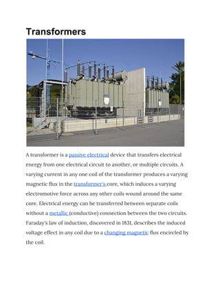
Transformers
1. Transformers
A transformer is a passive electrical device that transfers electrical
energy from one electrical circuit to another, or multiple circuits. A
varying current in any one coil of the transformer produces a varying
magnetic flux in the transformer's core, which induces a varying
electromotive force across any other coils wound around the same
core. Electrical energy can be transferred between separate coils
without a metallic (conductive) connection between the two circuits.
Faraday's law of induction, discovered in 1831, describes the induced
voltage effect in any coil due to a changing magnetic flux encircled by
the coil.
2. Transformers are most commonly used for increasing low AC voltages
at high current (a step-up transformer) or decreasing high AC voltages
at low current (a step-down transformer) in electric power
applications, and for coupling the stages of signal processing circuits.
Transformers can also be used for isolation, where the voltage in equals
the voltage out, with separate coils not electrically bonded to one
another.
AddressBazar.com is an Bangladeshi Online Yellow Page. From here you
will find important and necessary information of various Transformers and
Spares related organizations in Bangladesh.
Since the invention of the first constant-potential transformer in 1885,
transformers have become essential for the transmission, distribution,
and utilization of alternating current electric power. A wide range of
transformer designs is encountered in electronic and electric power
applications. Transformers range in size from RF transformers less than
a cubic centimeter in volume, to units weighing hundreds of tons used
to interconnect the power grid.
Principles
Ideal transformer
An ideal transformer is a theoretical linear transformer that is lossless
and perfectly coupled. Perfect coupling implies infinitely high core
3. magnetic permeability and winding inductances and zero net
magnetomotive force (i.e. ipnp - isns = 0).
A varying current in the transformer's primary winding attempts to
create a varying magnetic flux in the transformer core, which is also
encircled by the secondary winding. This varying flux at the secondary
winding induces a varying electromotive force (EMF, voltage) in the
secondary winding due to electromagnetic induction and the
secondary current produced creates a flux equal and opposite to that
produced by the primary winding, in accordance with Lenz's law.
The windings are wound around a core of infinitely high magnetic
permeability so that all of the magnetic flux passes through both the
4. primary and secondary windings. With a voltage source connected to
the primary winding and a load connected to the secondary winding,
the transformer currents flow in the indicated directions and the core
magnetomotive force cancels to zero.
According to Faraday's law, since the same magnetic flux passes
through both the primary and secondary windings in an ideal
transformer, a voltage is induced in each winding proportional to its
number of windings. The transformer winding voltage ratio is directly
proportional to the winding turns ratio.
The ideal transformer identity shown in eq. 5 is a reasonable
approximation for the typical commercial transformer, with voltage
ratio and winding turns ratio both being inversely proportional to the
corresponding current ratio.
The load impedance referred to the primary circuit is equal to the turns
ratio squared times the secondary circuit load impedance.
Real transformer
Deviations from ideal transformer
The ideal transformer model neglects the following basic linear aspects
of real transformers:
(a) Core losses, collectively called magnetizing current losses,
consisting of
5. ● Hysteresis losses due to nonlinear magnetic effects in the
transformer core, and
● Eddy current losses due to joule heating in the core that are
proportional to the square of the transformer's applied voltage.
(b) Unlike the ideal model, the windings in a real transformer have
non-zero resistances and inductances associated with:
● Joule losses due to resistance in the primary and secondary
windings
● Leakage flux that escapes from the core and passes through
one winding only resulting in primary and secondary reactive
impedance.
(c) similar to an inductor, parasitic capacitance and self-resonance
phenomenon due to the electric field distribution. Three kinds of
6. parasitic capacitance are usually considered and the closed-loop
equations are provided
● Capacitance between adjacent turns in any one layer;
● Capacitance between adjacent layers;
● Capacitance between the core and the layer(s) adjacent to the
core;
Inclusion of capacitance into the transformer model is complicated,
and is rarely attempted; the ‘real’ transformer model’s equivalent circuit
does not include parasitic capacitance. However, the capacitance effect
can be measured by comparing open-circuit inductance, i.e. the
inductance of a primary winding when the secondary circuit is open, to
a short-circuit inductance when the secondary winding is shorted.
Leakage flux
The ideal transformer model assumes that all flux generated by the
primary winding links all the turns of every winding, including itself. In
practice, some flux traverses paths that take it outside the windings.
Such flux is termed leakage flux, and results in leakage inductance in
series with the mutually coupled transformer windings. Leakage flux
results in energy being alternately stored in and discharged from the
magnetic fields with each cycle of the power supply. It is not directly a
power loss, but results in inferior voltage regulation, causing the
secondary voltage not to be directly proportional to the primary
voltage, particularly under heavy load. Transformers are therefore
normally designed to have very low leakage inductance.
7. In some applications increased leakage is desired, and long magnetic
paths, air gaps, or magnetic bypass shunts may deliberately be
introduced in a transformer design to limit the short-circuit current it
will supply. Leaky transformers may be used to supply loads that exhibit
negative resistance, such as electric arcs, mercury- and sodium- vapor
lamps and neon signs or for safely handling loads that become
periodically short-circuited such as electric arc welders.
Air gaps are also used to keep a transformer from saturating, especially
audio-frequency transformers in circuits that have a DC component
flowing in the windings. A saturable reactor exploits saturation of the
core to control alternating current.
8. Knowledge of leakage inductance is also useful when transformers are
operated in parallel. It can be shown that if the percent impedance and
associated winding leakage reactance-to-resistance (X/R) ratio of two
transformers were the same, the transformers would share the load
power in proportion to their respective ratings. However, the
impedance tolerances of commercial transformers are significant. Also,
the impedance and X/R ratio of different capacity transformers tends
to vary.