SlideShare une entreprise Scribd logo
1  sur  16
Télécharger pour lire hors ligne
Created with ClearCalcs.comWind Loads (AS1170.2) (version 19)
Client: Date: Apr 7, 2020
Author: Efficient Engineer Job #:
Project: Wind Example Project Subject: Webinar Example 1
References: AS 1170.2:2011 (Amdt 5)
Design Regional Wind Speed  
AS4055 Wind Class Equivalent N2.5 
Wind Loads for Load Linking
Surface Label Max Ultimate Wind ( ) Min Ultimate Wind ( ) Max Service Wind ( ) Min Service Wind ( )
Wall - Any Direction 0.587 -0.381 0.403 -0.262
Roof - Any Direction 0.369 -0.575 0.253 -0.395
Wall - Front 0.587 -0.381 0.403 -0.262
Wall - Right 0.535 -0.381 0.367 -0.262
Wall - Back 0.499 -0.381 0.343 -0.262
Wall - Left 0.465 -0.381 0.32 -0.262
Roof - Front 0.34 -0.528 0.234 -0.363
Roof - Right 0.26 -0.575 0.178 -0.395
Roof - Back 0.289 -0.528 0.199 -0.363
Roof - Left 0.369 -0.575 0.253 -0.395
Cladding - Wall 0.792 -0.572 0.544 -0.393
Structure Importance Level
Design Working Life
Wind Region
 
V ​ =R 45 m/s
class ​ =AS4055
W ​ =table
W ​
u,down kPa W ​
u,up kPa W ​
s,down kPa W ​
s,up kPa
 
2: Normal Structures
NCC 2019 (~50 years)
A5
Summary
Key Inputs
1
Building Directions, Dimensions, and
Compass Directions
45
b
d
Right
θ = 90°
Back
θ = 180°
Front
θ = 0
Left
θ = 270°
W
β = 270°
S
β = 180°
N
β = 0°
NW
β = 315°
SW
β = 225°
Compass Orientation of "Front" of
Building (see description)
 
Breadth of Building (Left to Right)  
Depth of Building (Front to Back)  
Average Roof Height of Building  
Roof Type
Roof Pitch  
Maximum Ratio of Area of Openings on
One Surface to Sum of Total Open Area
of All Other Surfaces
 
Surface on Which Largest Openings
Area Exists
Overall Building Permeability
Elevated Building?
Calculate Wind Load at Heights
Height for Calculations ( )
6
Minimum Ultimate Limit State
Recurrence Interval
 
Ultimate Limit State Recurrence Interval  
Serviceability Limit State Recurrence
Interval
 
β ​ =θ=0 10 deg
b = 14 m
d = 10 m
h = 6 m
Gable/Monoslope
α = 30 deg
(A ​/ΣA ​) ​ =o o max 0.5
Front
 
Permeable: Openings in any surface > 0.5% of area
No
z ​ =table
z m
R ​ =min 500 years
R = 500 years
R ​ =serv 25 years
Parameters for Special Buildings
2
Lowest Terrain Category
Smallest Number of Shielding Buildings
within a 45° Arc and 20*h Radius
 
Shortest Average Height of Shielding
Buildings
 
Smallest Average Breadth of Shielding
Buildings, Normal to Wind Stream
 
Highest Height of Hills, Ridges, or
Escarpments
 
Shortest Horizontal Upwind Distance
from Crest to a Level Half the Height
Below the Crest
 
Shortest Horizontal Distance from Crest
to Structure Being Designed
 
Wind Loads for Load Linking
Surface Label Surface Type Internal Comb Factor External Comb Factor Other External Factors
Wall - Any Direction Wall - Any Direction 1 1 1
Roof - Any Direction Roof - Any Direction 1 1 1
Wall - Front Wall - Front 1 1 1
Wall - Right Wall - Right 1 1 1
Wall - Back Wall - Back 1 1 1
Wall - Left Wall - Left 1 1 1
Roof - Front Roof - Front 1 1 1
Roof - Right Roof - Right 1 1 1
Roof - Back Roof - Back 1 1 1
Roof - Left Roof - Left 1 1 1
Cladding - Wall Wall - Any Direction 1 1 1.5
Terrain Category to North
Terrain Category to Northeast
Terrain Category to East
Terrain Category to Southeast
Terrain Category to South
Terrain Category to Southwest
Terrain Category to West
Terrain Category to Northwest
 
TC3: Numerous closely-spaced obstructions (suburbs)
n ​ =s 30
h ​ =s 6 m
b ​ =s 10 m
H = 0 m
L ​ =u 10 m
x = 0 m
 
W ​ =table
K ​
c,i K ​
c,e K ​K ​K ​
l p r
 
TC3: Numerous closely-spaced obstructions (suburbs)
Terrain Properties - Worst Case of All Directions (AS 1170.2:2011, Cl 4)
Wind Loads for Linking to Other Calculators
Terrain Properties - For Each Direction (AS 1170.2:2011, Cl 4)
3
Shielding Buildings
Direction No. of Shielding Buildings Avg. Roof Height ( ) Avg. Breadth ( ) Avg. Spacing ( ) Shielding Parameter Shielding Multiplier
30 6 10 32 4.13 0.838
30 6 10 32 4.13 0.838
30 6 10 32 4.13 0.838
30 6 10 32 4.13 0.838
30 6 10 32 4.13 0.838
30 6 10 32 4.13 0.838
30 6 10 32 4.13 0.838
30 6 10 32 4.13 0.838
Hill Shape
Direction
Topographic
Feature
Height of Feature
( )
Horiz. Dist. Crest → Half
Height ( )
Horiz. Dist. Structure →
Crest ( )
Length Scale
Vertical ( )
Length Scale
Horizontal ( )
Hill-Shape
Multiplier
Hill/Ridge 0 10 0 3.6 28.8 1
Topographic Multiplier
Direction Hill Multiplier Lee Multiplier (NZ Only) Topographic Multiplier
1 1 1
1 1 1
1 1 1
1 1 1
1 1 1
1 1 1
1 1 1
1 1 1
M ​ =s,table
n ​
s h ​
s m b ​
s m l ​
s m s M ​
s
N
NE
E
SE
S
SW
W
NW
M ​ =h,table
H m L ​
u m x m L ​
1 m L ​
2 m M ​
h
N
NE
E
SE
S
SW
W
NW
M ​ =t,table
M ​
h M ​
lee M ​
t
N
NE
E
SE
S
SW
W
NW
4
Site Wind Speed
Direction
Direction Multiplier Terrain/Height Multiplier Shielding Multiplier Topographic Multiplier Site Wind Speed
( )
Serviceability Site Wind Speed
( )
1 0.83 0.838 1 31.3 25.9
0.85 0.83 0.838 1 26.6 22
0.8 0.83 0.838 1 25 20.7
0.8 0.83 0.838 1 25 20.7
0.85 0.83 0.838 1 26.6 22
0.9 0.83 0.838 1 28.1 23.3
1 0.83 0.838 1 31.3 25.9
0.95 0.83 0.838 1 29.7 24.6
Design Wind Speeds
Building Plan
Face
Orientation
( )
Plan Cardinal Direction
( )
Wind at 45° to Left
( )
Wind within Central 90°
( )
Wind at 45° to Right
( )
Design Wind Speed
( )
0 10 30.1 31.3 26.2 31.3
90 100 26.2 25 25.4 26.2
180 190 25.4 26.6 28.8 28.8
270 280 28.8 31.3 30.1 31.3
Serviceability Wind Speeds
Building Plan
Face
Orientation
( )
Plan Cardinal
Direction ( )
Wind at 45° to Left
( )
Wind within Central 90°
( )
Wind at 45° to Right
( )
Service Wind Speed
( )
0 10 24.9 25.9 21.7 25.9
90 100 21.7 20.7 21 21.7
180 190 21 22 23.9 23.9
270 280 23.9 25.9 24.9 25.9
Area of Openings in Surfaces
Building Surface Area of Openings ( )
0
0
0
0
0
0
0
0
Maximum Ratio of Area of Openings on
One Surface to the Sum of Total
Openings on Other Surfaces
 
 
V ​ =sit,β
M ​
d M ​
z,cat M ​
s M ​
t
V ​
sit,β
m/s V ​
sit,β,serv m/s
N
NE
E
SE
S
SW
W
NW
V ​ =des,θ,table
θ
deg β deg V ​
sit,θ−45 m/s V ​
sit,θ m/s V ​
sit,θ+45 m/s V ​
des,θ m/s
Front
Right
Back
Left
V ​ =des,θ,serv,table
θ
deg β deg V ​
sit,θ−45,serv m/s V ​
sit,θ,serv m/s V ​
sit,θ+45,serv m/s V ​
des,θ,serv m/s
Front
Right
Back
Left
 
A ​ =o
A ​
o m2
Front
Right
Back
Left
Roof − FrontSide
Roof − RightSide
Roof − BackSide
Roof − LeftSide
A ​ =o,ratio,max 0.5
Site & Design Wind Speed (AS 1170.2:2011, Cl 2.2-2.3)
Design Internal Wind Pressure (AS 1170.2:2011, Cl 2.4)
5
Internal Pressure Coefficients
Windward Face Internal Pressure #1 Internal Pressure #2
Front -0.3 0
Right -0.3 0
Back -0.3 0
Left -0.3 0
Design Internal Wind Pressure
Windward Face Dynamic Shape Factor Design Wind Speed ( ) Design Int Wind #1 ( ) Design Int Wind #2 ( )
Front 1 31.3 -0.176 0
Right 1 26.2 -0.124 0
Back 1 28.8 -0.15 0
Left 1 31.3 -0.176 0
Minimum Design Internal Wind Pressure  
Maximum Design Internal Wind
Pressure
 
Serviceability Internal Wind Pressure
Windward Face Dynamic Shape Factor Service Wind Speed ( ) Service Int Wind #1 ( ) Service Int Wind #2 ( )
Front 1 25.9 -0.121 0
Right 1 21.7 -0.0851 0
Back 1 23.9 -0.103 0
Left 1 25.9 -0.121 0
Minimum Serviceability Internal Wind
Pressure
 
Maximum Serviceability Internal Wind
Pressure
 
External Pressure Coefficient -
Windward Wall
 
External Pressure Coefficient - Leeward
Wall (front/back of building)
 
External Pressure Coefficient - Leeward
Wall (left/right of building)
 
External Pressure Coefficient -
Maximum Side Wall
 
External Pressure Coefficients on Walls
Windward Face Front External Pressure Left External Pressure Back External Pressure Right External Pressure
Front 0.7 -0.65 -0.5 -0.65
Right -0.65 -0.557 -0.65 0.7
Back -0.5 -0.65 0.7 -0.65
Left -0.65 0.7 -0.65 -0.557
Design External Wind Pressure for Walls
Windward
Wall
Dynamic Shape
Factor
Design Wind
Speed ( )
Design Front External Wind
Pressure ( )
Design Right External Wind
Pressure ( )
Design Back External Wind
Pressure ( )
Design Left External Wind
Pressure ( )
Front 1 31.3 0.411 -0.381 -0.293 -0.381
Right 1 26.2 -0.268 -0.23 -0.268 0.289
Back 1 28.8 -0.25 -0.324 0.349 -0.324
Left 1 31.3 -0.381 0.411 -0.381 -0.327
C ​ =pi,table
C ​
pi,1 C ​
pi,2
p ​ =i,table
C ​
dyn V ​
des,θ m/s p ​
i,1 kPa p ​
i,2 kPa
p ​ =i,1 −0.176 kPa
p ​ =i,2 0 kPa
p ​ =i,serv,table
C ​
dyn V ​
des,θ m/s p ​
i,serv,1 kPa p ​
i,serv,2 kPa
p ​ =i,serv,1 −0.121 kPa
p ​ =i,serv,2 0 kPa
 
C ​ =pe,W 0.7
C ​ =pe,fb,L −0.5
C ​ =pe,lr,L −0.557
C ​ =pe,S −0.65
C ​ =pe,table
C ​
pe,Front C ​
pe,Left C ​
pe,Back C ​
pe,Right
p ​ =e,table
C ​
dyn V ​
des,θ m/s p ​
e,Front kPa p ​
e,Right kPa p ​
e,Back kPa p ​
e,Left kPa
Design External Wind Pressure on Walls (AS 1170.2:2011, Cl 2.4)
6
Design External Wind Pressures on Each
Wall
Surface Minimum External Pressure ( ) Maximum External Pressure ( )
Front -0.381 0.411
Right -0.381 0.411
Back -0.381 0.349
Left -0.381 0.289
Minimum Design External Wind
Pressure on All Walls
 
Maximum Design External Wind
Pressure on All Walls
 
Design External Wind Pressure for Walls
Windward
Wall
Dynamic Shape
Factor
Design Wind
Speed
( )
Design Front External Wind
Pressure ( )
Design Right External Wind
Pressure ( )
Design Back External Wind
Pressure ( )
Design Left External Wind
Pressure ( )
Front 1 25.9 0.282 -0.262 -0.202 -0.262
Right 1 21.7 -0.184 -0.158 -0.184 0.199
Back 1 23.9 -0.171 -0.223 0.24 -0.223
Left 1 25.9 -0.262 0.282 -0.262 -0.225
Serviceability External Wind Pressures
on Each Wall
Surface Minimum External Pressure ( ) Maximum External Pressure ( )
Front -0.262 0.282
Right -0.262 0.282
Back -0.262 0.24
Left -0.262 0.199
Minimum Serviceability External Wind
Pressure on All Walls
 
Maximum Serviceability External Wind
Pressure on All Walls
 
External Pressure Coefficients on Roof
Windward
Wall
Front Pressure
#1
Front Pressure
#2
Right Pressure
#1
Right Pressure
#2
Back Pressure #1 Back Pressure #2 Left Pressure #1 Left Pressure #2
Front -0.22 0.28 -0.98 -0.44 -0.6 -0.6 -0.98 -0.44
Right -0.9 -0.4 -0.2 0.329 -0.9 -0.4 -0.6 -0.6
Back -0.6 -0.6 -0.98 -0.44 -0.22 0.28 -0.98 -0.44
Left -0.9 -0.4 -0.6 -0.6 -0.9 -0.4 -0.2 0.329
Design External Pressures on Roof
Windward
Wall
Front Pressure
#1 ( )
Front Pressure
#2 ( )
Right Pressure #1
( )
Right Pressure
#2 ( )
Back Pressure #1
( )
Back Pressure #2
( )
Left Pressure #1
( )
Left Pressure #2
( )
Front -0.129 0.164 -0.575 -0.258 -0.352 -0.352 -0.575 -0.258
Right -0.372 -0.165 -0.0826 0.136 -0.372 -0.165 -0.248 -0.248
Back -0.299 -0.299 -0.489 -0.22 -0.11 0.14 -0.489 -0.22
Left -0.528 -0.235 -0.352 -0.352 -0.528 -0.235 -0.117 0.193
p ​ =e,walls
p ​
e,min kPa p ​
e,max kPa
p ​ =e,walls,1 −0.381 kPa
p ​ =e,walls,2 0.411 kPa
p ​ =e,serv,table
C ​
dyn
V ​
des,θ
m/s
p ​
e,serv,Front kPa p ​
e,serv,Right kPa p ​
e,serv,Back kPa p ​
e,serv,Left kPa
p ​ =e,serv,walls
p ​
e,serv,min kPa p ​
e,serv,max kPa
p ​ =e,walls,serv,1 −0.262 kPa
p ​ =e,walls,serv,2 0.282 kPa
 
C ​ =pe,roof,table
C ​
pe,rF,1 C ​
pe,rF,2 C ​
pe,rR,1 C ​
pe,rR,2 C ​
pe,rB,1 C ​
pe,rB,2 C ​
pe,rL,1 C ​
pe,rL,2
p ​ =e,roof,table
p ​
e,rF,1 kPa p ​
e,rF,2 kPa p ​
e,rR,1 kPa p ​
e,rR,2 kPa p ​
e,rB,1 kPa p ​
e,rB,2 kPa p ​
e,rL,1 kPa p ​
e,rL,2 kPa
Design External Wind Pressure on Roof (AS 1170.2:2011, Cl 2.4)
7
Design External Wind Pressures on Each
Side of the Roof
Side of Roof Minimum External Pressure ( ) Maximum External Pressure ( )
Front -0.528 0.164
Right -0.575 0.136
Back -0.528 0.14
Left -0.575 0.193
Minimum Design External Wind
Pressure on Entire Roof
 
Maximum Design External Wind
Pressure on Entire Roof
 
Design External Pressures on Roof
Windward
Wall
Front Pressure
#1
( )
Front Pressure
#2
( )
Right Pressure
#1
( )
Right Pressure
#2
( )
Back Pressure #1
( )
Back Pressure #2
( )
Left Pressure #1
( )
Left Pressure #2
( )
Front -0.0887 0.113 -0.395 -0.177 -0.242 -0.242 -0.395 -0.177
Right -0.255 -0.114 -0.0568 0.0932 -0.255 -0.114 -0.17 -0.17
Back -0.206 -0.206 -0.336 -0.151 -0.0754 0.096 -0.336 -0.151
Left -0.363 -0.161 -0.242 -0.242 -0.363 -0.161 -0.0806 0.132
Design External Wind Pressures on Each
Side of the Roof
Side of Roof Minimum External Pressure ( ) Maximum External Pressure ( )
Front -0.363 0.113
Right -0.395 0.0932
Back -0.363 0.096
Left -0.395 0.132
Minimum Serviceability External Wind
Pressure on Entire Roof
 
Maximum Serviceability External Wind
Pressure on Entire Roof
 
Frictional Drag Load Required for Wind
from Front or Back
No 
Frictional Drag Load Required for Wind
from Left or Right
No 
Design Frictional Drag Wind Pressure
Windward Wall Dynamic Shape Factor Coefficient Area Reduction Factor Design Wind Speed ( ) Side Frictional Drag Pressure ( )
Front 1 0 0 31.3 0
Right 1 0 0 26.2 0
Back 1 0 0 28.8 0
Left 1 0 0 31.3 0
Comments
p ​ =e,roof
p ​
e,min kPa p ​
e,max kPa
p ​ =e,roof,1 −0.575 kPa
p ​ =e,roof,2 0.193 kPa
p ​ =e,roof,serv,table
p ​
e,rF,serv,1
kPa
p ​
e,rF,serv,2
kPa
p ​
e,rR,serv,1
kPa
p ​
e,rR,serv,2
kPa
p ​
e,rB,serv,1 kPa p ​
e,rB,serv,2 kPa p ​
e,rL,serv,1 kPa p ​
e,rL,serv,2 kPa
p ​ =e,roof,serv
p ​
e,serv,min kPa p ​
e,serv,max kPa
p ​ =e,roof,serv,1 −0.395 kPa
p ​ =e,roof,serv,2 0.132 kPa
 
C ​ =f,fb,flag
C ​ =f,lr,flag
f ​ =table
C ​
dyn C ​
f K ​
a V ​
des,θ m/s f kPa
 
Design Frictional Drag (AS 1170.2:2011, Cl 5.5)
Comments
8
Created with ClearCalcs.comWind Loads (AS1170.2) (version 19)
Client: Date: Apr 7, 2020
Author: Efficient Engineer Job #:
Project: Wind Example Project #2 Subject: QLD Wind Example #2
References: AS 1170.2:2011 (Amdt 5)
Design Regional Wind Speed  
AS4055 Wind Class Equivalent C2.6 
Wind Loads for Load Linking
Surface Label Max Ultimate Wind ( ) Min Ultimate Wind ( ) Max Service Wind ( ) Min Service Wind ( )
Wall - Any Direction 3.77 -3.08 1.7 -1.39
Roof - Any Direction 1.48 -3.11 0.666 -1.4
Wall - Front 0.541 -3.08 0.244 -1.39
Wall - Right 3.1 -0.53 1.4 -0.239
Wall - Back 2 -1.21 0.901 -0.547
Wall - Left 3.05 0.14 1.37 0.0629
Roof - Front -2.06 -3.11 -0.931 -1.4
Roof - Right 0.808 -0.251 0.364 -0.113
Roof - Back -0.0235 -0.835 -0.0106 -0.376
Roof - Left 1.28 0.0634 0.577 0.0286
Structure Importance Level
Design Working Life
Wind Region
 
V ​ =R 69.4 m/s
class ​ =AS4055
W ​ =table
W ​
u,down kPa W ​
u,up kPa W ​
s,down kPa W ​
s,up kPa
 
2: Normal Structures
NCC 2019 (~50 years)
C
Summary
Key Inputs
1
Building Directions, Dimensions, and
Compass Directions
45
b
d
Right
θ = 90°
Back
θ = 180°
Front
θ = 0
Left
θ = 270°
W
β = 270°
S
β = 180°
N
β = 0°
NW
β = 315°
SW
β = 225°
Compass Orientation of "Front" of
Building (see description)
 
Breadth of Building (Left to Right)  
Depth of Building (Front to Back)  
Average Roof Height of Building  
Roof Type
Roof Pitch  
Maximum Ratio of Area of Openings on
One Surface to Sum of Total Open Area
of All Other Surfaces
 
Surface on Which Largest Openings
Area Exists
Overall Building Permeability
Elevated Building?
Calculate Wind Load at Heights
Height for Calculations ( )
9
Minimum Ultimate Limit State
Recurrence Interval
 
Ultimate Limit State Recurrence Interval  
Serviceability Limit State Recurrence
Interval
 
β ​ =θ=0 15 deg
b = 22 m
d = 17 m
h = 9 m
Hip
α = 15 deg
(A ​/ΣA ​) ​ =o o max 2
Front
 
Permeable: Openings in any surface > 0.5% of area
No
z ​ =table
z m
R ​ =min 500 years
R = 500 years
R ​ =serv 25 years
Parameters for Special Buildings
2
Lowest Terrain Category
Smallest Number of Shielding Buildings
within a 45° Arc and 20*h Radius
 
Shortest Average Height of Shielding
Buildings
 
Smallest Average Breadth of Shielding
Buildings, Normal to Wind Stream
 
Highest Height of Hills, Ridges, or
Escarpments
 
Shortest Horizontal Upwind Distance
from Crest to a Level Half the Height
Below the Crest
 
Shortest Horizontal Distance from Crest
to Structure Being Designed
 
Wind Loads for Load Linking
Surface Label Surface Type Internal Comb Factor External Comb Factor Other External Factors
Wall - Any Direction Wall - Any Direction 1 1 1
Roof - Any Direction Roof - Any Direction 1 1 1
Wall - Front Wall - Front 1 1 1
Wall - Right Wall - Right 1 1 1
Wall - Back Wall - Back 1 1 1
Wall - Left Wall - Left 1 1 1
Roof - Front Roof - Front 1 1 1
Roof - Right Roof - Right 1 1 1
Roof - Back Roof - Back 1 1 1
Roof - Left Roof - Left 1 1 1
Terrain Category to North
Terrain Category to Northeast
Terrain Category to East
Terrain Category to Southeast
Terrain Category to South
Terrain Category to Southwest
Terrain Category to West
Terrain Category to Northwest
 
TC3: Numerous closely-spaced obstructions (suburbs)
n ​ =s 0
h ​ =s 9 m
b ​ =s 20 m
H = 0 m
L ​ =u 10 m
x = 0 m
 
W ​ =table
K ​
c,i K ​
c,e K ​K ​K ​
l p r
 
TC3: Numerous closely-spaced obstructions (suburbs)
TC2.5: Isolated trees or obstructions (outer suburbs)
TC2: Open terrain with scattered obstructions
(farmland)
TC2.5: Isolated trees or obstructions (outer suburbs)
Terrain Properties - Worst Case of All Directions (AS 1170.2:2011, Cl 4)
Wind Loads for Linking to Other Calculators
Terrain Properties - For Each Direction (AS 1170.2:2011, Cl 4)
3
Shielding Buildings
Direction No. of Shielding Buildings Avg. Roof Height ( ) Avg. Breadth ( ) Avg. Spacing ( ) Shielding Parameter Shielding Multiplier
0 9 20 180 13.4 1
10 9 20 54 4.02 1
30 9 20 48 3.58 0.819
30 9 20 48 3.58 0.819
30 9 20 48 3.58 0.819
10 9 20 54 4.02 0.834
0 9 20 180 13.4 1
0 9 20 180 13.4 1
Hill Shape
Direction
Topographic
Feature
Height of Feature
( )
Horiz. Dist. Crest → Half
Height ( )
Horiz. Dist. Structure →
Crest ( )
Length Scale
Vertical ( )
Length Scale
Horizontal ( )
Hill-Shape
Multiplier
Hill/Ridge 120 200 400 72 576 1.13
Hill/Ridge 185 200 1 000 74 592 0.561
Hill/Ridge 0 10 0 3.6 28.8 1
Hill/Ridge 50 400 600 144 1 150 1.04
Topographic Multiplier
Direction Hill Multiplier Lee Multiplier (NZ Only) Topographic Multiplier
1.13 1 1.13
0.561 1 1
1 1 1
1 1 1
1 1 1
1 1 1
1 1 1
1.04 1 1.04
M ​ =s,table
n ​
s h ​
s m b ​
s m l ​
s m s M ​
s
N
NE
E
SE
S
SW
W
NW
M ​ =h,table
H m L ​
u m x m L ​
1 m L ​
2 m M ​
h
N
NE
E
SE
S
SW
W
NW
M ​ =t,table
M ​
h M ​
lee M ​
t
N
NE
E
SE
S
SW
W
NW
4
Site Wind Speed
Direction
Direction Multiplier Terrain/Height Multiplier Shielding Multiplier Topographic Multiplier Site Wind Speed
( )
Serviceability Site Wind Speed
( )
1 0.83 1 1.13 65.1 43.7
1 0.83 1 1 57.6 38.7
1 0.83 0.819 1 47.2 31.7
1 0.83 0.819 1 47.2 31.7
1 0.83 0.819 1 47.2 31.7
1 0.906 0.834 1 52.5 35.2
1 0.982 1 1 68.2 45.8
1 0.906 1 1.04 65.7 44.1
Design Wind Speeds
Building Plan
Face
Orientation
( )
Plan Cardinal Direction
( )
Wind at 45° to Left
( )
Wind within Central 90°
( )
Wind at 45° to Right
( )
Design Wind Speed
( )
0 15 65.5 65.1 54.2 65.5
90 105 54.2 47.2 47.2 54.2
180 195 47.2 47.2 57.7 57.7
270 285 57.7 68.2 65.5 68.2
Serviceability Wind Speeds
Building Plan
Face
Orientation
( )
Plan Cardinal
Direction ( )
Wind at 45° to Left
( )
Wind within Central 90°
( )
Wind at 45° to Right
( )
Service Wind Speed
( )
0 15 44 43.7 36.4 44
90 105 36.4 31.7 31.7 36.4
180 195 31.7 31.7 38.8 38.8
270 285 38.8 45.8 44 45.8
Large, Permanently-Open Ventilators
Present per Cl 5.3.1.3?
Area of Openings in Surfaces
Building Surface Area of Openings ( )
0
0
0
0
0
0
0
0
Maximum Ratio of Area of Openings on
One Surface to the Sum of Total
Openings on Other Surfaces
 
 
V ​ =sit,β
M ​
d M ​
z,cat M ​
s M ​
t
V ​
sit,β
m/s V ​
sit,β,serv m/s
N
NE
E
SE
S
SW
W
NW
V ​ =des,θ,table
θ
deg β deg V ​
sit,θ−45 m/s V ​
sit,θ m/s V ​
sit,θ+45 m/s V ​
des,θ m/s
Front
Right
Back
Left
V ​ =des,θ,serv,table
θ
deg β deg V ​
sit,θ−45,serv m/s V ​
sit,θ,serv m/s V ​
sit,θ+45,serv m/s V ​
des,θ,serv m/s
Front
Right
Back
Left
 
No
A ​ =o
A ​
o m2
Front
Right
Back
Left
Roof − FrontSide
Roof − RightSide
Roof − BackSide
Roof − LeftSide
A ​ =o,ratio,max 2
Site & Design Wind Speed (AS 1170.2:2011, Cl 2.2-2.3)
Design Internal Wind Pressure (AS 1170.2:2011, Cl 2.4)
5
Internal Pressure Coefficients
Windward Face Internal Pressure #1 Internal Pressure #2
Front 0.49 0.49
Right -0.65 -0.65
Back -0.3 -0.3
Left -0.65 -0.65
Design Internal Wind Pressure
Windward Face Dynamic Shape Factor Design Wind Speed ( ) Design Int Wind #1 ( ) Design Int Wind #2 ( )
Front 1 65.5 1.26 1.26
Right 1 54.2 -1.14 -1.14
Back 1 57.7 -0.6 -0.6
Left 1 68.2 -1.81 -1.81
Minimum Design Internal Wind Pressure  
Maximum Design Internal Wind
Pressure
 
Serviceability Internal Wind Pressure
Windward Face Dynamic Shape Factor Service Wind Speed ( ) Service Int Wind #1 ( ) Service Int Wind #2 ( )
Front 1 44 0.569 0.569
Right 1 36.4 -0.516 -0.516
Back 1 38.8 -0.27 -0.27
Left 1 45.8 -0.817 -0.817
Minimum Serviceability Internal Wind
Pressure
 
Maximum Serviceability Internal Wind
Pressure
 
External Pressure Coefficient -
Windward Wall
 
External Pressure Coefficient - Leeward
Wall (front/back of building)
 
External Pressure Coefficient - Leeward
Wall (left/right of building)
 
External Pressure Coefficient -
Maximum Side Wall
 
External Pressure Coefficients on Walls
Windward Face Front External Pressure Left External Pressure Back External Pressure Right External Pressure
Front 0.7 -0.65 -0.3 -0.65
Right -0.65 -0.545 -0.65 0.7
Back -0.3 -0.65 0.7 -0.65
Left -0.65 0.7 -0.65 -0.545
Design External Wind Pressure for Walls
Windward
Wall
Dynamic Shape
Factor
Design Wind
Speed ( )
Design Front External Wind
Pressure ( )
Design Right External Wind
Pressure ( )
Design Back External Wind
Pressure ( )
Design Left External Wind
Pressure ( )
Front 1 65.5 1.8 -1.67 -0.773 -1.67
Right 1 54.2 -1.14 -0.96 -1.14 1.23
Back 1 57.7 -0.6 -1.3 1.4 -1.3
Left 1 68.2 -1.81 1.95 -1.81 -1.52
C ​ =pi,table
C ​
pi,1 C ​
pi,2
p ​ =i,table
C ​
dyn V ​
des,θ m/s p ​
i,1 kPa p ​
i,2 kPa
p ​ =i,1 −1.81 kPa
p ​ =i,2 1.26 kPa
p ​ =i,serv,table
C ​
dyn V ​
des,θ m/s p ​
i,serv,1 kPa p ​
i,serv,2 kPa
p ​ =i,serv,1 −0.817 kPa
p ​ =i,serv,2 0.569 kPa
 
C ​ =pe,W 0.7
C ​ =pe,fb,L −0.3
C ​ =pe,lr,L −0.545
C ​ =pe,S −0.65
C ​ =pe,table
C ​
pe,Front C ​
pe,Left C ​
pe,Back C ​
pe,Right
p ​ =e,table
C ​
dyn V ​
des,θ m/s p ​
e,Front kPa p ​
e,Right kPa p ​
e,Back kPa p ​
e,Left kPa
Design External Wind Pressure on Walls (AS 1170.2:2011, Cl 2.4)
6
Design External Wind Pressures on Each
Wall
Surface Minimum External Pressure ( ) Maximum External Pressure ( )
Front -1.81 1.8
Right -1.67 1.95
Back -1.81 1.4
Left -1.67 1.23
Minimum Design External Wind
Pressure on All Walls
 
Maximum Design External Wind
Pressure on All Walls
 
Design External Wind Pressure for Walls
Windward
Wall
Dynamic Shape
Factor
Design Wind
Speed
( )
Design Front External Wind
Pressure ( )
Design Right External Wind
Pressure ( )
Design Back External Wind
Pressure ( )
Design Left External Wind
Pressure ( )
Front 1 44 0.813 -0.755 -0.348 -0.755
Right 1 36.4 -0.516 -0.433 -0.516 0.555
Back 1 38.8 -0.27 -0.586 0.631 -0.586
Left 1 45.8 -0.817 0.88 -0.817 -0.686
Serviceability External Wind Pressures
on Each Wall
Surface Minimum External Pressure ( ) Maximum External Pressure ( )
Front -0.817 0.813
Right -0.755 0.88
Back -0.817 0.631
Left -0.755 0.555
Minimum Serviceability External Wind
Pressure on All Walls
 
Maximum Serviceability External Wind
Pressure on All Walls
 
External Pressure Coefficients on Roof
Windward
Wall
Front Pressure
#1
Front Pressure
#2
Right Pressure
#1
Right Pressure
#2
Back Pressure #1 Back Pressure #2 Left Pressure #1 Left Pressure #2
Front -0.718 -0.312 -0.506 -0.506 -0.506 -0.506 -0.506 -0.506
Right -0.5 -0.5 -0.627 -0.191 -0.5 -0.5 -0.5 -0.5
Back -0.506 -0.506 -0.506 -0.506 -0.718 -0.312 -0.506 -0.506
Left -0.5 -0.5 -0.5 -0.5 -0.5 -0.5 -0.627 -0.191
Design External Pressures on Roof
Windward
Wall
Front Pressure
#1 ( )
Front Pressure
#2 ( )
Right Pressure
#1 ( )
Right Pressure
#2 ( )
Back Pressure #1
( )
Back Pressure #2
( )
Left Pressure #1
( )
Left Pressure #2
( )
Front -1.85 -0.803 -1.3 -1.3 -1.3 -1.3 -1.3 -1.3
Right -0.88 -0.88 -1.1 -0.336 -0.88 -0.88 -0.88 -0.88
Back -1.01 -1.01 -1.01 -1.01 -1.43 -0.623 -1.01 -1.01
Left -1.4 -1.4 -1.4 -1.4 -1.4 -1.4 -1.75 -0.533
p ​ =e,walls
p ​
e,min kPa p ​
e,max kPa
p ​ =e,walls,1 −1.81 kPa
p ​ =e,walls,2 1.95 kPa
p ​ =e,serv,table
C ​
dyn
V ​
des,θ
m/s
p ​
e,serv,Front kPa p ​
e,serv,Right kPa p ​
e,serv,Back kPa p ​
e,serv,Left kPa
p ​ =e,serv,walls
p ​
e,serv,min kPa p ​
e,serv,max kPa
p ​ =e,walls,serv,1 −0.817 kPa
p ​ =e,walls,serv,2 0.88 kPa
 
C ​ =pe,roof,table
C ​
pe,rF,1 C ​
pe,rF,2 C ​
pe,rR,1 C ​
pe,rR,2 C ​
pe,rB,1 C ​
pe,rB,2 C ​
pe,rL,1 C ​
pe,rL,2
p ​ =e,roof,table
p ​
e,rF,1 kPa p ​
e,rF,2 kPa p ​
e,rR,1 kPa pe,rR,2 kPa p ​
e,rB,1 kPa p ​
e,rB,2 kPa p ​
e,rL,1 kPa p ​
e,rL,2 kPa
Design External Wind Pressure on Roof (AS 1170.2:2011, Cl 2.4)
7
Design External Wind Pressures on Each
Side of the Roof
Side of Roof Minimum External Pressure ( ) Maximum External Pressure ( )
Front -1.85 -0.803
Right -1.4 -0.336
Back -1.43 -0.623
Left -1.75 -0.533
Minimum Design External Wind
Pressure on Entire Roof
 
Maximum Design External Wind
Pressure on Entire Roof
 
Design External Pressures on Roof
Windward
Wall
Front Pressure
#1
( )
Front Pressure
#2
( )
Right Pressure
#1
( )
Right Pressure
#2
( )
Back Pressure #1
( )
Back Pressure #2
( )
Left Pressure #1
( )
Left Pressure #2
( )
Front -0.833 -0.362 -0.587 -0.587 -0.587 -0.587 -0.587 -0.587
Right -0.397 -0.397 -0.498 -0.151 -0.397 -0.397 -0.397 -0.397
Back -0.456 -0.456 -0.456 -0.456 -0.647 -0.281 -0.456 -0.456
Left -0.629 -0.629 -0.629 -0.629 -0.629 -0.629 -0.789 -0.24
Design External Wind Pressures on Each
Side of the Roof
Side of Roof Minimum External Pressure ( ) Maximum External Pressure ( )
Front -0.833 -0.362
Right -0.629 -0.151
Back -0.647 -0.281
Left -0.789 -0.24
Minimum Serviceability External Wind
Pressure on Entire Roof
 
Maximum Serviceability External Wind
Pressure on Entire Roof
 
Frictional Drag Load Required for Wind
from Front or Back
No 
Frictional Drag Load Required for Wind
from Left or Right
No 
Design Frictional Drag Wind Pressure
Windward Wall Dynamic Shape Factor Coefficient Area Reduction Factor Design Wind Speed ( ) Side Frictional Drag Pressure ( )
Front 1 0 0 65.5 0
Right 1 0 0 54.2 0
Back 1 0 0 57.7 0
Left 1 0 0 68.2 0
Comments
p ​ =e,roof
p ​
e,min kPa p ​
e,max kPa
p ​ =e,roof,1 −1.85 kPa
p ​ =e,roof,2 −0.336 kPa
p ​ =e,roof,serv,table
p ​
e,rF,serv,1
kPa
p ​
e,rF,serv,2
kPa
p ​
e,rR,serv,1
kPa
p ​
e,rR,serv,2
kPa
p ​
e,rB,serv,1 kPa p ​
e,rB,serv,2 kPa p ​
e,rL,serv,1 kPa p ​
e,rL,serv,2 kPa
p ​ =e,roof,serv
p ​
e,serv,min kPa p ​
e,serv,max kPa
p ​ =e,roof,serv,1 −0.833 kPa
p ​ =e,roof,serv,2 −0.151 kPa
 
C ​ =f,fb,flag
C ​ =f,lr,flag
f ​ =table
C ​
dyn C ​
f K ​
a V ​
des,θ m/s f kPa
 
Design Frictional Drag (AS 1170.2:2011, Cl 5.5)
Comments
8

Contenu connexe

Tendances

Etabs example-rc building seismic load response-
Etabs example-rc building seismic load  response-Etabs example-rc building seismic load  response-
Etabs example-rc building seismic load response-
Bhaskar Alapati
 
Presentation Wind and Eurocode UK
Presentation Wind and Eurocode UKPresentation Wind and Eurocode UK
Presentation Wind and Eurocode UK
Abdurahman Ahmed
 

Tendances (20)

Sachpazis: Wind loading to EN 1991 1-4- for a hipped roof example
Sachpazis: Wind loading to EN 1991 1-4- for a hipped roof exampleSachpazis: Wind loading to EN 1991 1-4- for a hipped roof example
Sachpazis: Wind loading to EN 1991 1-4- for a hipped roof example
 
Etabs (atkins)
Etabs (atkins)Etabs (atkins)
Etabs (atkins)
 
09.01.03.072
09.01.03.07209.01.03.072
09.01.03.072
 
Wind load on pv system
Wind load on pv systemWind load on pv system
Wind load on pv system
 
Earthquake Load Calculation (base shear method)
Earthquake Load Calculation (base shear method)Earthquake Load Calculation (base shear method)
Earthquake Load Calculation (base shear method)
 
Wind loading
Wind loadingWind loading
Wind loading
 
Worked Examples for Timber Beam Design to AS1720.1 Webinar
Worked Examples for Timber Beam Design to AS1720.1 WebinarWorked Examples for Timber Beam Design to AS1720.1 Webinar
Worked Examples for Timber Beam Design to AS1720.1 Webinar
 
AITC Coupling Beam Design Procedure (20151106)
AITC Coupling Beam Design Procedure (20151106)AITC Coupling Beam Design Procedure (20151106)
AITC Coupling Beam Design Procedure (20151106)
 
Basement wall design
Basement wall designBasement wall design
Basement wall design
 
CE 72.32 (January 2016 Semester): Lecture 1b: Analysis and Design of Tall Bui...
CE 72.32 (January 2016 Semester): Lecture 1b: Analysis and Design of Tall Bui...CE 72.32 (January 2016 Semester): Lecture 1b: Analysis and Design of Tall Bui...
CE 72.32 (January 2016 Semester): Lecture 1b: Analysis and Design of Tall Bui...
 
Aci 318 14
Aci 318 14Aci 318 14
Aci 318 14
 
Etabs example-rc building seismic load response-
Etabs example-rc building seismic load  response-Etabs example-rc building seismic load  response-
Etabs example-rc building seismic load response-
 
CSI ETABS & SAFE MANUAL: Slab Analysis and Design to EC2
CSI ETABS & SAFE MANUAL: Slab Analysis and Design to EC2CSI ETABS & SAFE MANUAL: Slab Analysis and Design to EC2
CSI ETABS & SAFE MANUAL: Slab Analysis and Design to EC2
 
Isolated footing design
Isolated footing designIsolated footing design
Isolated footing design
 
WIND CODE-IS 875-PART 3
WIND CODE-IS 875-PART 3WIND CODE-IS 875-PART 3
WIND CODE-IS 875-PART 3
 
reinforced concrete arki.ppt
reinforced concrete arki.pptreinforced concrete arki.ppt
reinforced concrete arki.ppt
 
Presentation Wind and Eurocode UK
Presentation Wind and Eurocode UKPresentation Wind and Eurocode UK
Presentation Wind and Eurocode UK
 
Two way slab
Two way slabTwo way slab
Two way slab
 
AS4100 Steel Design Webinar Worked Examples
AS4100 Steel Design Webinar Worked ExamplesAS4100 Steel Design Webinar Worked Examples
AS4100 Steel Design Webinar Worked Examples
 
Design calculations of raft foundation
Design calculations of raft foundationDesign calculations of raft foundation
Design calculations of raft foundation
 

Similaire à Worked examples - Wind webinar to AS1170.2 - ClearCalcs

RC member analysis and design
RC member analysis and designRC member analysis and design
RC member analysis and design
Kingsley Aboagye
 

Similaire à Worked examples - Wind webinar to AS1170.2 - ClearCalcs (20)

COMPARISON BETWEEN VARIOUS STEEL SECTION BY USING IS CODE AND EURO CODE
COMPARISON BETWEEN VARIOUS STEEL SECTION BY USING IS CODE AND EURO CODECOMPARISON BETWEEN VARIOUS STEEL SECTION BY USING IS CODE AND EURO CODE
COMPARISON BETWEEN VARIOUS STEEL SECTION BY USING IS CODE AND EURO CODE
 
Sample
Sample Sample
Sample
 
Example314b taskgroupb-c-120730160543-phpapp01
Example314b taskgroupb-c-120730160543-phpapp01Example314b taskgroupb-c-120730160543-phpapp01
Example314b taskgroupb-c-120730160543-phpapp01
 
Sachpazis_Wind Loading (EN1991-1-4) for a Duopitch roof example_Apr-2017
Sachpazis_Wind Loading (EN1991-1-4) for a Duopitch roof example_Apr-2017Sachpazis_Wind Loading (EN1991-1-4) for a Duopitch roof example_Apr-2017
Sachpazis_Wind Loading (EN1991-1-4) for a Duopitch roof example_Apr-2017
 
CHAPTER 3 (part 1) Wind Load and procedure.pptx
CHAPTER 3 (part 1) Wind Load and procedure.pptxCHAPTER 3 (part 1) Wind Load and procedure.pptx
CHAPTER 3 (part 1) Wind Load and procedure.pptx
 
Wind analysis of building
Wind analysis of buildingWind analysis of building
Wind analysis of building
 
Radiant Barriers
Radiant Barriers Radiant Barriers
Radiant Barriers
 
3F TO 5F BEAM DESIGN SUMMARY.pdf
3F TO 5F BEAM DESIGN SUMMARY.pdf3F TO 5F BEAM DESIGN SUMMARY.pdf
3F TO 5F BEAM DESIGN SUMMARY.pdf
 
3F TO 5F BEAM DESIGN SUMMARY.pdf
3F TO 5F BEAM DESIGN SUMMARY.pdf3F TO 5F BEAM DESIGN SUMMARY.pdf
3F TO 5F BEAM DESIGN SUMMARY.pdf
 
Blast load and its analysis
Blast load and its analysisBlast load and its analysis
Blast load and its analysis
 
Wind-Analysis-Building Sdas.ppt
Wind-Analysis-Building Sdas.pptWind-Analysis-Building Sdas.ppt
Wind-Analysis-Building Sdas.ppt
 
Slope project daniel
Slope project danielSlope project daniel
Slope project daniel
 
RC member analysis and design
RC member analysis and designRC member analysis and design
RC member analysis and design
 
Print Wall
Print WallPrint Wall
Print Wall
 
Sachpazis: Wind Loading Analysis & Design for a Hipped Roof Example According...
Sachpazis: Wind Loading Analysis & Design for a Hipped Roof Example According...Sachpazis: Wind Loading Analysis & Design for a Hipped Roof Example According...
Sachpazis: Wind Loading Analysis & Design for a Hipped Roof Example According...
 
Cee 312(2)
Cee 312(2)Cee 312(2)
Cee 312(2)
 
WIND LOADING ON LIGHTING STEEL COLUMN - EN 40-3-1:2013
WIND LOADING ON LIGHTING STEEL COLUMN - EN 40-3-1:2013WIND LOADING ON LIGHTING STEEL COLUMN - EN 40-3-1:2013
WIND LOADING ON LIGHTING STEEL COLUMN - EN 40-3-1:2013
 
IRJET- Codal Comparison of IS-875 (Part 3) 1987 and IS-875 (Part 3) 2015 for ...
IRJET- Codal Comparison of IS-875 (Part 3) 1987 and IS-875 (Part 3) 2015 for ...IRJET- Codal Comparison of IS-875 (Part 3) 1987 and IS-875 (Part 3) 2015 for ...
IRJET- Codal Comparison of IS-875 (Part 3) 1987 and IS-875 (Part 3) 2015 for ...
 
Estructuras de acero sometidas a ensayes de tension
Estructuras de acero sometidas a ensayes de tensionEstructuras de acero sometidas a ensayes de tension
Estructuras de acero sometidas a ensayes de tension
 
Analysis and Design of Residential building.pptx
Analysis and Design of Residential building.pptxAnalysis and Design of Residential building.pptx
Analysis and Design of Residential building.pptx
 

Dernier

Call Girls in Netaji Nagar, Delhi 💯 Call Us 🔝9953056974 🔝 Escort Service
Call Girls in Netaji Nagar, Delhi 💯 Call Us 🔝9953056974 🔝 Escort ServiceCall Girls in Netaji Nagar, Delhi 💯 Call Us 🔝9953056974 🔝 Escort Service
Call Girls in Netaji Nagar, Delhi 💯 Call Us 🔝9953056974 🔝 Escort Service
9953056974 Low Rate Call Girls In Saket, Delhi NCR
 
Cara Menggugurkan Sperma Yang Masuk Rahim Biyar Tidak Hamil
Cara Menggugurkan Sperma Yang Masuk Rahim Biyar Tidak HamilCara Menggugurkan Sperma Yang Masuk Rahim Biyar Tidak Hamil
Cara Menggugurkan Sperma Yang Masuk Rahim Biyar Tidak Hamil
Cara Menggugurkan Kandungan 087776558899
 
FULL ENJOY Call Girls In Mahipalpur Delhi Contact Us 8377877756
FULL ENJOY Call Girls In Mahipalpur Delhi Contact Us 8377877756FULL ENJOY Call Girls In Mahipalpur Delhi Contact Us 8377877756
FULL ENJOY Call Girls In Mahipalpur Delhi Contact Us 8377877756
dollysharma2066
 
Call Now ≽ 9953056974 ≼🔝 Call Girls In New Ashok Nagar ≼🔝 Delhi door step de...
Call Now ≽ 9953056974 ≼🔝 Call Girls In New Ashok Nagar  ≼🔝 Delhi door step de...Call Now ≽ 9953056974 ≼🔝 Call Girls In New Ashok Nagar  ≼🔝 Delhi door step de...
Call Now ≽ 9953056974 ≼🔝 Call Girls In New Ashok Nagar ≼🔝 Delhi door step de...
9953056974 Low Rate Call Girls In Saket, Delhi NCR
 
VIP Call Girls Palanpur 7001035870 Whatsapp Number, 24/07 Booking
VIP Call Girls Palanpur 7001035870 Whatsapp Number, 24/07 BookingVIP Call Girls Palanpur 7001035870 Whatsapp Number, 24/07 Booking
VIP Call Girls Palanpur 7001035870 Whatsapp Number, 24/07 Booking
dharasingh5698
 

Dernier (20)

Call Girls in Netaji Nagar, Delhi 💯 Call Us 🔝9953056974 🔝 Escort Service
Call Girls in Netaji Nagar, Delhi 💯 Call Us 🔝9953056974 🔝 Escort ServiceCall Girls in Netaji Nagar, Delhi 💯 Call Us 🔝9953056974 🔝 Escort Service
Call Girls in Netaji Nagar, Delhi 💯 Call Us 🔝9953056974 🔝 Escort Service
 
Unleashing the Power of the SORA AI lastest leap
Unleashing the Power of the SORA AI lastest leapUnleashing the Power of the SORA AI lastest leap
Unleashing the Power of the SORA AI lastest leap
 
Double Revolving field theory-how the rotor develops torque
Double Revolving field theory-how the rotor develops torqueDouble Revolving field theory-how the rotor develops torque
Double Revolving field theory-how the rotor develops torque
 
Intro To Electric Vehicles PDF Notes.pdf
Intro To Electric Vehicles PDF Notes.pdfIntro To Electric Vehicles PDF Notes.pdf
Intro To Electric Vehicles PDF Notes.pdf
 
Cara Menggugurkan Sperma Yang Masuk Rahim Biyar Tidak Hamil
Cara Menggugurkan Sperma Yang Masuk Rahim Biyar Tidak HamilCara Menggugurkan Sperma Yang Masuk Rahim Biyar Tidak Hamil
Cara Menggugurkan Sperma Yang Masuk Rahim Biyar Tidak Hamil
 
Call Girls Wakad Call Me 7737669865 Budget Friendly No Advance Booking
Call Girls Wakad Call Me 7737669865 Budget Friendly No Advance BookingCall Girls Wakad Call Me 7737669865 Budget Friendly No Advance Booking
Call Girls Wakad Call Me 7737669865 Budget Friendly No Advance Booking
 
Booking open Available Pune Call Girls Koregaon Park 6297143586 Call Hot Ind...
Booking open Available Pune Call Girls Koregaon Park  6297143586 Call Hot Ind...Booking open Available Pune Call Girls Koregaon Park  6297143586 Call Hot Ind...
Booking open Available Pune Call Girls Koregaon Park 6297143586 Call Hot Ind...
 
Navigating Complexity: The Role of Trusted Partners and VIAS3D in Dassault Sy...
Navigating Complexity: The Role of Trusted Partners and VIAS3D in Dassault Sy...Navigating Complexity: The Role of Trusted Partners and VIAS3D in Dassault Sy...
Navigating Complexity: The Role of Trusted Partners and VIAS3D in Dassault Sy...
 
NFPA 5000 2024 standard .
NFPA 5000 2024 standard                                  .NFPA 5000 2024 standard                                  .
NFPA 5000 2024 standard .
 
Top Rated Pune Call Girls Budhwar Peth ⟟ 6297143586 ⟟ Call Me For Genuine Se...
Top Rated  Pune Call Girls Budhwar Peth ⟟ 6297143586 ⟟ Call Me For Genuine Se...Top Rated  Pune Call Girls Budhwar Peth ⟟ 6297143586 ⟟ Call Me For Genuine Se...
Top Rated Pune Call Girls Budhwar Peth ⟟ 6297143586 ⟟ Call Me For Genuine Se...
 
VIP Model Call Girls Kothrud ( Pune ) Call ON 8005736733 Starting From 5K to ...
VIP Model Call Girls Kothrud ( Pune ) Call ON 8005736733 Starting From 5K to ...VIP Model Call Girls Kothrud ( Pune ) Call ON 8005736733 Starting From 5K to ...
VIP Model Call Girls Kothrud ( Pune ) Call ON 8005736733 Starting From 5K to ...
 
FULL ENJOY Call Girls In Mahipalpur Delhi Contact Us 8377877756
FULL ENJOY Call Girls In Mahipalpur Delhi Contact Us 8377877756FULL ENJOY Call Girls In Mahipalpur Delhi Contact Us 8377877756
FULL ENJOY Call Girls In Mahipalpur Delhi Contact Us 8377877756
 
Call Now ≽ 9953056974 ≼🔝 Call Girls In New Ashok Nagar ≼🔝 Delhi door step de...
Call Now ≽ 9953056974 ≼🔝 Call Girls In New Ashok Nagar  ≼🔝 Delhi door step de...Call Now ≽ 9953056974 ≼🔝 Call Girls In New Ashok Nagar  ≼🔝 Delhi door step de...
Call Now ≽ 9953056974 ≼🔝 Call Girls In New Ashok Nagar ≼🔝 Delhi door step de...
 
CCS335 _ Neural Networks and Deep Learning Laboratory_Lab Complete Record
CCS335 _ Neural Networks and Deep Learning Laboratory_Lab Complete RecordCCS335 _ Neural Networks and Deep Learning Laboratory_Lab Complete Record
CCS335 _ Neural Networks and Deep Learning Laboratory_Lab Complete Record
 
Design For Accessibility: Getting it right from the start
Design For Accessibility: Getting it right from the startDesign For Accessibility: Getting it right from the start
Design For Accessibility: Getting it right from the start
 
Block diagram reduction techniques in control systems.ppt
Block diagram reduction techniques in control systems.pptBlock diagram reduction techniques in control systems.ppt
Block diagram reduction techniques in control systems.ppt
 
Call Girls Pimpri Chinchwad Call Me 7737669865 Budget Friendly No Advance Boo...
Call Girls Pimpri Chinchwad Call Me 7737669865 Budget Friendly No Advance Boo...Call Girls Pimpri Chinchwad Call Me 7737669865 Budget Friendly No Advance Boo...
Call Girls Pimpri Chinchwad Call Me 7737669865 Budget Friendly No Advance Boo...
 
Thermal Engineering-R & A / C - unit - V
Thermal Engineering-R & A / C - unit - VThermal Engineering-R & A / C - unit - V
Thermal Engineering-R & A / C - unit - V
 
VIP Call Girls Palanpur 7001035870 Whatsapp Number, 24/07 Booking
VIP Call Girls Palanpur 7001035870 Whatsapp Number, 24/07 BookingVIP Call Girls Palanpur 7001035870 Whatsapp Number, 24/07 Booking
VIP Call Girls Palanpur 7001035870 Whatsapp Number, 24/07 Booking
 
Bhosari ( Call Girls ) Pune 6297143586 Hot Model With Sexy Bhabi Ready For ...
Bhosari ( Call Girls ) Pune  6297143586  Hot Model With Sexy Bhabi Ready For ...Bhosari ( Call Girls ) Pune  6297143586  Hot Model With Sexy Bhabi Ready For ...
Bhosari ( Call Girls ) Pune 6297143586 Hot Model With Sexy Bhabi Ready For ...
 

Worked examples - Wind webinar to AS1170.2 - ClearCalcs

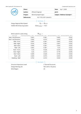
  • 1. Created with ClearCalcs.comWind Loads (AS1170.2) (version 19) Client: Date: Apr 7, 2020 Author: Efficient Engineer Job #: Project: Wind Example Project Subject: Webinar Example 1 References: AS 1170.2:2011 (Amdt 5) Design Regional Wind Speed   AS4055 Wind Class Equivalent N2.5  Wind Loads for Load Linking Surface Label Max Ultimate Wind ( ) Min Ultimate Wind ( ) Max Service Wind ( ) Min Service Wind ( ) Wall - Any Direction 0.587 -0.381 0.403 -0.262 Roof - Any Direction 0.369 -0.575 0.253 -0.395 Wall - Front 0.587 -0.381 0.403 -0.262 Wall - Right 0.535 -0.381 0.367 -0.262 Wall - Back 0.499 -0.381 0.343 -0.262 Wall - Left 0.465 -0.381 0.32 -0.262 Roof - Front 0.34 -0.528 0.234 -0.363 Roof - Right 0.26 -0.575 0.178 -0.395 Roof - Back 0.289 -0.528 0.199 -0.363 Roof - Left 0.369 -0.575 0.253 -0.395 Cladding - Wall 0.792 -0.572 0.544 -0.393 Structure Importance Level Design Working Life Wind Region   V ​ =R 45 m/s class ​ =AS4055 W ​ =table W ​ u,down kPa W ​ u,up kPa W ​ s,down kPa W ​ s,up kPa   2: Normal Structures NCC 2019 (~50 years) A5 Summary Key Inputs 1
  • 2. Building Directions, Dimensions, and Compass Directions 45 b d Right θ = 90° Back θ = 180° Front θ = 0 Left θ = 270° W β = 270° S β = 180° N β = 0° NW β = 315° SW β = 225° Compass Orientation of "Front" of Building (see description)   Breadth of Building (Left to Right)   Depth of Building (Front to Back)   Average Roof Height of Building   Roof Type Roof Pitch   Maximum Ratio of Area of Openings on One Surface to Sum of Total Open Area of All Other Surfaces   Surface on Which Largest Openings Area Exists Overall Building Permeability Elevated Building? Calculate Wind Load at Heights Height for Calculations ( ) 6 Minimum Ultimate Limit State Recurrence Interval   Ultimate Limit State Recurrence Interval   Serviceability Limit State Recurrence Interval   β ​ =θ=0 10 deg b = 14 m d = 10 m h = 6 m Gable/Monoslope α = 30 deg (A ​/ΣA ​) ​ =o o max 0.5 Front   Permeable: Openings in any surface > 0.5% of area No z ​ =table z m R ​ =min 500 years R = 500 years R ​ =serv 25 years Parameters for Special Buildings 2
  • 3. Lowest Terrain Category Smallest Number of Shielding Buildings within a 45° Arc and 20*h Radius   Shortest Average Height of Shielding Buildings   Smallest Average Breadth of Shielding Buildings, Normal to Wind Stream   Highest Height of Hills, Ridges, or Escarpments   Shortest Horizontal Upwind Distance from Crest to a Level Half the Height Below the Crest   Shortest Horizontal Distance from Crest to Structure Being Designed   Wind Loads for Load Linking Surface Label Surface Type Internal Comb Factor External Comb Factor Other External Factors Wall - Any Direction Wall - Any Direction 1 1 1 Roof - Any Direction Roof - Any Direction 1 1 1 Wall - Front Wall - Front 1 1 1 Wall - Right Wall - Right 1 1 1 Wall - Back Wall - Back 1 1 1 Wall - Left Wall - Left 1 1 1 Roof - Front Roof - Front 1 1 1 Roof - Right Roof - Right 1 1 1 Roof - Back Roof - Back 1 1 1 Roof - Left Roof - Left 1 1 1 Cladding - Wall Wall - Any Direction 1 1 1.5 Terrain Category to North Terrain Category to Northeast Terrain Category to East Terrain Category to Southeast Terrain Category to South Terrain Category to Southwest Terrain Category to West Terrain Category to Northwest   TC3: Numerous closely-spaced obstructions (suburbs) n ​ =s 30 h ​ =s 6 m b ​ =s 10 m H = 0 m L ​ =u 10 m x = 0 m   W ​ =table K ​ c,i K ​ c,e K ​K ​K ​ l p r   TC3: Numerous closely-spaced obstructions (suburbs) TC3: Numerous closely-spaced obstructions (suburbs) TC3: Numerous closely-spaced obstructions (suburbs) TC3: Numerous closely-spaced obstructions (suburbs) TC3: Numerous closely-spaced obstructions (suburbs) TC3: Numerous closely-spaced obstructions (suburbs) TC3: Numerous closely-spaced obstructions (suburbs) TC3: Numerous closely-spaced obstructions (suburbs) Terrain Properties - Worst Case of All Directions (AS 1170.2:2011, Cl 4) Wind Loads for Linking to Other Calculators Terrain Properties - For Each Direction (AS 1170.2:2011, Cl 4) 3
  • 4. Shielding Buildings Direction No. of Shielding Buildings Avg. Roof Height ( ) Avg. Breadth ( ) Avg. Spacing ( ) Shielding Parameter Shielding Multiplier 30 6 10 32 4.13 0.838 30 6 10 32 4.13 0.838 30 6 10 32 4.13 0.838 30 6 10 32 4.13 0.838 30 6 10 32 4.13 0.838 30 6 10 32 4.13 0.838 30 6 10 32 4.13 0.838 30 6 10 32 4.13 0.838 Hill Shape Direction Topographic Feature Height of Feature ( ) Horiz. Dist. Crest → Half Height ( ) Horiz. Dist. Structure → Crest ( ) Length Scale Vertical ( ) Length Scale Horizontal ( ) Hill-Shape Multiplier Hill/Ridge 0 10 0 3.6 28.8 1 Hill/Ridge 0 10 0 3.6 28.8 1 Hill/Ridge 0 10 0 3.6 28.8 1 Hill/Ridge 0 10 0 3.6 28.8 1 Hill/Ridge 0 10 0 3.6 28.8 1 Hill/Ridge 0 10 0 3.6 28.8 1 Hill/Ridge 0 10 0 3.6 28.8 1 Hill/Ridge 0 10 0 3.6 28.8 1 Topographic Multiplier Direction Hill Multiplier Lee Multiplier (NZ Only) Topographic Multiplier 1 1 1 1 1 1 1 1 1 1 1 1 1 1 1 1 1 1 1 1 1 1 1 1 M ​ =s,table n ​ s h ​ s m b ​ s m l ​ s m s M ​ s N NE E SE S SW W NW M ​ =h,table H m L ​ u m x m L ​ 1 m L ​ 2 m M ​ h N NE E SE S SW W NW M ​ =t,table M ​ h M ​ lee M ​ t N NE E SE S SW W NW 4
  • 5. Site Wind Speed Direction Direction Multiplier Terrain/Height Multiplier Shielding Multiplier Topographic Multiplier Site Wind Speed ( ) Serviceability Site Wind Speed ( ) 1 0.83 0.838 1 31.3 25.9 0.85 0.83 0.838 1 26.6 22 0.8 0.83 0.838 1 25 20.7 0.8 0.83 0.838 1 25 20.7 0.85 0.83 0.838 1 26.6 22 0.9 0.83 0.838 1 28.1 23.3 1 0.83 0.838 1 31.3 25.9 0.95 0.83 0.838 1 29.7 24.6 Design Wind Speeds Building Plan Face Orientation ( ) Plan Cardinal Direction ( ) Wind at 45° to Left ( ) Wind within Central 90° ( ) Wind at 45° to Right ( ) Design Wind Speed ( ) 0 10 30.1 31.3 26.2 31.3 90 100 26.2 25 25.4 26.2 180 190 25.4 26.6 28.8 28.8 270 280 28.8 31.3 30.1 31.3 Serviceability Wind Speeds Building Plan Face Orientation ( ) Plan Cardinal Direction ( ) Wind at 45° to Left ( ) Wind within Central 90° ( ) Wind at 45° to Right ( ) Service Wind Speed ( ) 0 10 24.9 25.9 21.7 25.9 90 100 21.7 20.7 21 21.7 180 190 21 22 23.9 23.9 270 280 23.9 25.9 24.9 25.9 Area of Openings in Surfaces Building Surface Area of Openings ( ) 0 0 0 0 0 0 0 0 Maximum Ratio of Area of Openings on One Surface to the Sum of Total Openings on Other Surfaces     V ​ =sit,β M ​ d M ​ z,cat M ​ s M ​ t V ​ sit,β m/s V ​ sit,β,serv m/s N NE E SE S SW W NW V ​ =des,θ,table θ deg β deg V ​ sit,θ−45 m/s V ​ sit,θ m/s V ​ sit,θ+45 m/s V ​ des,θ m/s Front Right Back Left V ​ =des,θ,serv,table θ deg β deg V ​ sit,θ−45,serv m/s V ​ sit,θ,serv m/s V ​ sit,θ+45,serv m/s V ​ des,θ,serv m/s Front Right Back Left   A ​ =o A ​ o m2 Front Right Back Left Roof − FrontSide Roof − RightSide Roof − BackSide Roof − LeftSide A ​ =o,ratio,max 0.5 Site & Design Wind Speed (AS 1170.2:2011, Cl 2.2-2.3) Design Internal Wind Pressure (AS 1170.2:2011, Cl 2.4) 5
  • 6. Internal Pressure Coefficients Windward Face Internal Pressure #1 Internal Pressure #2 Front -0.3 0 Right -0.3 0 Back -0.3 0 Left -0.3 0 Design Internal Wind Pressure Windward Face Dynamic Shape Factor Design Wind Speed ( ) Design Int Wind #1 ( ) Design Int Wind #2 ( ) Front 1 31.3 -0.176 0 Right 1 26.2 -0.124 0 Back 1 28.8 -0.15 0 Left 1 31.3 -0.176 0 Minimum Design Internal Wind Pressure   Maximum Design Internal Wind Pressure   Serviceability Internal Wind Pressure Windward Face Dynamic Shape Factor Service Wind Speed ( ) Service Int Wind #1 ( ) Service Int Wind #2 ( ) Front 1 25.9 -0.121 0 Right 1 21.7 -0.0851 0 Back 1 23.9 -0.103 0 Left 1 25.9 -0.121 0 Minimum Serviceability Internal Wind Pressure   Maximum Serviceability Internal Wind Pressure   External Pressure Coefficient - Windward Wall   External Pressure Coefficient - Leeward Wall (front/back of building)   External Pressure Coefficient - Leeward Wall (left/right of building)   External Pressure Coefficient - Maximum Side Wall   External Pressure Coefficients on Walls Windward Face Front External Pressure Left External Pressure Back External Pressure Right External Pressure Front 0.7 -0.65 -0.5 -0.65 Right -0.65 -0.557 -0.65 0.7 Back -0.5 -0.65 0.7 -0.65 Left -0.65 0.7 -0.65 -0.557 Design External Wind Pressure for Walls Windward Wall Dynamic Shape Factor Design Wind Speed ( ) Design Front External Wind Pressure ( ) Design Right External Wind Pressure ( ) Design Back External Wind Pressure ( ) Design Left External Wind Pressure ( ) Front 1 31.3 0.411 -0.381 -0.293 -0.381 Right 1 26.2 -0.268 -0.23 -0.268 0.289 Back 1 28.8 -0.25 -0.324 0.349 -0.324 Left 1 31.3 -0.381 0.411 -0.381 -0.327 C ​ =pi,table C ​ pi,1 C ​ pi,2 p ​ =i,table C ​ dyn V ​ des,θ m/s p ​ i,1 kPa p ​ i,2 kPa p ​ =i,1 −0.176 kPa p ​ =i,2 0 kPa p ​ =i,serv,table C ​ dyn V ​ des,θ m/s p ​ i,serv,1 kPa p ​ i,serv,2 kPa p ​ =i,serv,1 −0.121 kPa p ​ =i,serv,2 0 kPa   C ​ =pe,W 0.7 C ​ =pe,fb,L −0.5 C ​ =pe,lr,L −0.557 C ​ =pe,S −0.65 C ​ =pe,table C ​ pe,Front C ​ pe,Left C ​ pe,Back C ​ pe,Right p ​ =e,table C ​ dyn V ​ des,θ m/s p ​ e,Front kPa p ​ e,Right kPa p ​ e,Back kPa p ​ e,Left kPa Design External Wind Pressure on Walls (AS 1170.2:2011, Cl 2.4) 6
  • 7. Design External Wind Pressures on Each Wall Surface Minimum External Pressure ( ) Maximum External Pressure ( ) Front -0.381 0.411 Right -0.381 0.411 Back -0.381 0.349 Left -0.381 0.289 Minimum Design External Wind Pressure on All Walls   Maximum Design External Wind Pressure on All Walls   Design External Wind Pressure for Walls Windward Wall Dynamic Shape Factor Design Wind Speed ( ) Design Front External Wind Pressure ( ) Design Right External Wind Pressure ( ) Design Back External Wind Pressure ( ) Design Left External Wind Pressure ( ) Front 1 25.9 0.282 -0.262 -0.202 -0.262 Right 1 21.7 -0.184 -0.158 -0.184 0.199 Back 1 23.9 -0.171 -0.223 0.24 -0.223 Left 1 25.9 -0.262 0.282 -0.262 -0.225 Serviceability External Wind Pressures on Each Wall Surface Minimum External Pressure ( ) Maximum External Pressure ( ) Front -0.262 0.282 Right -0.262 0.282 Back -0.262 0.24 Left -0.262 0.199 Minimum Serviceability External Wind Pressure on All Walls   Maximum Serviceability External Wind Pressure on All Walls   External Pressure Coefficients on Roof Windward Wall Front Pressure #1 Front Pressure #2 Right Pressure #1 Right Pressure #2 Back Pressure #1 Back Pressure #2 Left Pressure #1 Left Pressure #2 Front -0.22 0.28 -0.98 -0.44 -0.6 -0.6 -0.98 -0.44 Right -0.9 -0.4 -0.2 0.329 -0.9 -0.4 -0.6 -0.6 Back -0.6 -0.6 -0.98 -0.44 -0.22 0.28 -0.98 -0.44 Left -0.9 -0.4 -0.6 -0.6 -0.9 -0.4 -0.2 0.329 Design External Pressures on Roof Windward Wall Front Pressure #1 ( ) Front Pressure #2 ( ) Right Pressure #1 ( ) Right Pressure #2 ( ) Back Pressure #1 ( ) Back Pressure #2 ( ) Left Pressure #1 ( ) Left Pressure #2 ( ) Front -0.129 0.164 -0.575 -0.258 -0.352 -0.352 -0.575 -0.258 Right -0.372 -0.165 -0.0826 0.136 -0.372 -0.165 -0.248 -0.248 Back -0.299 -0.299 -0.489 -0.22 -0.11 0.14 -0.489 -0.22 Left -0.528 -0.235 -0.352 -0.352 -0.528 -0.235 -0.117 0.193 p ​ =e,walls p ​ e,min kPa p ​ e,max kPa p ​ =e,walls,1 −0.381 kPa p ​ =e,walls,2 0.411 kPa p ​ =e,serv,table C ​ dyn V ​ des,θ m/s p ​ e,serv,Front kPa p ​ e,serv,Right kPa p ​ e,serv,Back kPa p ​ e,serv,Left kPa p ​ =e,serv,walls p ​ e,serv,min kPa p ​ e,serv,max kPa p ​ =e,walls,serv,1 −0.262 kPa p ​ =e,walls,serv,2 0.282 kPa   C ​ =pe,roof,table C ​ pe,rF,1 C ​ pe,rF,2 C ​ pe,rR,1 C ​ pe,rR,2 C ​ pe,rB,1 C ​ pe,rB,2 C ​ pe,rL,1 C ​ pe,rL,2 p ​ =e,roof,table p ​ e,rF,1 kPa p ​ e,rF,2 kPa p ​ e,rR,1 kPa p ​ e,rR,2 kPa p ​ e,rB,1 kPa p ​ e,rB,2 kPa p ​ e,rL,1 kPa p ​ e,rL,2 kPa Design External Wind Pressure on Roof (AS 1170.2:2011, Cl 2.4) 7
  • 8. Design External Wind Pressures on Each Side of the Roof Side of Roof Minimum External Pressure ( ) Maximum External Pressure ( ) Front -0.528 0.164 Right -0.575 0.136 Back -0.528 0.14 Left -0.575 0.193 Minimum Design External Wind Pressure on Entire Roof   Maximum Design External Wind Pressure on Entire Roof   Design External Pressures on Roof Windward Wall Front Pressure #1 ( ) Front Pressure #2 ( ) Right Pressure #1 ( ) Right Pressure #2 ( ) Back Pressure #1 ( ) Back Pressure #2 ( ) Left Pressure #1 ( ) Left Pressure #2 ( ) Front -0.0887 0.113 -0.395 -0.177 -0.242 -0.242 -0.395 -0.177 Right -0.255 -0.114 -0.0568 0.0932 -0.255 -0.114 -0.17 -0.17 Back -0.206 -0.206 -0.336 -0.151 -0.0754 0.096 -0.336 -0.151 Left -0.363 -0.161 -0.242 -0.242 -0.363 -0.161 -0.0806 0.132 Design External Wind Pressures on Each Side of the Roof Side of Roof Minimum External Pressure ( ) Maximum External Pressure ( ) Front -0.363 0.113 Right -0.395 0.0932 Back -0.363 0.096 Left -0.395 0.132 Minimum Serviceability External Wind Pressure on Entire Roof   Maximum Serviceability External Wind Pressure on Entire Roof   Frictional Drag Load Required for Wind from Front or Back No  Frictional Drag Load Required for Wind from Left or Right No  Design Frictional Drag Wind Pressure Windward Wall Dynamic Shape Factor Coefficient Area Reduction Factor Design Wind Speed ( ) Side Frictional Drag Pressure ( ) Front 1 0 0 31.3 0 Right 1 0 0 26.2 0 Back 1 0 0 28.8 0 Left 1 0 0 31.3 0 Comments p ​ =e,roof p ​ e,min kPa p ​ e,max kPa p ​ =e,roof,1 −0.575 kPa p ​ =e,roof,2 0.193 kPa p ​ =e,roof,serv,table p ​ e,rF,serv,1 kPa p ​ e,rF,serv,2 kPa p ​ e,rR,serv,1 kPa p ​ e,rR,serv,2 kPa p ​ e,rB,serv,1 kPa p ​ e,rB,serv,2 kPa p ​ e,rL,serv,1 kPa p ​ e,rL,serv,2 kPa p ​ =e,roof,serv p ​ e,serv,min kPa p ​ e,serv,max kPa p ​ =e,roof,serv,1 −0.395 kPa p ​ =e,roof,serv,2 0.132 kPa   C ​ =f,fb,flag C ​ =f,lr,flag f ​ =table C ​ dyn C ​ f K ​ a V ​ des,θ m/s f kPa   Design Frictional Drag (AS 1170.2:2011, Cl 5.5) Comments 8
  • 9. Created with ClearCalcs.comWind Loads (AS1170.2) (version 19) Client: Date: Apr 7, 2020 Author: Efficient Engineer Job #: Project: Wind Example Project #2 Subject: QLD Wind Example #2 References: AS 1170.2:2011 (Amdt 5) Design Regional Wind Speed   AS4055 Wind Class Equivalent C2.6  Wind Loads for Load Linking Surface Label Max Ultimate Wind ( ) Min Ultimate Wind ( ) Max Service Wind ( ) Min Service Wind ( ) Wall - Any Direction 3.77 -3.08 1.7 -1.39 Roof - Any Direction 1.48 -3.11 0.666 -1.4 Wall - Front 0.541 -3.08 0.244 -1.39 Wall - Right 3.1 -0.53 1.4 -0.239 Wall - Back 2 -1.21 0.901 -0.547 Wall - Left 3.05 0.14 1.37 0.0629 Roof - Front -2.06 -3.11 -0.931 -1.4 Roof - Right 0.808 -0.251 0.364 -0.113 Roof - Back -0.0235 -0.835 -0.0106 -0.376 Roof - Left 1.28 0.0634 0.577 0.0286 Structure Importance Level Design Working Life Wind Region   V ​ =R 69.4 m/s class ​ =AS4055 W ​ =table W ​ u,down kPa W ​ u,up kPa W ​ s,down kPa W ​ s,up kPa   2: Normal Structures NCC 2019 (~50 years) C Summary Key Inputs 1
  • 10. Building Directions, Dimensions, and Compass Directions 45 b d Right θ = 90° Back θ = 180° Front θ = 0 Left θ = 270° W β = 270° S β = 180° N β = 0° NW β = 315° SW β = 225° Compass Orientation of "Front" of Building (see description)   Breadth of Building (Left to Right)   Depth of Building (Front to Back)   Average Roof Height of Building   Roof Type Roof Pitch   Maximum Ratio of Area of Openings on One Surface to Sum of Total Open Area of All Other Surfaces   Surface on Which Largest Openings Area Exists Overall Building Permeability Elevated Building? Calculate Wind Load at Heights Height for Calculations ( ) 9 Minimum Ultimate Limit State Recurrence Interval   Ultimate Limit State Recurrence Interval   Serviceability Limit State Recurrence Interval   β ​ =θ=0 15 deg b = 22 m d = 17 m h = 9 m Hip α = 15 deg (A ​/ΣA ​) ​ =o o max 2 Front   Permeable: Openings in any surface > 0.5% of area No z ​ =table z m R ​ =min 500 years R = 500 years R ​ =serv 25 years Parameters for Special Buildings 2
  • 11. Lowest Terrain Category Smallest Number of Shielding Buildings within a 45° Arc and 20*h Radius   Shortest Average Height of Shielding Buildings   Smallest Average Breadth of Shielding Buildings, Normal to Wind Stream   Highest Height of Hills, Ridges, or Escarpments   Shortest Horizontal Upwind Distance from Crest to a Level Half the Height Below the Crest   Shortest Horizontal Distance from Crest to Structure Being Designed   Wind Loads for Load Linking Surface Label Surface Type Internal Comb Factor External Comb Factor Other External Factors Wall - Any Direction Wall - Any Direction 1 1 1 Roof - Any Direction Roof - Any Direction 1 1 1 Wall - Front Wall - Front 1 1 1 Wall - Right Wall - Right 1 1 1 Wall - Back Wall - Back 1 1 1 Wall - Left Wall - Left 1 1 1 Roof - Front Roof - Front 1 1 1 Roof - Right Roof - Right 1 1 1 Roof - Back Roof - Back 1 1 1 Roof - Left Roof - Left 1 1 1 Terrain Category to North Terrain Category to Northeast Terrain Category to East Terrain Category to Southeast Terrain Category to South Terrain Category to Southwest Terrain Category to West Terrain Category to Northwest   TC3: Numerous closely-spaced obstructions (suburbs) n ​ =s 0 h ​ =s 9 m b ​ =s 20 m H = 0 m L ​ =u 10 m x = 0 m   W ​ =table K ​ c,i K ​ c,e K ​K ​K ​ l p r   TC3: Numerous closely-spaced obstructions (suburbs) TC3: Numerous closely-spaced obstructions (suburbs) TC3: Numerous closely-spaced obstructions (suburbs) TC3: Numerous closely-spaced obstructions (suburbs) TC3: Numerous closely-spaced obstructions (suburbs) TC2.5: Isolated trees or obstructions (outer suburbs) TC2: Open terrain with scattered obstructions (farmland) TC2.5: Isolated trees or obstructions (outer suburbs) Terrain Properties - Worst Case of All Directions (AS 1170.2:2011, Cl 4) Wind Loads for Linking to Other Calculators Terrain Properties - For Each Direction (AS 1170.2:2011, Cl 4) 3
  • 12. Shielding Buildings Direction No. of Shielding Buildings Avg. Roof Height ( ) Avg. Breadth ( ) Avg. Spacing ( ) Shielding Parameter Shielding Multiplier 0 9 20 180 13.4 1 10 9 20 54 4.02 1 30 9 20 48 3.58 0.819 30 9 20 48 3.58 0.819 30 9 20 48 3.58 0.819 10 9 20 54 4.02 0.834 0 9 20 180 13.4 1 0 9 20 180 13.4 1 Hill Shape Direction Topographic Feature Height of Feature ( ) Horiz. Dist. Crest → Half Height ( ) Horiz. Dist. Structure → Crest ( ) Length Scale Vertical ( ) Length Scale Horizontal ( ) Hill-Shape Multiplier Hill/Ridge 120 200 400 72 576 1.13 Hill/Ridge 185 200 1 000 74 592 0.561 Hill/Ridge 0 10 0 3.6 28.8 1 Hill/Ridge 0 10 0 3.6 28.8 1 Hill/Ridge 0 10 0 3.6 28.8 1 Hill/Ridge 0 10 0 3.6 28.8 1 Hill/Ridge 0 10 0 3.6 28.8 1 Hill/Ridge 50 400 600 144 1 150 1.04 Topographic Multiplier Direction Hill Multiplier Lee Multiplier (NZ Only) Topographic Multiplier 1.13 1 1.13 0.561 1 1 1 1 1 1 1 1 1 1 1 1 1 1 1 1 1 1.04 1 1.04 M ​ =s,table n ​ s h ​ s m b ​ s m l ​ s m s M ​ s N NE E SE S SW W NW M ​ =h,table H m L ​ u m x m L ​ 1 m L ​ 2 m M ​ h N NE E SE S SW W NW M ​ =t,table M ​ h M ​ lee M ​ t N NE E SE S SW W NW 4
  • 13. Site Wind Speed Direction Direction Multiplier Terrain/Height Multiplier Shielding Multiplier Topographic Multiplier Site Wind Speed ( ) Serviceability Site Wind Speed ( ) 1 0.83 1 1.13 65.1 43.7 1 0.83 1 1 57.6 38.7 1 0.83 0.819 1 47.2 31.7 1 0.83 0.819 1 47.2 31.7 1 0.83 0.819 1 47.2 31.7 1 0.906 0.834 1 52.5 35.2 1 0.982 1 1 68.2 45.8 1 0.906 1 1.04 65.7 44.1 Design Wind Speeds Building Plan Face Orientation ( ) Plan Cardinal Direction ( ) Wind at 45° to Left ( ) Wind within Central 90° ( ) Wind at 45° to Right ( ) Design Wind Speed ( ) 0 15 65.5 65.1 54.2 65.5 90 105 54.2 47.2 47.2 54.2 180 195 47.2 47.2 57.7 57.7 270 285 57.7 68.2 65.5 68.2 Serviceability Wind Speeds Building Plan Face Orientation ( ) Plan Cardinal Direction ( ) Wind at 45° to Left ( ) Wind within Central 90° ( ) Wind at 45° to Right ( ) Service Wind Speed ( ) 0 15 44 43.7 36.4 44 90 105 36.4 31.7 31.7 36.4 180 195 31.7 31.7 38.8 38.8 270 285 38.8 45.8 44 45.8 Large, Permanently-Open Ventilators Present per Cl 5.3.1.3? Area of Openings in Surfaces Building Surface Area of Openings ( ) 0 0 0 0 0 0 0 0 Maximum Ratio of Area of Openings on One Surface to the Sum of Total Openings on Other Surfaces     V ​ =sit,β M ​ d M ​ z,cat M ​ s M ​ t V ​ sit,β m/s V ​ sit,β,serv m/s N NE E SE S SW W NW V ​ =des,θ,table θ deg β deg V ​ sit,θ−45 m/s V ​ sit,θ m/s V ​ sit,θ+45 m/s V ​ des,θ m/s Front Right Back Left V ​ =des,θ,serv,table θ deg β deg V ​ sit,θ−45,serv m/s V ​ sit,θ,serv m/s V ​ sit,θ+45,serv m/s V ​ des,θ,serv m/s Front Right Back Left   No A ​ =o A ​ o m2 Front Right Back Left Roof − FrontSide Roof − RightSide Roof − BackSide Roof − LeftSide A ​ =o,ratio,max 2 Site & Design Wind Speed (AS 1170.2:2011, Cl 2.2-2.3) Design Internal Wind Pressure (AS 1170.2:2011, Cl 2.4) 5
  • 14. Internal Pressure Coefficients Windward Face Internal Pressure #1 Internal Pressure #2 Front 0.49 0.49 Right -0.65 -0.65 Back -0.3 -0.3 Left -0.65 -0.65 Design Internal Wind Pressure Windward Face Dynamic Shape Factor Design Wind Speed ( ) Design Int Wind #1 ( ) Design Int Wind #2 ( ) Front 1 65.5 1.26 1.26 Right 1 54.2 -1.14 -1.14 Back 1 57.7 -0.6 -0.6 Left 1 68.2 -1.81 -1.81 Minimum Design Internal Wind Pressure   Maximum Design Internal Wind Pressure   Serviceability Internal Wind Pressure Windward Face Dynamic Shape Factor Service Wind Speed ( ) Service Int Wind #1 ( ) Service Int Wind #2 ( ) Front 1 44 0.569 0.569 Right 1 36.4 -0.516 -0.516 Back 1 38.8 -0.27 -0.27 Left 1 45.8 -0.817 -0.817 Minimum Serviceability Internal Wind Pressure   Maximum Serviceability Internal Wind Pressure   External Pressure Coefficient - Windward Wall   External Pressure Coefficient - Leeward Wall (front/back of building)   External Pressure Coefficient - Leeward Wall (left/right of building)   External Pressure Coefficient - Maximum Side Wall   External Pressure Coefficients on Walls Windward Face Front External Pressure Left External Pressure Back External Pressure Right External Pressure Front 0.7 -0.65 -0.3 -0.65 Right -0.65 -0.545 -0.65 0.7 Back -0.3 -0.65 0.7 -0.65 Left -0.65 0.7 -0.65 -0.545 Design External Wind Pressure for Walls Windward Wall Dynamic Shape Factor Design Wind Speed ( ) Design Front External Wind Pressure ( ) Design Right External Wind Pressure ( ) Design Back External Wind Pressure ( ) Design Left External Wind Pressure ( ) Front 1 65.5 1.8 -1.67 -0.773 -1.67 Right 1 54.2 -1.14 -0.96 -1.14 1.23 Back 1 57.7 -0.6 -1.3 1.4 -1.3 Left 1 68.2 -1.81 1.95 -1.81 -1.52 C ​ =pi,table C ​ pi,1 C ​ pi,2 p ​ =i,table C ​ dyn V ​ des,θ m/s p ​ i,1 kPa p ​ i,2 kPa p ​ =i,1 −1.81 kPa p ​ =i,2 1.26 kPa p ​ =i,serv,table C ​ dyn V ​ des,θ m/s p ​ i,serv,1 kPa p ​ i,serv,2 kPa p ​ =i,serv,1 −0.817 kPa p ​ =i,serv,2 0.569 kPa   C ​ =pe,W 0.7 C ​ =pe,fb,L −0.3 C ​ =pe,lr,L −0.545 C ​ =pe,S −0.65 C ​ =pe,table C ​ pe,Front C ​ pe,Left C ​ pe,Back C ​ pe,Right p ​ =e,table C ​ dyn V ​ des,θ m/s p ​ e,Front kPa p ​ e,Right kPa p ​ e,Back kPa p ​ e,Left kPa Design External Wind Pressure on Walls (AS 1170.2:2011, Cl 2.4) 6
  • 15. Design External Wind Pressures on Each Wall Surface Minimum External Pressure ( ) Maximum External Pressure ( ) Front -1.81 1.8 Right -1.67 1.95 Back -1.81 1.4 Left -1.67 1.23 Minimum Design External Wind Pressure on All Walls   Maximum Design External Wind Pressure on All Walls   Design External Wind Pressure for Walls Windward Wall Dynamic Shape Factor Design Wind Speed ( ) Design Front External Wind Pressure ( ) Design Right External Wind Pressure ( ) Design Back External Wind Pressure ( ) Design Left External Wind Pressure ( ) Front 1 44 0.813 -0.755 -0.348 -0.755 Right 1 36.4 -0.516 -0.433 -0.516 0.555 Back 1 38.8 -0.27 -0.586 0.631 -0.586 Left 1 45.8 -0.817 0.88 -0.817 -0.686 Serviceability External Wind Pressures on Each Wall Surface Minimum External Pressure ( ) Maximum External Pressure ( ) Front -0.817 0.813 Right -0.755 0.88 Back -0.817 0.631 Left -0.755 0.555 Minimum Serviceability External Wind Pressure on All Walls   Maximum Serviceability External Wind Pressure on All Walls   External Pressure Coefficients on Roof Windward Wall Front Pressure #1 Front Pressure #2 Right Pressure #1 Right Pressure #2 Back Pressure #1 Back Pressure #2 Left Pressure #1 Left Pressure #2 Front -0.718 -0.312 -0.506 -0.506 -0.506 -0.506 -0.506 -0.506 Right -0.5 -0.5 -0.627 -0.191 -0.5 -0.5 -0.5 -0.5 Back -0.506 -0.506 -0.506 -0.506 -0.718 -0.312 -0.506 -0.506 Left -0.5 -0.5 -0.5 -0.5 -0.5 -0.5 -0.627 -0.191 Design External Pressures on Roof Windward Wall Front Pressure #1 ( ) Front Pressure #2 ( ) Right Pressure #1 ( ) Right Pressure #2 ( ) Back Pressure #1 ( ) Back Pressure #2 ( ) Left Pressure #1 ( ) Left Pressure #2 ( ) Front -1.85 -0.803 -1.3 -1.3 -1.3 -1.3 -1.3 -1.3 Right -0.88 -0.88 -1.1 -0.336 -0.88 -0.88 -0.88 -0.88 Back -1.01 -1.01 -1.01 -1.01 -1.43 -0.623 -1.01 -1.01 Left -1.4 -1.4 -1.4 -1.4 -1.4 -1.4 -1.75 -0.533 p ​ =e,walls p ​ e,min kPa p ​ e,max kPa p ​ =e,walls,1 −1.81 kPa p ​ =e,walls,2 1.95 kPa p ​ =e,serv,table C ​ dyn V ​ des,θ m/s p ​ e,serv,Front kPa p ​ e,serv,Right kPa p ​ e,serv,Back kPa p ​ e,serv,Left kPa p ​ =e,serv,walls p ​ e,serv,min kPa p ​ e,serv,max kPa p ​ =e,walls,serv,1 −0.817 kPa p ​ =e,walls,serv,2 0.88 kPa   C ​ =pe,roof,table C ​ pe,rF,1 C ​ pe,rF,2 C ​ pe,rR,1 C ​ pe,rR,2 C ​ pe,rB,1 C ​ pe,rB,2 C ​ pe,rL,1 C ​ pe,rL,2 p ​ =e,roof,table p ​ e,rF,1 kPa p ​ e,rF,2 kPa p ​ e,rR,1 kPa pe,rR,2 kPa p ​ e,rB,1 kPa p ​ e,rB,2 kPa p ​ e,rL,1 kPa p ​ e,rL,2 kPa Design External Wind Pressure on Roof (AS 1170.2:2011, Cl 2.4) 7
  • 16. Design External Wind Pressures on Each Side of the Roof Side of Roof Minimum External Pressure ( ) Maximum External Pressure ( ) Front -1.85 -0.803 Right -1.4 -0.336 Back -1.43 -0.623 Left -1.75 -0.533 Minimum Design External Wind Pressure on Entire Roof   Maximum Design External Wind Pressure on Entire Roof   Design External Pressures on Roof Windward Wall Front Pressure #1 ( ) Front Pressure #2 ( ) Right Pressure #1 ( ) Right Pressure #2 ( ) Back Pressure #1 ( ) Back Pressure #2 ( ) Left Pressure #1 ( ) Left Pressure #2 ( ) Front -0.833 -0.362 -0.587 -0.587 -0.587 -0.587 -0.587 -0.587 Right -0.397 -0.397 -0.498 -0.151 -0.397 -0.397 -0.397 -0.397 Back -0.456 -0.456 -0.456 -0.456 -0.647 -0.281 -0.456 -0.456 Left -0.629 -0.629 -0.629 -0.629 -0.629 -0.629 -0.789 -0.24 Design External Wind Pressures on Each Side of the Roof Side of Roof Minimum External Pressure ( ) Maximum External Pressure ( ) Front -0.833 -0.362 Right -0.629 -0.151 Back -0.647 -0.281 Left -0.789 -0.24 Minimum Serviceability External Wind Pressure on Entire Roof   Maximum Serviceability External Wind Pressure on Entire Roof   Frictional Drag Load Required for Wind from Front or Back No  Frictional Drag Load Required for Wind from Left or Right No  Design Frictional Drag Wind Pressure Windward Wall Dynamic Shape Factor Coefficient Area Reduction Factor Design Wind Speed ( ) Side Frictional Drag Pressure ( ) Front 1 0 0 65.5 0 Right 1 0 0 54.2 0 Back 1 0 0 57.7 0 Left 1 0 0 68.2 0 Comments p ​ =e,roof p ​ e,min kPa p ​ e,max kPa p ​ =e,roof,1 −1.85 kPa p ​ =e,roof,2 −0.336 kPa p ​ =e,roof,serv,table p ​ e,rF,serv,1 kPa p ​ e,rF,serv,2 kPa p ​ e,rR,serv,1 kPa p ​ e,rR,serv,2 kPa p ​ e,rB,serv,1 kPa p ​ e,rB,serv,2 kPa p ​ e,rL,serv,1 kPa p ​ e,rL,serv,2 kPa p ​ =e,roof,serv p ​ e,serv,min kPa p ​ e,serv,max kPa p ​ =e,roof,serv,1 −0.833 kPa p ​ =e,roof,serv,2 −0.151 kPa   C ​ =f,fb,flag C ​ =f,lr,flag f ​ =table C ​ dyn C ​ f K ​ a V ​ des,θ m/s f kPa   Design Frictional Drag (AS 1170.2:2011, Cl 5.5) Comments 8