1. 1 Froth Flotation – Fundamental Principles
Froth flotation is a highly versatile method for physically separating particles based on
differences in the ability of air bubbles to selectively adhere to specific mineral surfaces in a
mineral/water slurry. The particles with attached air bubbles are then carried to the surface and
removed, while the particles that remain completely wetted stay in the liquid phase. Froth
flotation can be adapted to a broad range of mineral separations, as it is possible to use chemical
treatments to selectively alter mineral surfaces so that they have the necessary properties for the
separation. It is currently in use for many diverse applications, with a few examples being:
separating sulfide minerals from silica gangue (and from other sulfide minerals); separating
potassium chloride (sylvite) from sodium chloride (halite); separating coal from ash-forming
minerals; removing silicate minerals from iron ores; separating phosphate minerals from
silicates; and even non-mineral applications such as de-inking recycled newsprint. It is
particularly useful for processing fine-grained ores that are not amenable to conventional gravity
concentration.
1
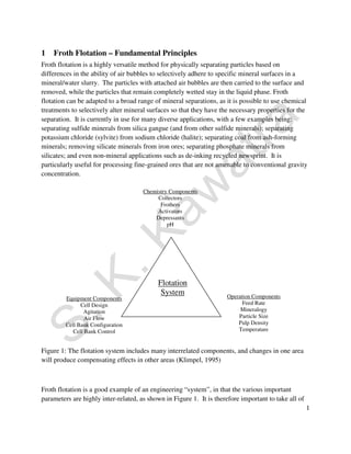
Chemistry Components
Collectors
Frothers
Activators
Depressants
pH
Equipment Components
Cell Design
Agitation
Air Flow
Cell Bank Configuration
Cell Bank Control
Operation Components
Feed Rate
Mineralogy
Particle Size
Pulp Density
Temperature
Flotation
System
Figure 1: The flotation system includes many interrelated components, and changes in one area
will produce compensating effects in other areas (Klimpel, 1995)
Froth flotation is a good example of an engineering “system”, in that the various important
parameters are highly inter-related, as shown in Figure 1. It is therefore important to take all of
2. these factors into account in froth flotation operations. Changes in the settings of one factor (such
as feed rate) will automatically cause or demand changes in other parts of the system (such as
flotation rate, particle size recovery, air flow, pulp density, etc.) As a result, it is difficult to
study the effects of any single factor in isolation, and compensation effects within the system can
keep process changes from producing the expected effects (Klimpel, 1995). This makes it
difficult to develop predictive models for froth flotation, although work is being done to develop
simple models that can predict the performance of the circuit from easily-measurable parameters
such as solids recovery and tailings solid content (Rao et al., 1995).
2
1.1 Performance Calculations
There is no one universal method for expressing the effectiveness of a separation, but there are
several methods that are useful for examining froth flotation processes:
(a) Ratio of Concentration, the weight of the feed relative to the weight of the concentrate, The
Ratio of Concentration is F/C, where F is the total weight of the feed and C is the total weight of
the concentrate. One limitation with this calculation is that it uses the weights of the feed and
concentrate. While this data is available in laboratory experiments, in the plant it is likely that
the ore is not weighed and only assays will be available. However, it is possible to express the
ratio of concentration in terms of ore assays. Starting with the mass balance equations, and the
definition of the ratio of concentration:
F = C + T, Ff = Cc + Tt, Ratio of Concentration = F/C
where F, C, and T are the % weights of the feed, concentrate, and tailings, respectively; and f, c,
and t are the assays of the feed, concentrate, and tailings. We now need to eliminate T from these
equations so that we can solve for F/C:
Ff = Cc + Tt, and multiplying (F = C + T) by t gives us:
Ft = Ct + Tt, so subtracting this equation from the previous eliminates T and gives:
F(f - t) = C(c - t), and rearranging produces the equation for the ratio of concentration:
F/C = (c – t)/(f – t)
(b) % Metal Recovery, or percentage of the metal in the original feed that is recovered in the
concentrate. This can be calculated using weights and assays, as (Cc)/(Ff)·100. Or, since C/F =
(f – t)/(c – t), the % Metal Recovery can be calculated from assays alone using 100(c/f)(f – t)/(c –
t).
(c) % Metal Loss is the opposite of the % Metal Recovery, and represents the material lost to the
tailings. It can be calculated simply by subtracting the % Metal Recovery from 100%.
3. 3
(d) % Weight Recovery is essentially the inverse of the ratio of concentration, and equals
100·C/F = 100·(f – t)/(c – t).
(e) Enrichment Ratio is calculated directly from assays as c/f, weights are not involved in the
calculation.
Example Calculations:
Problem: A copper ore initially contains 2.09% Cu. After carrying out a froth flotation
separation, the products are as shown in Table 1. Using this data, calculate:
(a) Ratio of concentration
(b) % Metal Recovery
(c) % Metal Loss
(d) % Weight Recovery, or % Yield
(e) Enrichment Ratio
Table 1: Grade/recovery performance of a hypothetical copper ore flotation process.
Feed
f = 2.09% Cu
F = 100% Wt
Concentrate
c = 20% Cu
C = 10% Wt
Product % Weight % Cu Assay
Feed 100 2.09
Concentrate 10 20.0
Tailings 90 0.1
(a) From Table 1, the Ratio of Concentration can be calculated as F/C = 100/10 = 10. If only
assays are available, the ratio of concentration equals (20 – 0.1)/(2.09 – 0.1) = 10
So, for each 10 tons of feed, the plant would produce 1 ton of concentrate.
(b) Using the example data from Table 1, the % Cu recovery calculated from weights and assays
is:
% Cu Recovery = [(10·20)/(2.09·100)]·100 = 95.7%
Tailings
t = 0.1% Cu
T = 900% Wt
4. 4
The calculation using assays alone is
% Cu Recovery = 100(20/2.09)(2.09 – 0.1)/(20 – 0.1) = 95.7%
This means that 95.7% of the copper present in the ore was recovered in the concentrate, while
the rest was lost in the tailings.
(c) The % Cu Loss can be calculated by subtracting the % Cu Recovery from 100%:
% Cu Loss = 100 – 95.7 = 4.3%
This means that 4.3% of the copper present in the ore was lost in the tailings.
(d) The % Weight Recovery is equal to the % Weight of the concentrate in Table 1. It can also
be calculated from the assay values given in the table, as follows:
% Weight Recovery = 100·(2.09 - 0.1)(20 – 0.1) = 10%
(e) The Enrichment Ratio is calculated by dividing the concentrate assay in Table 1 by the feed
assay:
Enrichment Ratio = 20.0/2.09 = 9.57
This tells us that the concentrate has 9.57 times the copper concentration of the feed.
1.1.1 Grade/Recovery Curves
While each of these single calculated values are useful for comparing flotation performance for
different conditions, it is most useful to consider both the grade and the recovery simultaneously,
using a “Grade/Recovery Curve”. This is a graph of the recovery of the valuable metal achieved
versus the product grade at that recovery, and is particularly useful for comparing separations
where both the grade and the recovery are varying. A set of grade/recovery curves is shown in
Figure 2. If 100% of the feed is recovered to the product, then the product will obviously have
the same composition as the feed, and so the curve starts at the feed composition with 100%
recovery. Similarly, if the purest mineral grain that contains the metal of interest is removed, this
will be the maximum grade that can be produced by a physical separation, and so the 0%
recovery end of the curve terminates at an assay less than or equal to the assay of the purest
grains available in the ore. In the graphs shown in Figure 2, points that are higher and to the
right show better performance than points that are lower and to the left.
5. 5
100
0
Improving
Performance
Feed Pure
Assay
% Metal Recovery
Mineral
Figure 2: Typical form of Grade/Recovery Curves for froth flotation
1.2 Hydrophobicity/hydrophilicity
The basis of froth flotation is the difference in wettabilities of different minerals. Particles range
from those that are easily wettable by water (hydrophilic) to those that are water-repellent
(hydrophobic). If a mixture of hydrophobic and hydrophilic particles are suspended in water,
and air is bubbled through the suspension, then the hydrophobic particles will tend to attach to
the air bubbles and float to the surface, as shown in Figure 3. The froth layer that forms on the
surface will then be heavily loaded with they hydrophobic mineral, and can be removed as a
separated product. The hydrophilic particles will have much less tendency to attach to air
bubbles, and so it will remain in suspension and be flushed away (Whelan and Brown, 1956).
Particles can either be naturally hydrophobic, or the hydrophobicity can be induced by chemical
treatments. Naturally hydrophobic materials include hydrocarbons, and non-polar solids such as
elemental sulfur. Coal is a good example of a material that is typically naturally hydrophobic,
because it is mostly composed of hydrocarbons. Chemical treatments to render a surface
hydrophobic are essentially methods for selectively coating a particle surface with a monolayer
of non-polar oil.
6. 6
Hydrophobic
particles
Air Bubbles Hydrophilic
particles
Figure 3: Selective attachment of air bubbles to hydrophobic particles. The buoyancy of the
bubbles then carries these particles to the surface, leaving the hydrophilic particles behind.
The attachment of the bubbles to the surface is determined by the interfacial energies between
the solid, liquid, and gas phases. This is determined by the Young/Dupre Equation,
lvcos = (sv – sl)
where lv is the surface energy of the liquid/vapor interface, sv is the surface energy of the
solid/vapor interface, sl is the surface energy of the solid/liquid interface, and is the “contact
angle”, the angle formed at the junction between vapor, solid, and liquid phases, as shown in
Figure 4. If the contact angle is very small, then the bubble does not attach to the surface, while
a very large contact angle results in very strong bubble attachment. A contact angle near 90° is
sufficient for effective froth flotation in most cases.
Vapor
(or air)
Solid
Liquid
lv
sl sv
Figure 4: Contact angle between and air bubble and a solid surface immersed in liquid.
7. 1.3 Particle/Bubble Contact
Once the particles are rendered hydrophobic, they must be brought in contact with gas bubbles so
that the bubbles can attach to the surface. If the bubbles and surfaces never come in contact, then
no flotation can occur. Contact between particles and bubbles can be accomplished in a flotation
cell such as the one shown schematically in Figure 5.
Stator
Froth Overflow
Rotor
Froth
Slurry
Air
Figure 5: Simplified schematic of a conventional flotation cell. The rotor draws slurry through
the stator and expels it to the sides, creating a suction that draws air down the shaft of the stator.
The air is then dispersed as bubbles through the slurry, and comes in contact with particles in the
slurry that is drawn through the stator.
7
Particle/bubble collision is affected by the relative sizes of the particles. If the bubbles are large
relative to the particles, then fluid flowing around the bubbles can sweep the particles past
without coming in contact. It is therefore best if the bubble diameter is comparable to the
particle diameter in order to ensure good particle/bubble contact.
1.4 Collection in the Froth Layer
Once a particle and bubble have come in contact, the bubble must be large enough for its
buoyancy to lift the particle to the surface. This is obviously easier if the particles are low-density
(as is the case for coal) than if they are high-density (such as lead sulfide). The particle
and bubble must remain attached while they move up into the froth layer at the top of the cell.
The froth layer must persist long enough to either flow over the discharge lip of the cell by
8. gravity, or to be removed by mechanical froth scrapers. If the froth is insufficiently stable, the
bubbles will break and drop the hydrophobic particles back into the slurry prematurely.
However, the froth should not be so stable as to become persistent foam, as a foam is difficult to
convey and pump through the plant.
The surface area of the bubbles in the froth is also important. Since particles are carried into the
froth by attachment to bubble surfaces, increasing amounts of bubble surface area allows a more
rapid flotation rate of particles. At the same time, increased surface area also carries more water
into the froth as the film between the bubbles. Since fine particles that are not attached to air
bubbles will be unselectively carried into the froth along with the water (entrainment), excessive
amounts of water in the froth can result in significant contamination of the product with gangue
minerals.
1.5 Reagents
The properties of raw mineral mixtures suspended in plain water are rarely suitable for froth
flotation. Chemicals are needed both to control the relative hydrophobicities of the particles, and
to maintain the proper froth characteristics. There are therefore many different reagents involved
in the froth flotation process, with the selection of reagents depending on the specific mineral
mixtures being treated.
1.5.1 Collectors
Collectors are reagents that are used to selectively adsorb onto the surfaces of particles. They
form a monolayer on the particle surface that essentially makes a thin film of non-polar
hydrophobic hydrocarbons. The collectors greatly increase the contact angle so that bubbles will
adhere to the surface. Selection of the correct collector is critical for an effective separation by
froth flotation. Collectors can be generally classed depending on their ionic charge: they can be
nonionic, anionic, or cationic, as shown in Figure 6. The nonionic collectors are simple
hydrocarbon oils, while the anionic and cationic collectors consist of a polar part that selectively
attaches to the mineral surfaces, and a non-polar part that projects out into the solution and
makes the surface hydrophobic. Collectors can either chemically bond to the mineral surface
(chemisorption), or be held on the surface by physical forces (physical adsorption).
8
1.5.1.1 Chemisorption
In chemisorption, ions or molecules from solution undergo a chemical reaction with the surface,
becoming irreversibly bonded. This permanently changes the nature of the surface.
Chemisorption of collectors is highly selective, as the chemical bonds are specific to particular
atoms.
9. 1.5.1.2 Physisorption
In physisorption, ions or molecules from solution become reversibly associated with the surface,
attaching due to electrostatic attraction or van der Waals bonding. The physisorbed substances
can be desorbed from the surface if conditions such as pH or composition of the solution
changes. Physisorption is much less selective than chemisorption, as collectors will adsorb on
any surface that has the correct electrical charge or degree of natural hydrophobicity.
9
Collectors
Non-Ionizing Ionizing
Anionic Cationic
Non-polar hydrocarbons that do
not dissociate in water
Oxyhydryl Sulfhydryl
Based on
pentavalent
nitrogen cation
Carboxylic Sulfates Sulfonates Xanthates Dithiophosphates
C
O
R R R R
O
O
O S
O
O
O
S O
O
O C
S
S
P
O
R
S O
S
Sodium oleate
and fatty acids
with this polar
group occur in
vegetable oils.
Collector for
hematite and
other metal
oxide minerals.
Strong
collector, low
selectivity
Less-used than fatty acids. Less
collecting power, higher
selectivity
R
Carbon is tetravalent, has four bonds; phosphorus is
pentavalent with five bonds. Sulfur atoms
chemically bond to sulfide mineral surface.
Figure 6: Basic collector types, after Glembotskii et al. (1972). In the structures, “R” represents
a hydrocarbon chain, different collectors will use different hydrocarbons for “R”
10. 1.5.1.3 Nonionic Collectors
Hydrocarbon oils, and similar compounds, have an affinity for surfaces that are already partially
hydrophobic. They selectively adsorb on these surfaces, and increase their hydrophobicity. The
most commonly-floated naturally-hydrophobic material is coal. Addition of collectors such as
#2 fuel oil and kerosene significantly enhances the hydrophobicity of the coal particles without
affecting the surfaces of the associated ash-forming minerals. This improves the recovery of the
coal, and increases the selectivity between coal particles and mineral matter. Fuel oil and
kerosene have the following advantages over specialized collectors for froth flotation: 1) they
have low enough viscosity to disperse in the slurry and spread over the coal particles easily, and
2) they are very low-cost compared to other compounds which can be used as coal collectors.
In addition to coal, it is also possible to float naturally-hydrophobic minerals such as
molybdenite, elemental sulfur, and talc with nonionic collectors. Nonionic collectors can also be
used as “extenders” for other collectors. If another, more-expensive collector makes a surface
partially hydrophobic, adding a nonpolar oil will often increase the hydrophobicity further at low
cost.
1.5.1.4 Anionic Collectors
Anionic collectors are weak acids or acid salts that ionize in water, producing a collector that has
a negatively-charged end that will attach to the mineral surfaces, and a hydrocarbon chain that
extends out into the liquid, as shown in Figure 7.
-
-
-
Figure 7: Adsorption of anionic collector onto a solid surface. The anionic portion is responsible
for the attachment of the collector molecule to the surface, while the hydrophobic part alters the
surface hydrophobicity.
10
Anionic Part
+
+
+
+
+
Solid
-
Hydrophobic Part
-
11. 1.5.1.4.1 Anionic Collectors for Sulfide Minerals
The most common collectors for sulfide minerals are the sulfhydryl collectors, such as the
various xanthates and dithiophosphates. Xanthates are most commonly used, and have structures
similar to what is shown in Figure 8. Xanthates are highly selective collectors for sulfide
minerals, as they chemically react with the sulfide surfaces and do not have any affinity for the
common non-sulfide gangue minerals. Other highly-selective collectors for use with sulfide
minerals, such as dithiophosphates, have somewhat different adsorption behavior and so can be
used for some separations that are difficult using xanthates.
H
H
Figure 8: Structure of a typical xanthate collector (ethyl xanthate). The OCSS- group attaches
irreversibly to the sulfide mineral surface. Using xanthates with longer hydrocarbon chains tends
to increase the degree of hydrophobicity when they adsorb onto the surface.
1.5.1.4.2 Anionic Collectors for Oxide Minerals
The collectors available for flotation of oxide minerals are not as selective as the collectors used
for sulfide mineral flotation, as they attach to the surface by electrostatic attraction rather than by
chemically bonding to the surface. As a result, there is some collector adsorption onto the
minerals that are not intended to float.
A typical anionic collector for oxide mineral flotation is sodium oleate, the sodium salt of oleic
acid, which has the structure shown in Figure 9. The anionic group responsible for attaching it to
the mineral surface is the carboxyl group, which dissociates in water to develop a negative
charge. The negatively-charged group is then attracted to positively-charged mineral surfaces.
11
C C
H H
H H
H
C C
H
H
H
H
H
H
H
H
Figure 9: The structure of oleic acid, a very commonly-used anionic collector.
O- Na+
O
C C
H
H H H
C
H
H
H
C C
H H H
H
C C
H
H
C
H
C
H
C
H
C
H
C
H
C
H
C
H
S-
C
S
C C
H
H H
O
12. Since particles that are immersed in water develop a net charge due to exchanging ions with the
liquid, it is often possible to manipulate the chemistry of the solution so that one mineral has a
strong positive charge while other minerals have a charge that is either only weakly positive, or
negative. In these conditions, the anionic collector will preferentially adsorb onto the surface
with the strongest positive charge and render them hydrophobic.
1.5.1.5 Cationic Collectors
Cationic collectors use a positively-charged amine group (shown in Figure 10) to attach to
mineral surfaces. Since the amine group has a positive charge, it can attach to negatively-charged
mineral surfaces. Cationic collectors therefore have essentially the opposite effect from anionic
collectors, which attach to positively-charged surfaces. Cationic collectors are mainly used for
flotation of silicates and certain rare-metal oxides, and for separation of potassium chloride
(sylvite) from sodium chloride (halite).
R H+
R H+ N
R H+
Figure 10: Primary, secondary, and tertiary amine groups that can be used for cationic collectors.
1.5.2 Frothers
Frothers are compounds that act to stabilize air bubbles so that they will remain well-dispersed in
the slurry, and will form a stable froth layer that can be removed before the bubbles burst. The
most commonly used frothers are alcohols, particularly MIBC (Methyl Isobutyl Carbinol, or 4-
methyl-2-pentanol, a branched-chain aliphatic alcohol) or any of a number of water-soluble
polymers based on propylene oxide (PO) such as polypropylene glycols. The polypropylene
glycols in particular are very versatile, and can be tailored to give a wide range of froth
properties. Many other frothers are available, such as cresols and pine oils, but most of these are
considered obsolete and are not as widely used as they once were. Some work has also been
done using salt water (particularly seawater) as the frothing agent, and the process has been used
industrially in Russia (Klassen and Mokrousov, 1963; Tyurnikova and Naumov, 1981).
1.5.2.1 Function of Frothers
Klimpel (1995) found that use of different frothers produced changes in the flotation rate (K) and
recovery (R) values in coal flotation, and reached the following conclusions:
12
H
N
H
H
R
R
N
R
13. 13
• When frother dosage was held constant while collector dosage was increased, it was
found that the flotation rate went through a maximum and then decreased. This was
observed for all frother types and all particle size fractions. The difference between the
frother families studied was that the collector dosage that produced the maximum value
of K was different.
• For all of the frother types, the finest (-88 μm) and coarsest (+500 μm) particles tended to
float more slowly than the intermediate-size particles.
• Changes in flotation rate were due to both changes in the coal particle size, and to frother/
collector dosage. While the contribution of particle size was generally more significant,
the reagent dosage effect provides a useful means for adjusting K in the plant.
• With aliphatic alcohol frothers, the flotation rate maximum was much more pronounced
than for the Propylene Oxide (PO) and combined Propylene Oxide/Alcohol (PO-Alcohol
Adduct) frothers.
• Regardless of frother type, increasing the frother dosage to increase recovery always
leads to less selective flotation.
• The PO and PO-Alcohol Adduct frothers are more powerful recovery agents than
alcohol frothers, and therefore should be used at lower dosages.
• Over-dosing with alcohol frothers leads to a slower flotation rate, because excesses of
these frothers tend to destabilize the froth. This effect does not occur with the PO and
PO-Alcohol frothers, and so overdosing with these frothers leads to high recovery with
poor selectivity.
• PO frothers with molecular weights of 300 to 500 are optimal for coal recovery.
• Alcohol frothers tend to be more effective for fine-particle recovery than for coarse-particle
recovery. To recover coarse particles, the alcohol frother and the hydrocarbon
collector dosages should both be high. The alcohol will still provide reasonable
selectivity at these high dosages.
• The high-molecular-weight PO-based frothers are more effective for coarse particle
flotation than the alcohol or low-molecular-weight PO frothers, but also have a lower
selectivity. For both good coarse-particle recovery and good selectivity, the PO frothers
should be used at low dosage, with low collector dosage as well. The PO-Alcohol
Adduct frothers are even more effective for coarse-particle recovery, and need to be used
at even lower dosages.
14. 14
• The optimal frother for high recovery with good selectivity will often be a blend of
members of the various frother classes examined. It is reported that such frother blending
will give enough benefit to be worth the effort in approximately half of all coal flotation
operations.
• None of the frothers in the three categories studied will change the shape of the
grade/recovery curve. Changes in frother type and dosage simply move the flotation
results along the curve. Similarly, changes in hydrocarbon collector dosage also mainly
move the performance along the grade/recovery curve.
• For medium and coarse coal size fractions, the total gangue recovered is linearly related
to the total coal recovered. It is only for the finest particles that the gangue recovery
increases non-linearly with increasing coal recovery.
• When floating coals with a broad particle size range, the majority of the gangue reaching
the froth is from the finer particle size fractions.
• As the rate of coal flotation increases, the rate of gangue flotation increases
proportionately. This is typical of a froth entrainment process acting on the gangue.
1.5.2.2 Synthetic and Natural Frothers
The original frothers were natural products, such as pine oil and cresylic acid. These are rich in
surface-active agents that stabilize froth bubbles, and are effective frothers. As natural products,
they are not pure chemicals, but instead contain a broad range of chemicals other than those that
are effective frothers. Some of these compounds can act as collectors by attaching to mineral
surfaces. As a result, these frothers are also weak collectors. While this can have the advantage
of reducing the amount of collector that needs to be added separately, it introduces some
problems with process control. If the frother is also a collector, then it becomes impossible to
alter the frothing characteristics and the collecting characteristics of the flotation operation
independently.
Synthetic frothers, such as the alcohol-type and polypropylene glycol-type frothers, have the
advantage that their effectiveness as collectors is negligible. It is therefore possible to increase
the frother dosage without also changing the quantity of collector in the system. This in turn
makes the flotation process much easier to control.
1.5.3 Modifiers
Modifiers are chemicals that influence the way that collectors attach to mineral surfaces. They
may either increase the adsorption of collector onto a given mineral (activators), or prevent
collector from adsorbing onto a mineral (depressants). It is important to note that just because a
reagent is a depressant for one mineral/collector combination, it does not necessarily follow that
15. it is a depressant for other combinations. For example, sodium sulfide is a powerful depressant
for sulfide minerals being floated with xanthate, but does not affect flotation when sulfide
minerals are floated with the collector hexadecyl trimethyl ammonium bromide.
1.5.3.1 pH Control
The simplest modifiers are pH control chemicals. The surface chemistry of most minerals is
affected by the pH. For example, in general minerals develop a positive surface charge under
acidic conditions and a negative charge under alkaline conditions. Since each mineral changes
from negatively-charged to positively-charged at some particular pH, it is possible to manipulate
the attraction of collectors to their surfaces by pH adjustment. There are also other, more
complex effects due to pH that change the way that particular collectors adsorb on mineral
surfaces.
Sulfhydryl collectors such as xanthate ions compete with OH- ions to adsorb on mineral surfaces,
and so adsorption is a function of pH. This makes it possible for sulfhydryl collectors to be used
to progressively separate specific minerals. The pH where the xanthate ion wins the competition
with OH- ions depends both on the concentration of xanthate in solution, and on the specific
sulfide mineral present, as shown in Figure 11.
Figure 11: Schematic of the pH response curves for sulfhydryl collector adsorption on different
sulfide minerals. These curves mark the boundary where the given mineral becomes sufficiently
hydrophobic to float. Both xanthates and dithiophosphates exhibit curves of this form, with
different pH values and concentrations for each type of collector (Fuerstenau et al., 1985).
15
Pyrite Galena Chalcopyrite
Increasing pH
Increasing Xanthate Concentration
(A)
(B)
(C)
(D)
16. For example, assume a mixture of pyrite (FeS2), galena (PbS), and chalcopyrite (CuFeS2). From
Figure 11, we see that if the pH and xanthate concentrations are in region (A), then xanthate does
not adsorb on any of the minerals and no minerals float. If the pH and xanthate concentrations
are altered to move into region (B), then only chalcopyrite becomes hydrophobic and floats. In
region (C), both chalcopyrite and galena will float, and in region (D) all three minerals will float.
It is therefore possibly to progressively lower the pH to float first chalcopyrite, then galena, and
then pyrite, producing concentrates for each mineral and leaving behind any non-floatable
silicate gangue minerals.
1.5.3.1.1 Acids
The acids used are generally those that that give the greatest pH change at the lowest cost, with
sulfuric acid being most popular. A key point to keep in mind is that the anion of the acid can
potentially have effects of its own, separate from the lowering of the pH. There are therefore
some cases where acids other than sulfuric acid are useful.
1.5.3.1.2 Alkalis
Like acids, the most popular alkalis are those that are cheapest, with the lowest-cost alkali
generally being lime (CaO or Ca(OH)2). However, the calcium ion often interacts with mineral
surfaces to change their flotation behavior. In some cases the calcium ions have beneficial
effects, while in other cases they change the flotation in undesirable ways. It may therefore be
necessary to use sodium-based alkalis such as NaOH or Na2CO3, because the sodium cation
generally does not have any significant effect on the particle surface chemistries.
1.5.3.2 Activators
Activators are specific compounds that make it possible for collectors to adsorb onto surfaces
that they could not normally attach to. A classic example of an activator is copper sulfate as an
activator for sphalerite (ZnS) flotation with xanthate collectors (Fuerstenau et al., 1985). When
untreated, xanthate cannot attach to the sphalerite surface because it forms a zinc-xanthate
compound that quickly dissolves:
16
ZnS(s) + Xanthate- S(s) + ZnXanthate (aq)
The surface of the sphalerite can be activated by reacting it with a metal ion that does not form a
soluble xanthate, such as soluble copper from dissolved copper sulfate:
ZnS(s) + CuSO4(aq) CuS(s) + ZnSO4(aq)
This forms a thin film of copper sulfide on the sphalerite surface, which allows for stable
attachment of the xanthate, rendering the sphalerite particle hydrophobic and floatable. Other
17. metals such as silver and lead can also be used to activate zinc, but copper is cheaper than silver
and less toxic than lead.
It is also possible to adsorb specific ions onto the surface that can promote attachment of the
collector. For example, silica (SiO2) normally has a strongly-negative surface charge at
approximately neutral pH, and therefore has little affinity for anionic collectors such as oleic
acid. However, calcium ions specifically adsorb onto silica surfaces, and the negative charge of
the calcium ions can actually reverse the surface charge, making it positive. It is then possible
for the anionic collectors to electrostatically attach to the calcium-activated silica surface.
1.5.3.3 Depressants
Depressants have the opposite effect of activators, by preventing collectors from adsorbing onto
particular mineral surfaces. Their typical use is to increase selectivity by preventing one mineral
from floating, while allowing another mineral to float unimpeded.
1.5.3.3.1 Cyanide
Cyanide (CN-) is a particularly useful depressant in sufide mineral flotation. Its activity is
believed to be due to its ability to complex with, and in some cases dissolve, a number of metal
ions, preventing them from attaching to the xanthate molecules. In particular, it is a strong
depressant for pyrite (FeS2), and can be used to “deactivate” sphalerite that has been activated by
copper ions in solution (Fuerstenau et al, 1985).
17
Galena
Chalcopyrite
Increasing pH
Pyrite
Sphalerite
Increasing Cyanide Concentration
Figure 12: Effect of cyanide depressant on flotation of minerals as a function of pH. It is
interesting to note that flotation of galena (PbS) is unaffected by the presence of cyanide.
18. 1.5.3.3.2 Lime
Lime is added as either CaO or Ca(OH)2, and when it dissolves it contributes calcium ions that
can adsorb onto mineral surfaces. In combination with its strong alkaline nature, this makes it
particularly useful in manipulating sulfide flotation. It is less useful in oxide mineral flotation,
because it can activate the flotation of silica by anionic collectors, causing it to float along with
the other oxide minerals
1.5.3.3.3 Organic Depressants
A large number of organic compounds are useful as flotation depressants. These tend to be
soluble polymers (such as starch) that selectively coat mineral surfaces and prevent collector
from attaching. An example of this is in the “reverse flotation” of silica from iron ore, where the
silica tailings are floated using a cationic collector at a pH of 8.5 - 11, leaving behind the iron
oxide minerals. Starch acts as a depressant for iron oxide in this process, preventing it from
being floated by the cationic collector.
1.5.4 Recovery of Gangue Particles in Flotation: Entrainment or Hydrophobicity?
There is always some gangue material that is recovered in the froth. For example, in flotation of
coal, a portion of the ash-forming minerals and pyrite will be carried into the froth along with the
coal. It is common to believe that this gangue mineral can be prevented from floating if only the
correct depressant can be discovered. In the case of coal, over 42 different chemicals have been
reported by many investigators to depress pyrite flotation, and yet none of them have ever been
useful industrially. This is because, in most cases, the pyrite was not truly hydrophobic in the
first place (Kawatra and Eisele, 1992, 2001)
In a froth flotation machine, there are two ways that a particle can reach the froth layer. It can be
carried into the froth by attachment to an air bubble (true flotation), or it can be suspended in the
water trapped between the bubbles (entrainment). While true flotation is selective between
hydrophobic and hydrophilic particles, entrainment is nonselective, and so entrained particles are
just as likely to be gangue minerals as they are to be the valuable mineral. If particles are
sufficiently coarse, then they settle rapidly enough that they are not carried into the froth by
entrainment. As they become finer, particles settle more slowly and so have more time to be
entrapped in the froth, and have less tendency to drain away. Clay particles in particular, which
are only a few micrometers in size, are very easily entrained. For particles that are less than a few
micrometers in size, their rate of recovery into the froth by entrainment is equal to the rate of
recovery of water into the froth. For example, if 20% of the water entering a flotation cell is
carried into the froth, then up to 20% of the fine particles entering the cell will be entrained. The
entrainment of coarser particles will be less than 20%, due to their greater ability to drain from
the froth.
18
19. In addition to the entrained particles, gangue is carried into the froth by being physically locked
to the floatable particles. In the case of coal, much of the pyrite consists either of sub-micron
pyrite grains that are never liberated from the coal, or of pyrite particles whose surfaces consist
primarily of coal, and therefore behave as if they were coal particles. The recovery of entrained
particles can only be reduced by lowering the fraction of the water recovered into the froth. The
recovery of locked particles can only be changed significantly by either grinding to a finer size to
improve liberation, or by rejecting the locked particles along with the least-floatable liberated
particles, which sacrifices recovery of the valuable mineral. Depressant chemicals are not useful
in either of these cases, as they are only useful for preventing the hydrophobic bubble attachment
and true flotation of particles. Before deciding to use a depressant, it is therefore important to
first determine whether the particles to be depressed are actually being recovered by true
flotation in the first place, or whether there are other causes.
1.6 Equipment
In addition to controlling the chemistry, flotation requires a machine for mixing and dispersing
air throughout the mineral slurry while removing the froth product. These individual machines
are then connected to form a flotation circuit in order to fully clean the product.
1.6.1 Conventional Cells
Conventional flotation cells consist of a tank with an agitator designed to disperse air into the
slurry, as was previously shown schematically in Figure 5. These are relatively simple machines,
with ample opportunity for particles to be carried into the froth along with the water making up
the bubble films (entrainment), or for hydrophobic particles to break free from the froth and be
removed along with the hydrophilic particles. It is therefore common for conventional flotation
cells to be assembled in a multi-stage circuit, with “rougher”, “cleaner”, and “scavenger” cells,
which can be arranged in configurations such as the one shown in Figure 12.
19
Rougher Scavenger
Cleaner
Cleaner Tails + Scavenger Froth
Rougher Froth
Feed
Final Froth
Figure 12: One possible configuration for a Rougher/Cleaner/Scavenger flotation circuit.
Final
Tails
20. 1.6.2 Flotation Columns
Flotation columns provide a means for improving the effectiveness of froth flotation (Eberts,
1986). A column essentially performs as if it were a multistage flotation circuit arranged
vertically (Degner and Sabey, 1985), with slurry flowing downward while the air bubbles travel
upward, producing a countercurrent flow. The first flotation machine design to use a
countercurrent flow of slurry and air was developed by Town and Flynn in 1919. It was not until
the work of Boutin and Tremblay in the early 1960’s that a new generation of countercurrent
columns was developed that ultimately became industrially successful (Rubinstein, 1995).
A typical flotation column is shown in Figure 13. The basic principle of column flotation is the
use of countercurrent flow of air bubbles and solid particles. This is achieved by injecting air at
the base of the column, and feed near the midpoint. The particles then sink through a rising
swarm of air bubbles.
20
Washwater
Froth Phase –
Cleaning Zone
Feed Inlet
Air or Air/Water
Injection
Figure 13: Schematic of a flotation column
Froth
Outlet
Pulp Phase –
Recovery Zone
Tailings
Outlet
Countercurrent flow is accentuated in most columns by the addition of washwater at the top of
the column, which forces all of the water which entered with the feed downward, to the tailings
outlet. This flow pattern is in direct contrast to that found in conventional cells, where both the
air and the solid particles are driven in the same direction. The result is that columns provide
improved hydrodynamic conditions for flotation, and thus produce a cleaner product while
21. maintaining high recovery and low power consumption. The performance differences between
columns and conventional cells may best be described in terms of the following factors:
collection zone size, particle/bubble contact efficiency, and fines entrainment (Kawatra and
Eisele, 1987).
The collection zone is the volume where particle/bubble contact occurs, and it differs greatly in
size between column and conventional flotation. In conventional cells, contact occurs primarily
in the region surrounding the mechanical impeller. The remainder of the cell acts mainly as a
storage volume for material which has not yet been through the collection zone. This creates a
bottleneck which keeps the flotation rate down. In contrast, flotation columns have a collection
zone which fills the entire volume of the machine, so that there are more opportunities for
particle/bubble collisions. The reduced level of turbulence needed to achieve a good rate of
recovery in columns also reduces the tendency of coarse particles to be torn away from the
bubbles which they attach to, and therefore columns are more effective for floating coarser
particles (Kawatra and Eisele, 2001).
Columns exhibit higher particle/bubble contact efficiency than conventional machines, due to the
particles colliding with the bubbles head-on. As a result, the energy intensity needed to promote
contact is less, and so power consumption is reduced.
A second beneficial effect in certain types of flotation columns is the reduction of bubble
diameter (Yoon and Luttrell, 1986). As bubble diameter is reduced, the flotation rate of both the
coarser and finer particles is improved. The effects producing the improvement are illustrated in
Figure 14. Coarse particles can attach to more than one bubble if the bubbles are small, and
therefore the chances of the particle being torn loose and sinking again is reduced. For fine
particles, the probability of collision with the bubble is improved if the bubble is small, as then
the hydrodynamic forces tending to sweep the particle away from a collision are reduced. The
reduction of bubble diameter has the added benefit of increasing the available bubble surface
area for the same amount of injected air. It is therefore desirable to produce bubbles as fine as
possible.
The entrainment of fine waste material in the froth product is a serious failing of conventional
flotation machines. It results from the need for a certain amount of water to be carried into the
froth as the film surrounding the air bubbles. As a result, fine suspended particles are swept into
the froth with this water, even though they are not physically attached to the air bubbles. In most
column flotation machines, the entrainment problem is addressed through the use of washwater,
as shown in Figure 15. Where the conventional cell must allow a certain amount of feed water to
enter the froth, the washwater in the column cell displaces this feed water to the tailings, thus
preventing entrained contaminants from reaching the froth. The only drawback to the use of
froth washing is that the demand for clean water is increased, which may cause water problems
in some situations.
21
22. 22
Bubbles
Large Particles
Figure 14: Effects of relative bubble and particle sizes on froth flotation.
Froth
Water
Sinks
Water
Feed
Slurry
Water
Wash
Water
Feed
Slurry
Water
Figure 15: Effect of washwater on the entrainment of feed into the froth.
Small
Particles
Bubbles
Froth
Water
Sinks
Water
The net effect of the relatively gentle mixing, countercurrent flow, and use of washwater in
columns is that there is a distance of several meters between the clean coal discharging in the
froth and the concentrated gangue discharging at the tailings, with a gradual gradient of
concentration between the two extremes. There is therefore a reduced possibility of coal being
misplaced into the tails, or of gangue short-circuiting to the froth. The result is that a column is
23. typically equivalent to between three and five stages of conventional flotation, depending on the
column design
1.6.2.1 Bubble Generators
The impeller-type mixers that are used in conventional cells are not well-suited for use in
flotation columns, as they would either need excessively long shafts or rotating seals. In the
original flotation column design, bubbles were produced using sintered ceramic air diffusers
which produced very fine air bubbles. However, this was found to suffer from plugging
problems, particularly in hard water, and so cloth and perforated rubber sheeting were adopted
instead (Dobby et al., 1985; Boutin and Wheeler, 1967). These still required excessive
maintenance, and so external bubble generators of various types have been adopted (McKay et
al., 1988; Yoon et al., 1990; Rubinstein, 1995; Davis et al., 1995). The external bubble
generators combine a stream of water with air to produce a mixture of very fine bubbles in water.
This mixture is injected into the column. This approach has a number of advantages, including:
(1) The bubble generator is accessible for adjustment and maintenance; (2) There is no porous
element inside the column to clog or become damaged, and so the dispersion of air in the column
does not change; (3) The bubble generator can be designed to tolerate particulate matter in the
water, and so recycle water can be used in the generators; and (4) External bubble generators can
consistently produce very small bubbles in the column.
1.6.2.2 Axial Mixing Effects
A key issue in flotation column operation is “axial mixing”, which is mixing along the vertical
axis of the column, as shown in Figure 16. As the air bubbles rise in the column, they carry a
portion of the water up with them to the base of the froth layer. The water then descends again,
setting up a strong mixing action. This tendency is greatest if the column is slightly tilted from
vertical, as then the bubbles preferentially ascend on one side while the water descends on the
other. This is why it is particularly crucial for flotation columns to be perfectly vertical. The
tendency towards axial mixing is also increased if some large bubbles are present, and so
performance is best if the bubbles are uniformly small in diameter.
Another approach to suppressing axial mixing is the introduction of horizontal baffles, made
from perforated plates (Kawatra and Eisele, 2001). These baffles interrupt the flow of the liquid
as shown in Figure 16, preventing it from being rapidly carried to the surface, or from short-circuiting
directly to the tailings. Experiments with horizontal baffles in a flotation column have
confirmed that they can greatly improve the operating characteristics of the column without
sacrificing capacity, and a sufficiently open baffle design is highly resistant to plugging by
coarse particles or debris. Overall, flotation columns generally have superior performance to
conventional flotation cells. However, they fundamentally require automatic control, as they are
not well-suited for use of the simple tailings overflow weirs which are commonly used for
maintaining a constant pulp level in conventional flotation cells.
23
24. 24
Water
Circulation Baffles
Figure 16: Comparison of axial mixing in regular columns, and horizontally-baffled columns.
1.6.3 Release Analysis
It is often useful to be able to determine the theoretical maximum amount of upgrading that can
be achieved by froth flotation, given a specific ore and a particular set of reagents. One approach
to this is “release analysis”, which is carried out by progressively re-floating froth products to
collect only the particles that are fully hydrophobic. The procedure is illustrated in Figure 17.
Release analysis provides a means for comparing the performance of conventional flotation with
column flotation. The product from release analysis is typically much higher-grade than the
product from a single stage of conventional flotation. On the other hand, a correctly-operating
flotation column will typically provide a product grade that is comparable to the grade of the
product from the final stages of release analysis.
25. Feed Froth 1
Froth 1
Froth 2
Froth 3
Figure 17: Illustration of the “release analysis” method for determining the maximum grade of
material that can be produced by a froth flotation process. Each stage of flotation removes more
of the entrained and poorly floatable particles from the froth, until the final froth product consists
only of the most strongly-floatable material.
25
1.7 Applying Laboratory Results to Plant Equipment Selection
1.7.1 Laboratory and plant flotation kinetics
In order to compare froth flotation experiments in the laboratory with operations in the plant, it is
necessary to take into account the differences in the way that the two types of cells are operated.
This is most easily done by carrying out kinetic experiments to measure the recovery of material
to the froth as a function of time. A useful model for flotation kinetics, which includes a term for
both flotation rate and ultimate flotation recovery, is:
r = R{1-[1-exp(-Kt)]/Kt}
where: r = total weight of component recovered at time t,
t = time,
K = rate constant,
Froth 2
Froth 3
Froth 4
Grade
Recovery
Grade
Recovery
Grade
Recovery
Grade
Recovery
26. 26
R = ultimate theoretical weight recovery at “infinite” time.
This model takes into account the fact that the hydrophobic particles vary in size and degree of
hydrophobicity, and is therefore more appropriate than conventional reaction kinetics
expressions that are intended to apply to systems of identical molecules. It is particularly useful
for correlation of laboratory results with plant results. In conventional laboratory testwork, it is
common for the parameter R to be the most important in determining the flotation performance,
because laboratory tests are often run until all floatable material is recovered. In the plant, it is
common for the parameter K to be most important, because it is too expensive to provide enough
cell volume to recover all material that does not float in a short time. Because of this difference
in operation, the results of laboratory studies can be very poor predictors of plant performance.
To correct this, it is best to run timed-flotation laboratory tests which can produce kinetic data, so
that the R and K performance can both be determined. Then, based on the residence time of the
plant-scale units, it can be determined whether the plant performance is being dominated by
kinetics (K) or by the ultimate recovery (R) (Klimpel, 1995).
1.7.2 Flotation Cell Selection
Flotation cells for use in a plant must be selected based on laboratory and pilot-scale data.
Laboratory tests are usually carried out as batch experiments and are generally quite
straightforward, although it is necessary to keep a few points in mind: (a) The pulp must be
agitated sufficiently to keep all particles in suspension; (b) It is often necessary to condition the
reagents with the minerals for a period of time to ensure good coverage with collector; (c) In
many cases, adding frother in stages along with makeup water may be necessary to keep the pulp
level and froth depth constant; (d) The capacity of the cell increases as the percent solids
increases, and so the best process economics are achieved at the highest percent solids practical.
The most important information from this testwork is:
(1) Optimum grind size of the ore. This depends not only on the liberation characteristics of the
ore, but also on floatability. Excessively coarse particles will be too large to be levitated by
attached bubbles, and excessively fine particles will float poorly due to not striking the bubble
surfaces, oxidation effects, or other problems. The coarsest material that can be floated is
normally around 300 μm, while the finest particles are around 5 μm.
(2) Quantity of reagents needed, and the appropriate points in the circuit to add each reagent.
(3) Optimum pulp density. This is necessary for determining size and number of flotation cells
for a given capacity.
(4) Flotation time needed to reach desired recovery. It is important to be aware that a longer time
is needed for flotation in the plant than in the laboratory, mainly due to the increased time needed
27. to move through the large equipment. Typical comparative flotation times for different minerals
are shown in Table 2.
Table 2: Comparison of optimum flotation times in the laboratory and in the plant (Metso, 2006)
27
Material Floating Flotation Times in Industrial Rougher
Flotation Cells, Minutes
Usual Laboratory
Flotation Times, Minutes
Barite 8 – 10 4 – 5
Coal 3 – 5 2 – 3
Copper 13 – 16 6 – 8
Effluents 6 – 12 4 – 5
Fluorspar 8 – 10 4 – 5
Feldspar 8 – 10 3 – 4
Lead 6 – 8 3 – 5
Molybdenum 14 – 20 6 – 7
Nickel 10 – 14 6 – 7
Oil 4 – 6 2 – 3
Phosphate 4 – 6 2 – 3
Potash 4 – 6 2 – 3
Sand (impurities floated) 7 – 9 3 – 4
Silica (from iron ore) 8 – 10 3 – 5
Silica (from phosphate) 4 – 6 2 – 3
Tungsten 8 – 12 5 – 6
Zinc 8 - 12 5 – 6
(5) Variability of the ore. Since ore properties vary from point to point in the mine, it is critical
to run experiments not just with ore from one location, but from several locations.
(6) Corrosive and wear properties of the ore, which are needed for selecting appropriate
materials of construction for the plant equipment.
(7) Type of circuit, number cells per bank, number of flotation stages, and appropriate locations
for recirculation of intermediate products. The number of cells per bank depends on the flotation
characteristics of the material being floated. Typical practice can be as low as 3 cells or as many
as 17 cells per bank, as shown in Table 3.
28. 28
Table 3: Normal numbers of cells per bank in froth flotation circuits (Metso, 2006).
Material Being Floated Cells Per Bank Minimum Usual Range
2 4 6 8 10 12 14 16
Zinc
Tungsten
Silica (from phosphate)
Silica (from iron ore)
Sand
Potash
Phosphate
Oil
Nickel
Molybdenum
Lead
Fluorspar
Feldspar
Effluents
Copper
Coal
Barite
Example Calculation:
Problem: As an example of sizing flotation cells, consider the following copper ore:
Specific gravity of dry ore = 2.7
Optimum Percent Solids in Laboratory Flotation Machine = 30%
Optimum Laboratory Flotation Retention Time = 6.5 minutes
Assume that the flotation facility will need to process 14,500 metric tons of dry ore per day.
Solution: First, from Table 2, we see that the average laboratory flotation time for copper is 7
minutes, and the average plant flotation time is 14.5 minutes. The scale-up factor is 14.5/7 =
2.07, and so the time needed for flotation in the plant for this particular ore is (6.5)(2.07) = 13.5
minutes. A feedrate of 14,500 metric tons dry ore/day will require a flow of (14,500/1440
min/day = 10.07 metric tons/minute, and so for a 13.5 minute residence time there will need to
be (13.5)(10.07) = 136 metric tons of ore retained in the flotation bank.
Since the slurry must be 30% solids, 136 dry tons of ore will equal (136/0.3) = 453 metric tons of
slurry. Since the ore has a specific gravity of 2.7, the specific gravity of the slurry can be
calculated from the relation (100/slurry) = (X/solids) + ((100-X)/water), where X is the percent
solids, and slurry, solids, and water are the specific gravities of the slurry, solids, and water,
respectively. We therefore have (100/slurry) = (30/2.7) + (70/1.0), and solving for slurry we find
29. that the specific gravity of the slurry is 1.23. The total volume of the 453 tons of slurry that the
cells must hold will be (453 metric tons)/1.23 = 368 cubic meters. However, when the pulp is
aerated it will consist of approximately 15% air and 85% slurry by volume, so the actual volume
of pulp needed will be 368/(0.85) = 433 cubic meters.
Cells of 14.15 cubic meters (500 cubic feet) are a standard size, and so if these are used we will
need 433/14.15 = 30.6 cells, or approximately 31 cells. Referring to Table 3, we see that for
copper we should use between 12 and 17 cells per bank, with 14 to 17 cells being optimum.
Two banks of 16 cells would give 32 total cells, which would provide the 31 cells needed with
some extra capacity. The cells would then be arranged in the individual banks as per the
manufacturer’s recommendations.
29
1.8 References
Boutin, P. and Wheeler, D. A. (1967), “Column Flotation Development Using an 18 Inch Pilot
Unit”, Canadian Mining Journal, March 1967, Vol. 88, pp. 94-101
Davis, V. L., Jr., Bethell, P. J., Stanley, F. L., and Lutrell, G. H. (1995), “Plant Practices in Fine
Coal Column Flotation”, Chapter 21, High Efficiency Coal Preparation (Kawatra, ed.)
Society for Mining, Metallurgy, and Exploration, Littleton, CO, pp. 237-246
Degner, V.R., and Sabey, J. B. (1988), “Wemco/Leeds Flotation Column Develompent”, Column
Flotation ’88 – Proceedings of an International Symposium, Chapter 29, pp. 267-280
Dobby, G. S., Amelunxen, R., Finch, J. A. (1985), “Column Flotation: Some Plant Experience
and Model Development”, International Federation of Automatic Control (IFAC), pp.
259-263
Eberts, D. H. (1986), “Flotation- Choose the Right Equipment for your Needs”, Canadian
Mining Journal, March, pp. 25-33
Fuerstenau, M. C., Miller, J. D., and Kuhn, M. C. (1985), Chemistry of Flotation, Society of
Mining Engineers, AIME, New York, 170 pages
Glembotskii, V. A., Klassen, V. I., and Plaksin, I. N. (1972), Flotation, Primary Sources, New
York, 633 pages
Kawatra, S. K., and Eisele, T. C. (1987), “Column Flotation of Coal”, Chapter 16, Fine Coal
Processing (Mishra and Klimpel, eds.) Noyes Publications, Park Ridge, NJ, pp. 414-429
Kawatra, S. K., and Eisele, T. C. (2001), Coal Desulfurization: High-Efficiency Preparation
Methods, Taylor and Francis, New York, 360 pages
Kawatra, S. K., and Eisele, T. C., (1992) “Recovery of Pyrite in Coal Flotation: Entrainment or
Hydrophobicity?” Minerals and Metallurgical Processing, Vol. 9, No. 2, pp. 57-61
Klassen, V. I., and Mokrousov, V. A. (1963), “An Introduction to the Theory of Flotation”
(translated by J. Leja and G. W. Poling), Butterworths, London
30. Klimpel, R. R. (1995), “The Influence of Frother Structure on Industrial Coal Flotation”, High-
30
Efficiency Coal Preparation (Kawatra, ed.), Society for Mining, Metallurgy, and
Exploration, Littleton, CO, pp. 141-151
McKay, J.D., Foot, D.G., and Shirts, M.B.(1988), “Column Flotation and Bubble Generation
Studies at the Bureau of Mines”, Column Flotation ‘88, SME-AIME, Littleton, Colorado
pp. 173-186
Metso (2006) Basics in Minerals Processing, 5th Edition, Section 4 – Separations, Metso
Minerals, http://www.metso.com
Rao, T. C., Govindarajan, B., and Barnwal, J. P. (1995), “A Simple Model for Industrial Coal
Flotation Operation”, High-Efficiency Coal Preparation (Kawatra, ed.), Society for
Mining, Metallurgy, and Exploration, Littleton, CO, pp. 177-185
Rubinstein, J. B. (1995), Column Flotation: Processes, Designs, and Practices, Gordon and
Breach, Basel, Switzerland, 300 pages
Tyurnikova, V. I., and Naumov, M. E. (1981), Improving the Effectiveness of Flotation, English
edition translated by C. D. Zundorf, Technicopy Ltd., Stonehouse, England (originally
published by Izd. Nedra, Moscow), 229 pages
Whelan, P. F., and Brown, D. J. (1956), “Particle-Bubble Attachment in Froth Flotation”,
Bulletin of the Institute of Mining and Metallurgy, No. 591, pp. 181-192
Yoon, R. H., and Luttrell, G. H. (1986), “The Effect of Bubble Size on Fine Coal Flotation”,
Coal Preparation, Vol. 2, pp. 174-192
Yoon, R.H., Luttrell, G.H., and Adel, G.T. (1990), “Advanced Systems for Producing
Superclean Coal”, Final Report, DOE/PC/91221-T1 (DE 91004332) August, 1990