SlideShare une entreprise Scribd logo
1  sur  2
Télécharger pour lire hors ligne
Qubino
The INNOVATIVE and SMALLEST
Flush Dimmer 0-10V
ORDERING CODE Z-WAVE FREQUENCY
ZMNHVD1 868,4 MHz
ZMNHVD2 921,4 MHz
ZMNHVD3 908,4 MHz
ZMNHVD4 869,0 MHz
ZMNHVD5 916,0 MHz
ZMNHVD8 865,2 MHz
Universal dimmer module with a standard 0-10V output
and a multi-function input, which may be a push button /
switch, a potentiometer or 0-10V signal
Supported control types
 Push button (mono stable switch)
 Bi stable switch
 Potentiometer
 0-10V input (requires external source)
Installation
 Before the installation disconnect power supply (12-
24VDC)
 Connect the module according to electrical diagram.
 Locate the antenna far from metal elements (as far
as possible).
 Do not shorten the antenna.
Danger of electrocution!
 Module installation requires a great degree of skill
and may be performed only by a qualified and
licensed electrician.
 Even when the module is turned off, voltage may be
present on its terminals. Any works on configuration
changes related to connection mode or load must be
always performed by disconnected power supply
(disable the fuse).
Note!
Do not connect the module to loads exceeding
recommended values. Connect the module only in
accordance to the below diagrams. Improper connections
may be dangerous.
Package contents:
 Flush Dimmer 0-10V
Electrical diagram
Notes for the diagram:
+ 12 - 24VDC
- GND
AO 0 - 10VDC
I1 Input for push button/switch/potentiometer or 0-
10V
TS Terminal for digital temperature sensor (only for
Flush Dimmer 0-10V module compatible digital
temperature sensor, which must be ordered
separately).
Module Inclusion (Adding to Z-Wave
network)
 Connect module to power supply (with
temperature sensor connected - if purchased),
 enable add/remove mode on main controller
 auto-inclusion (works for about 5 seconds after
connected to power supply) or
 press service button S for more than 2 second or
 press push button I1 three times within 3s (3 times
change switch state within 3 seconds).
NOTE1: For auto-inclusion procedure, first set main
controller into inclusion mode and then connect module to
power supply.
NOTE2: When connecting temperature sensor to module
that has already been included, you have to exclude
module first. Switch off power supply, connect the sensor
and re-include the module.
Module Exclusion/Reset (Removing from
Z-Wave network)
 Connect module to power supply
 bring module within maximum 1 meter (3feet) of the
main controller,
 enable add/remove mode on main controller,
 press service button S for more than 6 second or
 press push button I1 five times within 3s ( 5 times
change switch state within 3 seconds) in the first 60
seconds after the module is connected to the power
supply.
By this function all parameters of the module are set to
default values and own ID is deleted.
If service button S is pressed more than 2 and less than
6second module is excluded, but configuration parameters
are not set to default values.
NOTE: If the module is included with parameter 1 value 3,
4 or 5 and module reset is done, wait at least 30s before
next inclusion.
Association
Association enables Flush Dimmer 0-10V module to
transfer commands inside Z-Wave network directly
(without main controller) to other Z-Wave modules.
Associated Groups:
Group 1: Lifeline group (reserved for communication with
the main controller), 1 node allowed.
Group 2: basic on/off (triggered at change of the input I1
state and reflecting its state) up to 16 nodes
Group 3: start level change/stop level change (triggered at
change of the input I1 state and reflecting its state) up to
16 nodes
Group 4: multilevel set (triggered at changes of state/value
of the Flush Dimmer 0-10V) up to 16 nodes
Group 5: multilevel sensor report (triggered at change of
temperature sensor) up to 16 nodes.
Group 6: multilevel sensor report (triggered at change of
temperature sensor) up to 16 nodes.
Endpoint 1:
Group 1: Lifeline group, 0 nodes allowed.
Group 2: basic on/off (triggered at change of the input I1
state and reflecting its state) up to 16 nodes
Group 3: multilevel set (triggered at changes of state /
value of the Flush Dimmer 0-10V) up to 16 nodes
Group 4: start level change / stop level change (triggered
at change of the input I1 state and reflecting its state) up to
16 nodes
End point 2:
Group 1: Lifeline group, 0 nodes allowed.
Group 2: multilevel sensor report (triggered at change of
temperature sensor) up to 16 nodes.
End point 3:
Group 1: Lifeline group, 0 nodes allowed.
Group 2: multilevel sensor report (triggered at change of
temperature sensor) up to 16 nodes.
Configuration parameters
Parameter no. 1 – Input 1 type
By this parameter the user can set input based on device
type (switch, potentiometer, 0-10V sensor,..). Available
configuration parameters (data type is 1 Byte DEC):
 default value 0
 0 - mono-stable switch type (push button) – button
quick press turns between previous set dimmer value
and zero)
 1 - Bi-stable switch type
 2 - Potentiometer (Flush Dimmer 0-10V is using set
value the last received from potentiometer or from z-
wave controller)
 3 - 0-10V Temperature sensor (regulated output)
 4 - 0-10V Illumination sensor (regulated output)
 5 - 0-10V General propose sensor (regulated output)
NOTE: After parameter change to value 3, 4 or 5 first
exclude module (without setting parameters to default
value) then wait at least 30s and then re include the
module!
Parameter no. 10 - Activate / deactivate functions ALL
ON / ALL OFF
Available configuration parameters (data type is 2 Byte
DEC):
 default value 255
 255 - ALL ON active, ALL OFF active.
 0 - ALL ON is not active, ALL OFF is not active
 1 - ALL ON is not active, ALL OFF active
 2 - ALL ON active, ALL OFF is not active
Flush Dimmer 0-10V module responds to commands ALL
ON / ALL OFF that may be sent by the main controller or
by other controller belonging to the system.
Parameter no. 11 - Automatic turning off output after
set time
Available configuration parameters (data type is 2 Byte
DEC):
 default value 0
 0 - Auto OFF disabled
 1 - 32536 = 1second - 32536 seconds Auto OFF
enabled with define time, step is 1 second.
Parameter no. 12 - Automatic turning on output after
set time
Available configuration parameters (data type is 2 Byte
DEC):
 default value 0
 0 - Auto ON disabled
 1 - 32535 = 1second - 32535 seconds Auto ON
enabled with define time, step is 1 second.
Parameter no. 21 – Enable/Disable Double click
function
If Double click function is enabled, a fast double click on
the push button will set dimming power at maximum
dimming value. Available configuration parameters (data
type is 1 Byte DEC):
 default value 0
 0 - Double click disabled
 1 - Double click enabled
Valid only if input is set as mono-stable (push button).
Parameter no. 30 - Saving the state of the device after
a power failure
Available configuration parameters (data type is 1 Byte
DEC):
 default value 0
 0 - Flush Dimmer 0-10V module saves its state
before power failure (it returns to the last position
saved before a power failure).
 1 - Flush Dimmer 0-10V module does not save the
state after a power failure, it returns to "off" position.
Parameter no. 52 – Auto or manual selection
This parameter is influencing on the software only when
the value of parameter number 1 is set to value 3, 4 or 5.
Available configuration parameters (data type is 1 Byte
DEC):
 default value 0
 0 - Manual
 1 - Auto
In manual mode regulation (how the input influence on
output) is disabled
Parameter no. 53 - PID value inside deadband
Available config. parameters (data type is 1 Byte DEC):
 default value 0 (PID value equal ZERO)
 1 - PID value set to LAST VALUE
NOTE: When ZERO PID inside deadband is forced to
zero. LASTVALUE means that PID remains on same level
as was before entering into deadband
Parameter no. 54 - PID deadband
Available config. parameters (data type is 1 Byte DEC):
 default value 1 (1%)
 0 - 100 0 - 100%, step is 1%
NOTE: This parameter defines the zone where PID is not
active. If the temperature difference between actual and
setpoint is bigger than PID deadband, then the PID will
start to regulate the system, otherwise the PID is zero or
fixed.
Parameter no. 55 - Integral sampling time
Available config. parameters (data type is 1 Byte DEC):
 default value 5 (5s)
 0 - 127 - 0s to 127s, step is 1s
Parameter defines the time between samples. On each
sample the controller capture difference between SP-act.
Parameter no. 56 - P parameter
Available config. parameters (data type is 2 Byte DEC):
 default value 100
 0 -1000 - P value, step is 1
Parameter no. 57 - I parameter
Available config. parameters (data type is 2 Byte DEC):
 default value 1
 0 - 1000 - I value, step is 1
Parameter no. 58 - D parameter
Available config. parameters (data type is2 Byte DEC):
 default value 1
S Service button (used to add
or remove module from the
Z-Wave network).
 0 - 1000 - D value, step is 1
Parameter no. 60 – Minimum dimming value
Available configuration parameters (data type is 1 Byte
DEC):
 default value 1 = 1% (minimum dimming value)
 1 - 98 = 1% - 98%, step is 1%. Minimum dimming
values is set by entered value.
NOTE: The minimum level may not be higher than the
maximum level! 1% min. dimming value is defined by Z-
Wave multilevel device class.
Parameter no. 61 – Maximum dimming value
Available configuration parameters (data type is 1 Byte
DEC):
 default value 99 = 99% (Maximum dimming value)
 2 - 99 = 2% - 99%, step is 1%. Maximum dimming
values is set by entered value.
NOTE: The maximum level may not be lower than the
minimum level! 99% max. dimming value is defined by Z-
Wave multilevel device class.
Parameter no. 65 – Dimming time (soft on/off)
Set value means time of moving the Flush Dimmer 0-10V
between min. and max. dimming values by short press of
push button I1 or controlled through UI (BasicSet).
Available config. parameters (data type is 2 Byte DEC):
 default value 100 = 1s
 1 - 255 = 100 mseconds - 2550 mseconds (2,55s),
step is 100 mseconds
Parameter no. 66 – Dimming time when key pressed
Time of moving the Flush Dimmer 0-10V between min. and
max dimming values by continues hold of push button I1 or
associated device. Available configuration parameters
(data type is 2 Byte DEC):
 default value 3 = 3s
 1 - 255 = 1 second - 255 seconds
Parameter no. 67 – Ignore start level
This parameter is used with association group 3.
A receiving device SHOULD respect the start level if the
Ignore Start Level bit is 0. A receiving device MUST ignore
the start level if the Ignore Start Level bit is 1. Available
configuration parameters (data type is 1 Byte DEC):
 default value 0 (respect start level)
 1 - (ignore start level)
Parameter no. 68 – Dimming duration
This parameter is used with association group 3.
The Duration field MUST specify the time that the
transition should take from the current value to the new
target value. A supporting device SHOULD respect the
specified Duration value. Available configuration
parameters (data type is 1 Byte DEC):
 default value 0 (dimming duration according to
parameter 66)
 1 – 127 (from 1 to 127 seconds)
Parameter no. 110 – Temperature sensor offset
settings
Set value is added or subtracted to actual measured value
by sensor. Available configuration parameters (data type
is 2 Byte DEC):
 default value 32536
 32536 - offset is 0.0C
 From 1 to 100 - value from 0.1 °C to 10.0 °C is added
to actual measured temperature.
 From 1001 to 1100 - value from -0.1 °C to -10.0 °C is
subtracted to actual measured temperature.
Parameter no. 120 – Digital temperature sensor
reporting
If digital temperature sensor is connected, module reports
measured temperature on temperature change defined by
this parameter. Available configuration parameters (data
type is 1 Byte DEC):
 default value 5 = 0,5°C change
 0 - Reporting disabled
 1 - 127 = 0,1°C - 12,7°C, step is 0,1°C
Parameter no. 140 – Input I1 Sensor reporting
If analogue sensor is connected, module reports measured
value on change defined by this parameter. Available
configuration parameters (data type is 2 Byte DEC):
 default value 5 = 0,5 change
 0 - Reporting disabled
 1 - 10000 = 0,1 - 1000 step is 0,1
Parameter no. 141 Input I1 0-10V reporting threshold
Parameter defines a value by which input voltage must
change in order to be reported to the main controller. New
value is calculated based on last reported value:
Available configuration parameters (data type is 1 Byte
DEC):
 Default setting: 5 (0,5V)
 1 - 100 - (0,1 - 10V)
Parameter no. 143 – Minimum sensor range value
Value that must correspond to minimum sensor range
value. Valid only if parameter 1 is set to values 3, 4 or 5).
Available configuration parameters (data type is 2 Byte
DEC):
 default value 0 = 0°C / 0Lux / 0%rh
 0 - 10000 – value from 0 to 1000 (resolution 0,1)
 10001 – 20000 – value from -0,1 to -1000
(resolution 0,1)
NOTE: Minimum value must not be higher than maximum
value!
Parameter no. 144 – Maximum sensor range value
Value that must correspond to maximum sensor range
value. Valid only if parameter 1 is set to values 3, 4 or 5).
Available configuration parameters (data type is 2 Byte
DEC):
 default value 1000 = 100°C / 100Lux / 100%rh
 0 - 10000 – value from 0 to 1000 (resolution 0,1)
 10001 – 20000 – value from -0,1 to -1000
(resolution 0,1)
NOTE: Maximum value must not be lower than minimum
value!
Technical Specifications
Power supply 12-24VDC
Max. control voltage ratings -20 / +20VDC
Control signal range 0-11VDC
Max. sinking current 2mA
Max. sourcing current 10mA
Digital temperature sensor
range (sensor must be
ordered separately)
50 ~ +125°C
Operation temperature -10 ~ +40°C
Distance up to 30 m indoors
(depending on building
materials)
Dimensions (WxHxD)
(package)
41,8x36,8x15,4mm
(79x52x22)
Weight (Brutto with package) 28g (34g)
Electricity consumption 0,5W
Z-Wave Device Class:
ZWAVEPLUS_INFO_REPORT_ROLE_TYPE_SLAVE_ALWAYS_0N
GENERIC_TYPE_SWITCH_MULTILEVEL
SPECIFIC_TYPE_POWER_SWITCH_MULTILEVEL
Z-Wave Supported Command Classes:
COMMAND_CLASS_ZWAVEPLUS_INFO_V2
COMMAND_CLASS_VERSION_V2
COMMAND_CLASS_MANUFACTURER_SPECIFIC_V2
COMMAND_CLASS_DEVICE_RESET_LOCALLY_V1
COMMAND_CLASS_POWERLEVEL_V1
COMMAND_CLASS_BASIC_V1
COMMAND_CLASS_SWITCH_ALL_V1
COMMAND_CLASS_SWITCH_BINARY_V1
COMMAND_CLASS_SWITCH_MULTILEVEL_V3
COMMAND_CLASS_SENSOR_MULTILEVE_V7
COMMAND_CLASS_MULTI_CHANNEL_V4
COMMAND_CLASS_ASSOCIATION_V2
COMMAND_CLASS_MULTI_CHANNEL_ASSOCIATION_V3
COMMAND_CLASS_ASSOCIATION_GRP_INFO_V2
COMMAND_CLASS_CONFIGURATION_V1
COMMAND_CLASS_MARK
COMMAND_CLASS_BASIC_V1
COMMAND_CLASS_SWITCH_MULTILEVEL_V3
Endpoint 1
Device Class:
ZWAVEPLUS_INFO_REPORT_ROLE_TYPE_SLAVE_ALWAYS_0N
GENERIC_TYPE_SWITCH_MULTILEVEL
SPE SPECIFIC_TYPE_POWER_SWITCH_MULTILEVEL
Command Classes:
COMMAND_CLASS_ZWAVEPLUS_INFO_V2,
COMMAND_CLASS_VERSION_V2
COMMAND_CLASS_BASIC_V1
COMMAND_CLASS_SWITCH_ALL_V1
COMMAND_CLASS_SWITCH_BINARY_V1
COMMAND_CLASS_SENSOR_BINARY_V1
COMMAND_CLASS_SWITCH_MULTILEVEL_V3
COMMAND_CLASS_ASSOCIATION_2
COMMAND_CLASS_MULTI_CHANNEL_ASSOCIATION_V3
COMMAND_CLASS_ASSOCIATION_GRP_INFO_V2
COMMAND_CLASS_MARK
COMMAND_CLASS_BASIC_V1
COMMAND_CLASS_SWITCH_MULTILEVEL_V3
Endpoint 2:
Device Class:
ZWAVEPLUS_INFO_REPORT_ROLE_TYPE_SLAVE_ALWAYS_0N
GENERIC_TYPE_SENSOR_MULTILEVEL
SPECIFIC_TYPE_ROUTING_SENSOR_MULTILEVEL
Command Classes:
COMMAND_CLASS_ZWAVEPLUS_INFO_V2
COMMAND_CLASS_VERSION_V2
COMMAND_CLASS_ASSOCIATION_V2
COMMAND_CLASS_MULTI_CHANNEL_ASSOCIATION_V3
COMMAND_CLASS_ASSOCIATION_GRP_INFO_V2
COMMAND_CLASS_SENSOR_MULTILEVEL_V7
Endpoint 3:
Device Class:
ZWAVEPLUS_INFO_REPORT_ROLE_TYPE_SLAVE_ALWAYS_0N
GENERIC_TYPE_SENSOR_MULTILEVEL
SPECIFIC_TYPE_ROUTING_SENSOR_MULTILEVEL
Command Classes:
COMMAND_CLASS_ZWAVEPLUS_INFO_V2
COMMAND_CLASS_VERSION_V2
COMMAND_CLASS_ASSOCIATION_V2
COMMAND_CLASS_MULTI_CHANNEL_ASSOCIATION_V3
COMMAND_CLASS_ASSOCIATION_GRP_INFO_V2
COMMAND_CLASS_SENSOR_MULTILEVEL_V7
NOTE: The above list is valid for the product with a
temperature sensor connected to TS terminal. In case the
sensor is not connected then following command class
isn’t supported:
COMMAND_CLASS_SENSOR_MULTILEVEL_V7
NOTE: The product supports the following
COMMAND_CLASS_NOTIFICATION_V5 events:
- Smoke Alarm v2 – Smoke detected, unknown
location (0x02)
- CO Alarm v2 – Carbon Monoxide detected, unknown
location (0x02)
- CO
2
Alarm – Carbon Dioxide detected, unknown
location (0x02)
- Heat Alarm v2 – Overheat detected, unknown
location (0x02)
- Water Alarm v2 – Water Leak detected, unknown
location (0x02)
- Home Security – Motion Detection, unknown location
(0x08)
This product can be included and operated in any Z-Wave
network with other Z-Wave certified devices from any other
manufacturers. All constantly powered nodes in the same
network will act as repeaters regardless of the vendor in
order to increase reliability of the network.
Important disclaimer
Z-Wave wireless communication is inherently not always
100% reliable, and as such, this product should not be
used in situations in which life and/or valuables are solely
dependent on its function.
Warning!
Do not dispose of electrical appliances as unsorted
municipal waste, use separate collection facilities.
Contact your local government for information regarding
the collection systems available. If electrical appliances
are disposed of in landfills or dumps, hazardous
substances can leak into the groundwater and get into the
food chain, damaging your health and well-being. When
replacing old appliances with new once, the retailer is
legally obligated to take back your old appliance for
disposal at least for free of charge.
This user manual is subject to change and improvement
without notice.
NOTE:User manual is valid for module with SW version S1
(SW version is part of P/N)! Example: P/N: ZMNHVDx
HxS1Px
Qubino
Goap d.o.o. Nova Gorica
Ulica Klementa Juga 007
5250 Solkan
Slovenia
E-mail: info@qubino.com
Tel: +386 5 335 95 00
Web: www.qubino.com
Date: 29.02.2016
Document: Qubino_Flush Dimmer 0-10V
PLUS user manual_V1.0_eng

Contenu connexe

Tendances

Micro switch module qubino manual
Micro switch module qubino manualMicro switch module qubino manual
Micro switch module qubino manual
Domotica daVinci
 
Micro double switch module qubino manual
Micro double switch module qubino manualMicro double switch module qubino manual
Micro double switch module qubino manual
Domotica daVinci
 

Tendances (20)

Micromodule Mural On/Off Z-Wave Plus AN179 Smart Home Europe manual english
Micromodule Mural On/Off Z-Wave Plus AN179 Smart Home Europe manual englishMicromodule Mural On/Off Z-Wave Plus AN179 Smart Home Europe manual english
Micromodule Mural On/Off Z-Wave Plus AN179 Smart Home Europe manual english
 
Mco_tps314
Mco_tps314Mco_tps314
Mco_tps314
 
Micro switch module qubino manual
Micro switch module qubino manualMicro switch module qubino manual
Micro switch module qubino manual
 
Qubino flush 1 relay plus user manual v1.0 eng1
Qubino flush 1 relay plus user manual v1.0 eng1Qubino flush 1 relay plus user manual v1.0 eng1
Qubino flush 1 relay plus user manual v1.0 eng1
 
Instructions aeon labs wall plug smart dimmer 6
Instructions   aeon labs wall plug smart dimmer 6Instructions   aeon labs wall plug smart dimmer 6
Instructions aeon labs wall plug smart dimmer 6
 
In-wall dimmer module Z-Wave Plus Smart Home Europe manual english
In-wall dimmer module Z-Wave Plus Smart Home Europe manual englishIn-wall dimmer module Z-Wave Plus Smart Home Europe manual english
In-wall dimmer module Z-Wave Plus Smart Home Europe manual english
 
ZME WALLC-S manual
ZME WALLC-S manualZME WALLC-S manual
ZME WALLC-S manual
 
Wall Controller 4 Buttons rechargeable Remote Z-Wave Plus - Hank manual
Wall Controller	4 Buttons rechargeable Remote Z-Wave Plus - Hank manualWall Controller	4 Buttons rechargeable Remote Z-Wave Plus - Hank manual
Wall Controller 4 Buttons rechargeable Remote Z-Wave Plus - Hank manual
 
Remotec ZXT120 manual
Remotec ZXT120 manualRemotec ZXT120 manual
Remotec ZXT120 manual
 
Widom Z-WAve On/off relay switch 2.5KW manual English
Widom Z-WAve On/off relay switch 2.5KW  manual EnglishWidom Z-WAve On/off relay switch 2.5KW  manual English
Widom Z-WAve On/off relay switch 2.5KW manual English
 
Qubino flush dimmer Z-Wave Plus ZMNHDD1 Manual
Qubino flush dimmer Z-Wave Plus ZMNHDD1 ManualQubino flush dimmer Z-Wave Plus ZMNHDD1 Manual
Qubino flush dimmer Z-Wave Plus ZMNHDD1 Manual
 
Micro double switch module qubino manual
Micro double switch module qubino manualMicro double switch module qubino manual
Micro double switch module qubino manual
 
4 in 1 multi sensor Philio PSM02 (motion, door/window, temperature, lightness)
4 in 1 multi sensor Philio PSM02 (motion, door/window, temperature, lightness)4 in 1 multi sensor Philio PSM02 (motion, door/window, temperature, lightness)
4 in 1 multi sensor Philio PSM02 (motion, door/window, temperature, lightness)
 
DUW 05459
DUW 05459DUW 05459
DUW 05459
 
Evr hac01 in_en
Evr hac01 in_enEvr hac01 in_en
Evr hac01 in_en
 
Vision ZM1701 Manual
Vision ZM1701 ManualVision ZM1701 Manual
Vision ZM1701 Manual
 
Manual heatit z-din 616_eng
Manual heatit z-din 616_engManual heatit z-din 616_eng
Manual heatit z-din 616_eng
 
Fibaro Motion Multisensor Manual
Fibaro Motion Multisensor ManualFibaro Motion Multisensor Manual
Fibaro Motion Multisensor Manual
 
Smart switch 6 manual
Smart switch 6 manualSmart switch 6 manual
Smart switch 6 manual
 
Manual Qubino smart meter plus
Manual Qubino smart meter plus Manual Qubino smart meter plus
Manual Qubino smart meter plus
 

Similaire à Qubino flush dimmer 0 10-v plus user manual_v1.0_eng

Micro dimmer module qubino manual
Micro dimmer module qubino manualMicro dimmer module qubino manual
Micro dimmer module qubino manual
Domotica daVinci
 
Micro dimmer module qubino manual
Micro dimmer module qubino manualMicro dimmer module qubino manual
Micro dimmer module qubino manual
Domotica daVinci
 
Temperature sensor with binary sensor input start guide
Temperature sensor with binary sensor input start guideTemperature sensor with binary sensor input start guide
Temperature sensor with binary sensor input start guide
Domotica daVinci
 

Similaire à Qubino flush dimmer 0 10-v plus user manual_v1.0_eng (20)

Qubino dimmer manual
Qubino dimmer manualQubino dimmer manual
Qubino dimmer manual
 
Micro dimmer module qubino manual
Micro dimmer module qubino manualMicro dimmer module qubino manual
Micro dimmer module qubino manual
 
Micro dimmer module qubino manual
Micro dimmer module qubino manualMicro dimmer module qubino manual
Micro dimmer module qubino manual
 
Qubino flush heat__cool_thermostat_user-manual_v1.2_eng
Qubino flush heat__cool_thermostat_user-manual_v1.2_engQubino flush heat__cool_thermostat_user-manual_v1.2_eng
Qubino flush heat__cool_thermostat_user-manual_v1.2_eng
 
Wall Plug switch with Metering Z-Wave.me ZME_064374 manual english
Wall Plug switch with Metering Z-Wave.me ZME_064374 manual englishWall Plug switch with Metering Z-Wave.me ZME_064374 manual english
Wall Plug switch with Metering Z-Wave.me ZME_064374 manual english
 
Manual_AD147_20140728.pdf
Manual_AD147_20140728.pdfManual_AD147_20140728.pdf
Manual_AD147_20140728.pdf
 
Benext panic button_manual_us
Benext panic button_manual_usBenext panic button_manual_us
Benext panic button_manual_us
 
Mini jack on off and counter z wave plus everspring
Mini jack on  off and counter z wave plus everspringMini jack on  off and counter z wave plus everspring
Mini jack on off and counter z wave plus everspring
 
Maxvu tech support lvl presentation na
Maxvu tech support lvl presentation na Maxvu tech support lvl presentation na
Maxvu tech support lvl presentation na
 
Manual Outdoor motion detector Z-Wave Plus - Philio
Manual Outdoor motion detector Z-Wave Plus - PhilioManual Outdoor motion detector Z-Wave Plus - Philio
Manual Outdoor motion detector Z-Wave Plus - Philio
 
Manual Motion sensor Outdoor Z-Wave Plus Round Insert - Philio
Manual Motion sensor Outdoor Z-Wave Plus Round Insert - PhilioManual Motion sensor Outdoor Z-Wave Plus Round Insert - Philio
Manual Motion sensor Outdoor Z-Wave Plus Round Insert - Philio
 
ES-21-FIB-FGS-222 Micromodule double switch FGS-222 Z-Wave - Fibaro
ES-21-FIB-FGS-222 Micromodule double switch FGS-222 Z-Wave - FibaroES-21-FIB-FGS-222 Micromodule double switch FGS-222 Z-Wave - Fibaro
ES-21-FIB-FGS-222 Micromodule double switch FGS-222 Z-Wave - Fibaro
 
Manual danfos danehc10
Manual danfos danehc10Manual danfos danehc10
Manual danfos danehc10
 
Fgs 212-en-a-v1.01
Fgs 212-en-a-v1.01Fgs 212-en-a-v1.01
Fgs 212-en-a-v1.01
 
Temperature sensor with binary sensor input start guide
Temperature sensor with binary sensor input start guideTemperature sensor with binary sensor input start guide
Temperature sensor with binary sensor input start guide
 
Mini price on off z wave plus everspring
Mini price on  off z wave plus everspringMini price on  off z wave plus everspring
Mini price on off z wave plus everspring
 
Benext BE_DIMMERPLUG_manual_us
Benext BE_DIMMERPLUG_manual_usBenext BE_DIMMERPLUG_manual_us
Benext BE_DIMMERPLUG_manual_us
 
Neo coolcam - smart-plug user guide v2 - Zwave
Neo coolcam  - smart-plug user guide v2 - ZwaveNeo coolcam  - smart-plug user guide v2 - Zwave
Neo coolcam - smart-plug user guide v2 - Zwave
 
Mini Socket Dimmer Z-Wave Everspring manual
Mini Socket Dimmer Z-Wave Everspring manualMini Socket Dimmer Z-Wave Everspring manual
Mini Socket Dimmer Z-Wave Everspring manual
 
Pop 123610 manual
Pop 123610 manual Pop 123610 manual
Pop 123610 manual
 

Plus de Domotica daVinci

Plus de Domotica daVinci (20)

Manual de usuario Dongle Zigbee 3.0 Sonoff
Manual de usuario Dongle Zigbee 3.0 SonoffManual de usuario Dongle Zigbee 3.0 Sonoff
Manual de usuario Dongle Zigbee 3.0 Sonoff
 
2Channel Dimmer Module Zigbee NetPlus Manual
2Channel Dimmer Module Zigbee NetPlus Manual2Channel Dimmer Module Zigbee NetPlus Manual
2Channel Dimmer Module Zigbee NetPlus Manual
 
Shelly Qubini Dry Contact Module Z-Wave Manual
Shelly Qubini Dry Contact Module Z-Wave ManualShelly Qubini Dry Contact Module Z-Wave Manual
Shelly Qubini Dry Contact Module Z-Wave Manual
 
Zi-Stick UBS Dongle ZIgbee from Aeotec manual
Zi-Stick UBS Dongle ZIgbee from  Aeotec manualZi-Stick UBS Dongle ZIgbee from  Aeotec manual
Zi-Stick UBS Dongle ZIgbee from Aeotec manual
 
Manual controlador de pared Zigbee quatro battery.pdf
Manual controlador de pared Zigbee quatro battery.pdfManual controlador de pared Zigbee quatro battery.pdf
Manual controlador de pared Zigbee quatro battery.pdf
 
MOES-User-Manual AL23-211223-MHUB-MS.pdf
MOES-User-Manual AL23-211223-MHUB-MS.pdfMOES-User-Manual AL23-211223-MHUB-MS.pdf
MOES-User-Manual AL23-211223-MHUB-MS.pdf
 
Tete thermostatique Zigbee MOES BRT-100 V2.pdf
Tete thermostatique Zigbee MOES BRT-100 V2.pdfTete thermostatique Zigbee MOES BRT-100 V2.pdf
Tete thermostatique Zigbee MOES BRT-100 V2.pdf
 
Cherubini Meta Z-Wave Double Switch A510083-84-90
Cherubini Meta Z-Wave Double Switch A510083-84-90Cherubini Meta Z-Wave Double Switch A510083-84-90
Cherubini Meta Z-Wave Double Switch A510083-84-90
 
Cherubini Meta Z-Wave Smart Plug Manual A510068
Cherubini Meta Z-Wave Smart Plug Manual A510068Cherubini Meta Z-Wave Smart Plug Manual A510068
Cherubini Meta Z-Wave Smart Plug Manual A510068
 
Wave_Shutter_user_guide_multilang_print_V3.pdf
Wave_Shutter_user_guide_multilang_print_V3.pdfWave_Shutter_user_guide_multilang_print_V3.pdf
Wave_Shutter_user_guide_multilang_print_V3.pdf
 
Quinto Z-Wave Heltun_HE-RS01_User_Manual_B9AH.pdf
Quinto Z-Wave Heltun_HE-RS01_User_Manual_B9AH.pdfQuinto Z-Wave Heltun_HE-RS01_User_Manual_B9AH.pdf
Quinto Z-Wave Heltun_HE-RS01_User_Manual_B9AH.pdf
 
Z-Wave Fan coil Thermostat Heltun_HE-HT01_User_Manual.pdf
Z-Wave Fan coil Thermostat Heltun_HE-HT01_User_Manual.pdfZ-Wave Fan coil Thermostat Heltun_HE-HT01_User_Manual.pdf
Z-Wave Fan coil Thermostat Heltun_HE-HT01_User_Manual.pdf
 
Manual Eurotronic Thermostatic Valve Comry Z-Wave
Manual Eurotronic Thermostatic Valve Comry Z-WaveManual Eurotronic Thermostatic Valve Comry Z-Wave
Manual Eurotronic Thermostatic Valve Comry Z-Wave
 
Manual sensor Zigbee 3.0 MOES ZSS-X-PIRL-C
Manual  sensor Zigbee 3.0 MOES ZSS-X-PIRL-CManual  sensor Zigbee 3.0 MOES ZSS-X-PIRL-C
Manual sensor Zigbee 3.0 MOES ZSS-X-PIRL-C
 
zigbee motion sensor user manual NAS-PD07B2.pdf
zigbee motion sensor user manual NAS-PD07B2.pdfzigbee motion sensor user manual NAS-PD07B2.pdf
zigbee motion sensor user manual NAS-PD07B2.pdf
 
Range extender 7 - Aeotec - Manual
Range extender 7 - Aeotec - Manual   Range extender 7 - Aeotec - Manual
Range extender 7 - Aeotec - Manual
 
Aeotec Multisensor 7 Manual
Aeotec Multisensor 7 ManualAeotec Multisensor 7 Manual
Aeotec Multisensor 7 Manual
 
Z stick 7 user guide
Z stick 7 user guideZ stick 7 user guide
Z stick 7 user guide
 
ESB 200 H-Tronic Manual
ESB 200 H-Tronic ManualESB 200 H-Tronic Manual
ESB 200 H-Tronic Manual
 
wiDom Smart Roller Shutter Z-Wave Plus Module Manual
wiDom Smart Roller Shutter Z-Wave Plus Module ManualwiDom Smart Roller Shutter Z-Wave Plus Module Manual
wiDom Smart Roller Shutter Z-Wave Plus Module Manual
 

Dernier

Architecting Cloud Native Applications
Architecting Cloud Native ApplicationsArchitecting Cloud Native Applications
Architecting Cloud Native Applications
WSO2
 

Dernier (20)

FWD Group - Insurer Innovation Award 2024
FWD Group - Insurer Innovation Award 2024FWD Group - Insurer Innovation Award 2024
FWD Group - Insurer Innovation Award 2024
 
Mastering MySQL Database Architecture: Deep Dive into MySQL Shell and MySQL R...
Mastering MySQL Database Architecture: Deep Dive into MySQL Shell and MySQL R...Mastering MySQL Database Architecture: Deep Dive into MySQL Shell and MySQL R...
Mastering MySQL Database Architecture: Deep Dive into MySQL Shell and MySQL R...
 
ProductAnonymous-April2024-WinProductDiscovery-MelissaKlemke
ProductAnonymous-April2024-WinProductDiscovery-MelissaKlemkeProductAnonymous-April2024-WinProductDiscovery-MelissaKlemke
ProductAnonymous-April2024-WinProductDiscovery-MelissaKlemke
 
Boost Fertility New Invention Ups Success Rates.pdf
Boost Fertility New Invention Ups Success Rates.pdfBoost Fertility New Invention Ups Success Rates.pdf
Boost Fertility New Invention Ups Success Rates.pdf
 
MINDCTI Revenue Release Quarter One 2024
MINDCTI Revenue Release Quarter One 2024MINDCTI Revenue Release Quarter One 2024
MINDCTI Revenue Release Quarter One 2024
 
AWS Community Day CPH - Three problems of Terraform
AWS Community Day CPH - Three problems of TerraformAWS Community Day CPH - Three problems of Terraform
AWS Community Day CPH - Three problems of Terraform
 
ICT role in 21st century education and its challenges
ICT role in 21st century education and its challengesICT role in 21st century education and its challenges
ICT role in 21st century education and its challenges
 
MS Copilot expands with MS Graph connectors
MS Copilot expands with MS Graph connectorsMS Copilot expands with MS Graph connectors
MS Copilot expands with MS Graph connectors
 
Emergent Methods: Multi-lingual narrative tracking in the news - real-time ex...
Emergent Methods: Multi-lingual narrative tracking in the news - real-time ex...Emergent Methods: Multi-lingual narrative tracking in the news - real-time ex...
Emergent Methods: Multi-lingual narrative tracking in the news - real-time ex...
 
Polkadot JAM Slides - Token2049 - By Dr. Gavin Wood
Polkadot JAM Slides - Token2049 - By Dr. Gavin WoodPolkadot JAM Slides - Token2049 - By Dr. Gavin Wood
Polkadot JAM Slides - Token2049 - By Dr. Gavin Wood
 
Real Time Object Detection Using Open CV
Real Time Object Detection Using Open CVReal Time Object Detection Using Open CV
Real Time Object Detection Using Open CV
 
Web Form Automation for Bonterra Impact Management (fka Social Solutions Apri...
Web Form Automation for Bonterra Impact Management (fka Social Solutions Apri...Web Form Automation for Bonterra Impact Management (fka Social Solutions Apri...
Web Form Automation for Bonterra Impact Management (fka Social Solutions Apri...
 
Apidays New York 2024 - The Good, the Bad and the Governed by David O'Neill, ...
Apidays New York 2024 - The Good, the Bad and the Governed by David O'Neill, ...Apidays New York 2024 - The Good, the Bad and the Governed by David O'Neill, ...
Apidays New York 2024 - The Good, the Bad and the Governed by David O'Neill, ...
 
Architecting Cloud Native Applications
Architecting Cloud Native ApplicationsArchitecting Cloud Native Applications
Architecting Cloud Native Applications
 
A Beginners Guide to Building a RAG App Using Open Source Milvus
A Beginners Guide to Building a RAG App Using Open Source MilvusA Beginners Guide to Building a RAG App Using Open Source Milvus
A Beginners Guide to Building a RAG App Using Open Source Milvus
 
Apidays Singapore 2024 - Scalable LLM APIs for AI and Generative AI Applicati...
Apidays Singapore 2024 - Scalable LLM APIs for AI and Generative AI Applicati...Apidays Singapore 2024 - Scalable LLM APIs for AI and Generative AI Applicati...
Apidays Singapore 2024 - Scalable LLM APIs for AI and Generative AI Applicati...
 
GenAI Risks & Security Meetup 01052024.pdf
GenAI Risks & Security Meetup 01052024.pdfGenAI Risks & Security Meetup 01052024.pdf
GenAI Risks & Security Meetup 01052024.pdf
 
TrustArc Webinar - Stay Ahead of US State Data Privacy Law Developments
TrustArc Webinar - Stay Ahead of US State Data Privacy Law DevelopmentsTrustArc Webinar - Stay Ahead of US State Data Privacy Law Developments
TrustArc Webinar - Stay Ahead of US State Data Privacy Law Developments
 
Artificial Intelligence Chap.5 : Uncertainty
Artificial Intelligence Chap.5 : UncertaintyArtificial Intelligence Chap.5 : Uncertainty
Artificial Intelligence Chap.5 : Uncertainty
 
Powerful Google developer tools for immediate impact! (2023-24 C)
Powerful Google developer tools for immediate impact! (2023-24 C)Powerful Google developer tools for immediate impact! (2023-24 C)
Powerful Google developer tools for immediate impact! (2023-24 C)
 

Qubino flush dimmer 0 10-v plus user manual_v1.0_eng

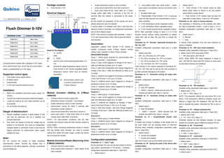
  • 1. Qubino The INNOVATIVE and SMALLEST Flush Dimmer 0-10V ORDERING CODE Z-WAVE FREQUENCY ZMNHVD1 868,4 MHz ZMNHVD2 921,4 MHz ZMNHVD3 908,4 MHz ZMNHVD4 869,0 MHz ZMNHVD5 916,0 MHz ZMNHVD8 865,2 MHz Universal dimmer module with a standard 0-10V output and a multi-function input, which may be a push button / switch, a potentiometer or 0-10V signal Supported control types  Push button (mono stable switch)  Bi stable switch  Potentiometer  0-10V input (requires external source) Installation  Before the installation disconnect power supply (12- 24VDC)  Connect the module according to electrical diagram.  Locate the antenna far from metal elements (as far as possible).  Do not shorten the antenna. Danger of electrocution!  Module installation requires a great degree of skill and may be performed only by a qualified and licensed electrician.  Even when the module is turned off, voltage may be present on its terminals. Any works on configuration changes related to connection mode or load must be always performed by disconnected power supply (disable the fuse). Note! Do not connect the module to loads exceeding recommended values. Connect the module only in accordance to the below diagrams. Improper connections may be dangerous. Package contents:  Flush Dimmer 0-10V Electrical diagram Notes for the diagram: + 12 - 24VDC - GND AO 0 - 10VDC I1 Input for push button/switch/potentiometer or 0- 10V TS Terminal for digital temperature sensor (only for Flush Dimmer 0-10V module compatible digital temperature sensor, which must be ordered separately). Module Inclusion (Adding to Z-Wave network)  Connect module to power supply (with temperature sensor connected - if purchased),  enable add/remove mode on main controller  auto-inclusion (works for about 5 seconds after connected to power supply) or  press service button S for more than 2 second or  press push button I1 three times within 3s (3 times change switch state within 3 seconds). NOTE1: For auto-inclusion procedure, first set main controller into inclusion mode and then connect module to power supply. NOTE2: When connecting temperature sensor to module that has already been included, you have to exclude module first. Switch off power supply, connect the sensor and re-include the module. Module Exclusion/Reset (Removing from Z-Wave network)  Connect module to power supply  bring module within maximum 1 meter (3feet) of the main controller,  enable add/remove mode on main controller,  press service button S for more than 6 second or  press push button I1 five times within 3s ( 5 times change switch state within 3 seconds) in the first 60 seconds after the module is connected to the power supply. By this function all parameters of the module are set to default values and own ID is deleted. If service button S is pressed more than 2 and less than 6second module is excluded, but configuration parameters are not set to default values. NOTE: If the module is included with parameter 1 value 3, 4 or 5 and module reset is done, wait at least 30s before next inclusion. Association Association enables Flush Dimmer 0-10V module to transfer commands inside Z-Wave network directly (without main controller) to other Z-Wave modules. Associated Groups: Group 1: Lifeline group (reserved for communication with the main controller), 1 node allowed. Group 2: basic on/off (triggered at change of the input I1 state and reflecting its state) up to 16 nodes Group 3: start level change/stop level change (triggered at change of the input I1 state and reflecting its state) up to 16 nodes Group 4: multilevel set (triggered at changes of state/value of the Flush Dimmer 0-10V) up to 16 nodes Group 5: multilevel sensor report (triggered at change of temperature sensor) up to 16 nodes. Group 6: multilevel sensor report (triggered at change of temperature sensor) up to 16 nodes. Endpoint 1: Group 1: Lifeline group, 0 nodes allowed. Group 2: basic on/off (triggered at change of the input I1 state and reflecting its state) up to 16 nodes Group 3: multilevel set (triggered at changes of state / value of the Flush Dimmer 0-10V) up to 16 nodes Group 4: start level change / stop level change (triggered at change of the input I1 state and reflecting its state) up to 16 nodes End point 2: Group 1: Lifeline group, 0 nodes allowed. Group 2: multilevel sensor report (triggered at change of temperature sensor) up to 16 nodes. End point 3: Group 1: Lifeline group, 0 nodes allowed. Group 2: multilevel sensor report (triggered at change of temperature sensor) up to 16 nodes. Configuration parameters Parameter no. 1 – Input 1 type By this parameter the user can set input based on device type (switch, potentiometer, 0-10V sensor,..). Available configuration parameters (data type is 1 Byte DEC):  default value 0  0 - mono-stable switch type (push button) – button quick press turns between previous set dimmer value and zero)  1 - Bi-stable switch type  2 - Potentiometer (Flush Dimmer 0-10V is using set value the last received from potentiometer or from z- wave controller)  3 - 0-10V Temperature sensor (regulated output)  4 - 0-10V Illumination sensor (regulated output)  5 - 0-10V General propose sensor (regulated output) NOTE: After parameter change to value 3, 4 or 5 first exclude module (without setting parameters to default value) then wait at least 30s and then re include the module! Parameter no. 10 - Activate / deactivate functions ALL ON / ALL OFF Available configuration parameters (data type is 2 Byte DEC):  default value 255  255 - ALL ON active, ALL OFF active.  0 - ALL ON is not active, ALL OFF is not active  1 - ALL ON is not active, ALL OFF active  2 - ALL ON active, ALL OFF is not active Flush Dimmer 0-10V module responds to commands ALL ON / ALL OFF that may be sent by the main controller or by other controller belonging to the system. Parameter no. 11 - Automatic turning off output after set time Available configuration parameters (data type is 2 Byte DEC):  default value 0  0 - Auto OFF disabled  1 - 32536 = 1second - 32536 seconds Auto OFF enabled with define time, step is 1 second. Parameter no. 12 - Automatic turning on output after set time Available configuration parameters (data type is 2 Byte DEC):  default value 0  0 - Auto ON disabled  1 - 32535 = 1second - 32535 seconds Auto ON enabled with define time, step is 1 second. Parameter no. 21 – Enable/Disable Double click function If Double click function is enabled, a fast double click on the push button will set dimming power at maximum dimming value. Available configuration parameters (data type is 1 Byte DEC):  default value 0  0 - Double click disabled  1 - Double click enabled Valid only if input is set as mono-stable (push button). Parameter no. 30 - Saving the state of the device after a power failure Available configuration parameters (data type is 1 Byte DEC):  default value 0  0 - Flush Dimmer 0-10V module saves its state before power failure (it returns to the last position saved before a power failure).  1 - Flush Dimmer 0-10V module does not save the state after a power failure, it returns to "off" position. Parameter no. 52 – Auto or manual selection This parameter is influencing on the software only when the value of parameter number 1 is set to value 3, 4 or 5. Available configuration parameters (data type is 1 Byte DEC):  default value 0  0 - Manual  1 - Auto In manual mode regulation (how the input influence on output) is disabled Parameter no. 53 - PID value inside deadband Available config. parameters (data type is 1 Byte DEC):  default value 0 (PID value equal ZERO)  1 - PID value set to LAST VALUE NOTE: When ZERO PID inside deadband is forced to zero. LASTVALUE means that PID remains on same level as was before entering into deadband Parameter no. 54 - PID deadband Available config. parameters (data type is 1 Byte DEC):  default value 1 (1%)  0 - 100 0 - 100%, step is 1% NOTE: This parameter defines the zone where PID is not active. If the temperature difference between actual and setpoint is bigger than PID deadband, then the PID will start to regulate the system, otherwise the PID is zero or fixed. Parameter no. 55 - Integral sampling time Available config. parameters (data type is 1 Byte DEC):  default value 5 (5s)  0 - 127 - 0s to 127s, step is 1s Parameter defines the time between samples. On each sample the controller capture difference between SP-act. Parameter no. 56 - P parameter Available config. parameters (data type is 2 Byte DEC):  default value 100  0 -1000 - P value, step is 1 Parameter no. 57 - I parameter Available config. parameters (data type is 2 Byte DEC):  default value 1  0 - 1000 - I value, step is 1 Parameter no. 58 - D parameter Available config. parameters (data type is2 Byte DEC):  default value 1 S Service button (used to add or remove module from the Z-Wave network).
  • 2.  0 - 1000 - D value, step is 1 Parameter no. 60 – Minimum dimming value Available configuration parameters (data type is 1 Byte DEC):  default value 1 = 1% (minimum dimming value)  1 - 98 = 1% - 98%, step is 1%. Minimum dimming values is set by entered value. NOTE: The minimum level may not be higher than the maximum level! 1% min. dimming value is defined by Z- Wave multilevel device class. Parameter no. 61 – Maximum dimming value Available configuration parameters (data type is 1 Byte DEC):  default value 99 = 99% (Maximum dimming value)  2 - 99 = 2% - 99%, step is 1%. Maximum dimming values is set by entered value. NOTE: The maximum level may not be lower than the minimum level! 99% max. dimming value is defined by Z- Wave multilevel device class. Parameter no. 65 – Dimming time (soft on/off) Set value means time of moving the Flush Dimmer 0-10V between min. and max. dimming values by short press of push button I1 or controlled through UI (BasicSet). Available config. parameters (data type is 2 Byte DEC):  default value 100 = 1s  1 - 255 = 100 mseconds - 2550 mseconds (2,55s), step is 100 mseconds Parameter no. 66 – Dimming time when key pressed Time of moving the Flush Dimmer 0-10V between min. and max dimming values by continues hold of push button I1 or associated device. Available configuration parameters (data type is 2 Byte DEC):  default value 3 = 3s  1 - 255 = 1 second - 255 seconds Parameter no. 67 – Ignore start level This parameter is used with association group 3. A receiving device SHOULD respect the start level if the Ignore Start Level bit is 0. A receiving device MUST ignore the start level if the Ignore Start Level bit is 1. Available configuration parameters (data type is 1 Byte DEC):  default value 0 (respect start level)  1 - (ignore start level) Parameter no. 68 – Dimming duration This parameter is used with association group 3. The Duration field MUST specify the time that the transition should take from the current value to the new target value. A supporting device SHOULD respect the specified Duration value. Available configuration parameters (data type is 1 Byte DEC):  default value 0 (dimming duration according to parameter 66)  1 – 127 (from 1 to 127 seconds) Parameter no. 110 – Temperature sensor offset settings Set value is added or subtracted to actual measured value by sensor. Available configuration parameters (data type is 2 Byte DEC):  default value 32536  32536 - offset is 0.0C  From 1 to 100 - value from 0.1 °C to 10.0 °C is added to actual measured temperature.  From 1001 to 1100 - value from -0.1 °C to -10.0 °C is subtracted to actual measured temperature. Parameter no. 120 – Digital temperature sensor reporting If digital temperature sensor is connected, module reports measured temperature on temperature change defined by this parameter. Available configuration parameters (data type is 1 Byte DEC):  default value 5 = 0,5°C change  0 - Reporting disabled  1 - 127 = 0,1°C - 12,7°C, step is 0,1°C Parameter no. 140 – Input I1 Sensor reporting If analogue sensor is connected, module reports measured value on change defined by this parameter. Available configuration parameters (data type is 2 Byte DEC):  default value 5 = 0,5 change  0 - Reporting disabled  1 - 10000 = 0,1 - 1000 step is 0,1 Parameter no. 141 Input I1 0-10V reporting threshold Parameter defines a value by which input voltage must change in order to be reported to the main controller. New value is calculated based on last reported value: Available configuration parameters (data type is 1 Byte DEC):  Default setting: 5 (0,5V)  1 - 100 - (0,1 - 10V) Parameter no. 143 – Minimum sensor range value Value that must correspond to minimum sensor range value. Valid only if parameter 1 is set to values 3, 4 or 5). Available configuration parameters (data type is 2 Byte DEC):  default value 0 = 0°C / 0Lux / 0%rh  0 - 10000 – value from 0 to 1000 (resolution 0,1)  10001 – 20000 – value from -0,1 to -1000 (resolution 0,1) NOTE: Minimum value must not be higher than maximum value! Parameter no. 144 – Maximum sensor range value Value that must correspond to maximum sensor range value. Valid only if parameter 1 is set to values 3, 4 or 5). Available configuration parameters (data type is 2 Byte DEC):  default value 1000 = 100°C / 100Lux / 100%rh  0 - 10000 – value from 0 to 1000 (resolution 0,1)  10001 – 20000 – value from -0,1 to -1000 (resolution 0,1) NOTE: Maximum value must not be lower than minimum value! Technical Specifications Power supply 12-24VDC Max. control voltage ratings -20 / +20VDC Control signal range 0-11VDC Max. sinking current 2mA Max. sourcing current 10mA Digital temperature sensor range (sensor must be ordered separately) 50 ~ +125°C Operation temperature -10 ~ +40°C Distance up to 30 m indoors (depending on building materials) Dimensions (WxHxD) (package) 41,8x36,8x15,4mm (79x52x22) Weight (Brutto with package) 28g (34g) Electricity consumption 0,5W Z-Wave Device Class: ZWAVEPLUS_INFO_REPORT_ROLE_TYPE_SLAVE_ALWAYS_0N GENERIC_TYPE_SWITCH_MULTILEVEL SPECIFIC_TYPE_POWER_SWITCH_MULTILEVEL Z-Wave Supported Command Classes: COMMAND_CLASS_ZWAVEPLUS_INFO_V2 COMMAND_CLASS_VERSION_V2 COMMAND_CLASS_MANUFACTURER_SPECIFIC_V2 COMMAND_CLASS_DEVICE_RESET_LOCALLY_V1 COMMAND_CLASS_POWERLEVEL_V1 COMMAND_CLASS_BASIC_V1 COMMAND_CLASS_SWITCH_ALL_V1 COMMAND_CLASS_SWITCH_BINARY_V1 COMMAND_CLASS_SWITCH_MULTILEVEL_V3 COMMAND_CLASS_SENSOR_MULTILEVE_V7 COMMAND_CLASS_MULTI_CHANNEL_V4 COMMAND_CLASS_ASSOCIATION_V2 COMMAND_CLASS_MULTI_CHANNEL_ASSOCIATION_V3 COMMAND_CLASS_ASSOCIATION_GRP_INFO_V2 COMMAND_CLASS_CONFIGURATION_V1 COMMAND_CLASS_MARK COMMAND_CLASS_BASIC_V1 COMMAND_CLASS_SWITCH_MULTILEVEL_V3 Endpoint 1 Device Class: ZWAVEPLUS_INFO_REPORT_ROLE_TYPE_SLAVE_ALWAYS_0N GENERIC_TYPE_SWITCH_MULTILEVEL SPE SPECIFIC_TYPE_POWER_SWITCH_MULTILEVEL Command Classes: COMMAND_CLASS_ZWAVEPLUS_INFO_V2, COMMAND_CLASS_VERSION_V2 COMMAND_CLASS_BASIC_V1 COMMAND_CLASS_SWITCH_ALL_V1 COMMAND_CLASS_SWITCH_BINARY_V1 COMMAND_CLASS_SENSOR_BINARY_V1 COMMAND_CLASS_SWITCH_MULTILEVEL_V3 COMMAND_CLASS_ASSOCIATION_2 COMMAND_CLASS_MULTI_CHANNEL_ASSOCIATION_V3 COMMAND_CLASS_ASSOCIATION_GRP_INFO_V2 COMMAND_CLASS_MARK COMMAND_CLASS_BASIC_V1 COMMAND_CLASS_SWITCH_MULTILEVEL_V3 Endpoint 2: Device Class: ZWAVEPLUS_INFO_REPORT_ROLE_TYPE_SLAVE_ALWAYS_0N GENERIC_TYPE_SENSOR_MULTILEVEL SPECIFIC_TYPE_ROUTING_SENSOR_MULTILEVEL Command Classes: COMMAND_CLASS_ZWAVEPLUS_INFO_V2 COMMAND_CLASS_VERSION_V2 COMMAND_CLASS_ASSOCIATION_V2 COMMAND_CLASS_MULTI_CHANNEL_ASSOCIATION_V3 COMMAND_CLASS_ASSOCIATION_GRP_INFO_V2 COMMAND_CLASS_SENSOR_MULTILEVEL_V7 Endpoint 3: Device Class: ZWAVEPLUS_INFO_REPORT_ROLE_TYPE_SLAVE_ALWAYS_0N GENERIC_TYPE_SENSOR_MULTILEVEL SPECIFIC_TYPE_ROUTING_SENSOR_MULTILEVEL Command Classes: COMMAND_CLASS_ZWAVEPLUS_INFO_V2 COMMAND_CLASS_VERSION_V2 COMMAND_CLASS_ASSOCIATION_V2 COMMAND_CLASS_MULTI_CHANNEL_ASSOCIATION_V3 COMMAND_CLASS_ASSOCIATION_GRP_INFO_V2 COMMAND_CLASS_SENSOR_MULTILEVEL_V7 NOTE: The above list is valid for the product with a temperature sensor connected to TS terminal. In case the sensor is not connected then following command class isn’t supported: COMMAND_CLASS_SENSOR_MULTILEVEL_V7 NOTE: The product supports the following COMMAND_CLASS_NOTIFICATION_V5 events: - Smoke Alarm v2 – Smoke detected, unknown location (0x02) - CO Alarm v2 – Carbon Monoxide detected, unknown location (0x02) - CO 2 Alarm – Carbon Dioxide detected, unknown location (0x02) - Heat Alarm v2 – Overheat detected, unknown location (0x02) - Water Alarm v2 – Water Leak detected, unknown location (0x02) - Home Security – Motion Detection, unknown location (0x08) This product can be included and operated in any Z-Wave network with other Z-Wave certified devices from any other manufacturers. All constantly powered nodes in the same network will act as repeaters regardless of the vendor in order to increase reliability of the network. Important disclaimer Z-Wave wireless communication is inherently not always 100% reliable, and as such, this product should not be used in situations in which life and/or valuables are solely dependent on its function. Warning! Do not dispose of electrical appliances as unsorted municipal waste, use separate collection facilities. Contact your local government for information regarding the collection systems available. If electrical appliances are disposed of in landfills or dumps, hazardous substances can leak into the groundwater and get into the food chain, damaging your health and well-being. When replacing old appliances with new once, the retailer is legally obligated to take back your old appliance for disposal at least for free of charge. This user manual is subject to change and improvement without notice. NOTE:User manual is valid for module with SW version S1 (SW version is part of P/N)! Example: P/N: ZMNHVDx HxS1Px Qubino Goap d.o.o. Nova Gorica Ulica Klementa Juga 007 5250 Solkan Slovenia E-mail: info@qubino.com Tel: +386 5 335 95 00 Web: www.qubino.com Date: 29.02.2016 Document: Qubino_Flush Dimmer 0-10V PLUS user manual_V1.0_eng