SlideShare une entreprise Scribd logo
1  sur  2
Télécharger pour lire hors ligne
EN
USER AND SAFETY GUIDE
Z-Wave™ smart switch with potential-free
contacts
READ BEFORE USE
This document contains important technical and safety informa-
tion about the Device, its safe use and installation.
⚠CAUTION! Before beginning the installation, please read carefully
and entirely this guide and any other documents accompanying the
device. Failure to follow the installation procedures could lead to
malfunction, danger to your health and life, violation of law or refusal
of legal and/or commercial guarantee (if any). Shelly Europe Ltd. is
not responsible for any loss or damage in case of incorrect installa-
tion or improper operation of this Device due to failure of following
the user and safety instructions in this guide.
TERMINOLOGY
Gateway – A Z-Wave™ gateway, also referred to as a Z-Wave™
controller, Z-Wave™ main controller, Z-Wave™ primary controller, or
Z-Wave™ hub, etc., is a device that serves as a central hub for a
Z-Wave™ smart home network. The term “gateway” is used in this
document.
S button - The Z-Wave™ Service button, which is located on
Z-Wave™ devices and is used for various functions such as adding
(inclusion), removing (exclusion), and resetting the device to its fac-
tory default settings. The term "S button" is used in this document.
Device – In this document, the term “Device” is used to refer to
the Wave 1 device.
ABOUT SHELLY QUBINO
Shelly Qubino is a line of innovative microprocessor-managed
devices, which allow remote control of electric circuits with a
smartphone, tablet, PC, or home automation system. They work on
Z-Wave™ wireless communication protocol, using a gateway. When
the gateway is connected to the internet, you can control Shelly
Qubino devices remotely from anywhere. Shelly Qubino devices can
be operated in any Z-Wave™ network with other Z-Wave™ certified
devices from other manufacturers. All mains operated nodes within
the network will act as repeaters regardless of vendor to increase
reliability of the network. Devices are designed to work with older
generations of Z-Wave™ devices and gateways.
ABOUT THE WAVE 1
The Wave 1 (Device) controls on/off function for one electrical
device, e.g., bulb, ceiling fan, IR heater, electrical locks, garage
doors, irrigation system, etc. The output contact is potential-free
(dry contact), so different power supply loads (up to 16 A) can be
connected to the Device. It is compatible with push-buttons and
switches (default).
ELECTRICAL DIAGRAM (110-240 V AC / 24-48 V DC /
12 V DC)
Refer to the schematics (Fig. 1-3) in this user guide.
INSTALLATION INSTRUCTIONS
The Device can control a various type of loads (e.g., bulbs) in one
electrical circuit up to 3.5 kW / 240 V AC. It can be retrofitted into
standard electrical wall boxes, behind power sockets and light
switches or other places with limited space.
⚠CAUTION! Danger of electrocution. Mounting/installation of the
Device to the power grid has to be performed with caution, by a
qualified electrician.
⚠WARNING! Danger of electrocution. Every change in the connec-
tions has to be done after ensuring there is no voltage present at
the Device terminals.
⚠CAUTION! Use the Device only with a power grid and applianc-
es that comply with all applicable regulations. A short circuit in the
power grid or any appliance connected to the Device may damage it.
⚠CAUTION! Do not connect the Device to appliances exceeding
the given max. load!
⚠CAUTION! Do not shorten the antenna.
⚠RECOMMENDATION: Place the antenna as far away as possible
from metal elements as they can cause signal interference.
⚠CAUTION! Connect the Device only in the way shown in these
instructions. Any other method could cause damage and/or injury.
⚠CAUTION! Do not install the Device where it can get wet.
⚠CAUTION! Do not use the Device if it has been damaged!
⚠CAUTION! Do not attempt to service or repair the Device yourself!
⚠RECOMMENDATION: Connect the Device using solid single-core
wires with increased insulation heat resistance not less than PVC
T105°C (221°F).
⚠CAUTION! Before starting the mounting/installation of the De-
vice, check that the breakers are turned off and there is no voltage
on their terminals. This can be done with a phase tester or multime-
ter. When you are sure that there is no voltage, you can proceed to
connecting the wires.
Connect the load circuit to the Device I and O terminals.
If you are using AC power supply for the Device, connect the Live
wire to the Device L terminal, and the Neutral wire to the N terminal
as shown on Fig. 1. Connect a switch or a push-button to the Device
SW terminal and the Live wire.
If you are using 24-48 V DC power supply (Fig. 2), connect the
+ wire to the + and the GND wire to the terminal of the Device.
If you are using stabilized 12 V DC power supply (Fig. 3), connect
the + wire to the 12V+ terminal, instead to the + terminal. Connect
the switch/push-button to the “SW” terminal and the GND wire.
⚠RECOMMENDATION: For inductive appliances that cause volt-
age spikes during switching on/off, such as electrical motors, fans,
vacuum cleaners and similar ones, RC snubber (0.1 µF / 100 Ω /
1/2 W / 600 VAC) should be connected parallel to the appliance.
⚠CAUTION! Do not allow children to play with the push-buttons/
switches connected to the Device. Keep the devices for remote
control of Shelly Qubino (mobile phones, tablets, PCs) away from
children.
Z-WAVE™ ADDING/REMOVING (INCLUSION/EXCLUSION)
SmartStart adding (inclusion):
SmartStart enabled products can be added into a Z-Wave™ network
by scanning the Z-Wave™ QR Code present on the Device with a
gateway providing SmartStart inclusion. No further action is re-
quired, and the SmartStart device will be added automatically with-
in 10 minutes of being switched on in the network vicinity.
1. With the gateway application scan the QR code on the Device
label and add the Security 2 (S2) Device Specific Key (DSK) to the
Provisioning List in the gateway.
2. Connect the Device to a power supply.
3. Check if the blue LED is blinking in Mode 1. If so, the Device is not
added to a Z-Wave™ network.
4. Adding will be initiated automatically within a few seconds after
connecting the Device to a power supply, and the Device will be
added to a Z-Wave™ network automatically.
5. The blue LED will be blinking in Mode 2 during the adding pro-
cess.
6. The load connected to O will be blinking 1s on/1s off/1s on/1s
off if the Device is successfully added to a Z-Wave™ network.
7. The green LED will be blinking in Mode 1 if the Device is success-
fully added to a Z-Wave™ network.
Adding (inclusion) with a switch/push-button:
1. Connect the Device to a power supply.
2. Check if the blue LED is blinking in Mode 1. If so, the Device is not
added to a Z-Wave™ network.
3. Enable add/remove mode on the gateway.
4. Toggle the switch/push-button connected to the SW terminal 3
times within 3 seconds (this procedure puts the Device in LEARN
MODE*). The Device must receive on/off signal 3 times, which
means pressing the push-button 3 times, or toggling the switch on
and off 3 times.
5. The blue LED will be blinking in Mode 2 during the adding pro-
cess.
6. The load connected to O will be blinking 1s on/1s off/1s on/1s
off if the Device is successfully added to a Z-Wave™ network.
7. The green LED will be blinking in Mode 1 if the Device is success-
fully added to a Z-Wave™ network.
*LEARN MODE state allows the Device to receive network informa-
tion from the gateway.
Adding (inclusion) with the S button:
1. Connect the Device to a power supply.
2. Check if the blue LED is blinking in Mode 1. If so, the Device is not
added to a Z-Wave™ network.
3. Enable add/remove mode on the gateway.
4. To enter the Setting mode, quickly press and hold the S button on
the Device until the LED turns Solid blue.
5. Quickly release and then press and hold (> 2 s) the S button on
the Device until the blue LED starts blinking in Mode 3. Releasing
the S button will start the LEARN MODE.
6. The blue LED will be blinking in Mode 2 during the adding pro-
cess.
7. The load connected to O will be blinking 1s on/1s off/1s on/1s
off if the Device is successfully added to a Z-Wave™ network.
8. The green LED will be blinking in Mode 1 if the Device is success-
fully added to a Z-Wave™ network.
Note! In Setting mode, the Device has a timeout of 10s before enter-
ing again into Normal mode.
Note! In case of Security 2 (S2) adding (inclusion), a dialog will ap-
pear asking you to enter the corresponding PIN code (5 underlined
digits) that are written on the DSK label on the side of the Device
and on the DSK label inserted in the packaging.
IMPORTANT: The PIN code must not be lost.
Removing (exclusion) with a switch/push-button:
1. Connect the Device to a power supply.
2. Check if the green LED is blinking in Mode 1. If so, the Device is
added to a Z-Wave™ network.
3. Enable add/remove mode on the gateway.
ORDERING CODE: QNSW-001X16XX
XX – Values define product version per region.
DECLARATION OF CONFORMITY
Hereby, Shelly Europe Ltd. (former Allterco Robotics EOOD) de-
clares that the radio equipment type Wave 1 is in compliance with
Directive 2014/53/EU, 2014/35/EU, 2014/30/EU, 2011/65/EU. The
full text of the EU declaration of conformity is available at the fol-
lowing internet address:
https://shelly.link/Wave1-DoC
MANUFACTURER:
Shelly Europe Ltd.
Address: 103 Cherni vrah Blvd., 1407 Sofia, Bulgaria
Tel.: +359 2 988 7435
E-mail: zwave-shelly@shelly.cloud
Support: https://support.shelly.cloud/
Web: https://www.shelly.com
Changes in the contact data are published by the Manufacturer at the
official website: https://www.shelly.com
DE
BENUTZER- UND SICHERHEITSHANDBUCH
Smarter Z-Wave™-Switch mit potenzialfreien
Kontakten
BITTE VOR GEBRAUCH DURCHLESEN
Dieses Dokument enthält wichtige technische und sicherheits-
technische Informationen über das Gerät und seine sichere Ver-
wendung und Installation.
⚠ACHTUNG! Bevor Sie mit der Installation beginnen, lesen Sie bit-
te die Begleitdokumentation sorgfältig und vollständig durch. Die
Nichtbeachtung der empfohlenen Verfahren kann zu Fehlfunktio-
nen, Lebensgefahr oder Gesetzesverstößen führen. Shelly Europe
Ltd. haftet nicht für Verluste oder Schäden im Falle einer falschen
Installation oder Bedienung dieses Geräts.
TERMINOLOGIE
Gateway - Ein Z-Wave™-Gateway, auch als Z-Wave™-Controller,
Z-Wave™-Hauptcontroller, Z-Wave™-Primärcontroller oder Z-Wave™-
Hub usw. bezeichnet, ist ein Gerät, das als zentraler Hub für ein
Z-Wave™-Smart-Home-Netzwerk dient. In diesem Dokument wird
der Begriff "Gateway" verwendet.
S-Taste - Die Z-Wave™ Service-Taste, die sich auf Z-Wave™-Geräten
befindet und für verschiedene Funktionen wie die Aufnahme
(Hinzufügen), der Ausschluss (Entfernen) und das Zurücksetzen
des Geräts auf die Werkseinstellungen verwendet wird. In diesem
Dokument wird der Begriff "S-Taste" verwendet.
Gerät - In diesem Dokument wird der Begriff "Gerät" für das Wave
1 Gerät verwendet.
ÜBER SHELLY QUBINO
Shelly Qubino ist eine Reihe innovativer, mikroprozessorgesteuert-
er Geräte, die die Fernsteuerung von Stromkreisen mit einem
Smartphone, Tablet, PC oder einem Hausautomatisierungssystem
ermöglichen. Sie arbeiten mit dem drahtlosen Z-Wave™-Kommu-
nikationsprotokoll unter Verwendung eines Gateways. Wenn das
Gateway mit dem Internet verbunden ist, können Sie die Shelly
Qubino Geräte von überall aus fernsteuern. Shelly Qubino Geräte
können in jedem Z-Wave™ Netzwerk mit anderen Z-Wave™ zertifi-
zierten Geräten anderer Hersteller betrieben werden. Alle netzbe-
triebenen Knotenpunkte innerhalb des Netzwerks werden unabhän-
gig vom Hersteller als Repeater fungieren, um die Zuverlässigkeit
des Netzwerks zu erhöhen. Die Geräte sind so konzipiert, dass
sie mit älteren Generationen von Z-Wave™-Geräten und Gateways
funktionieren.
ÜBER DAS WAVE 1
Das Wave 1 (Gerät) steuert die Ein- und Ausschaltfunktion für ein
elektrisches Gerät, z. B. Glühbirne, Deckenventilator, IR-Heizung,
elektrische Schlösser, Garagentore, Bewässerungsanlage, etc.
Der Ausgangskontakt ist potentialfrei (Trockenkontakt), so dass
verschiedene Stromversorgungslasten (bis zu 16 A) an das Gerät
angeschlossen werden können. Es ist kompatibel mit Drucktasten
und Schaltern (Standard).
ELEKTRISCHER SCHALTPLAN
(110–240 V AC / 24–48 V DC / 12 V DC)
SehenSiesichdieSchaltpläne(Abb.1–3)indiesemBenutzerhandbuchan.
INSTALLATIONSANLEITUNG
Das Gerät kann verschiedene Arten von Lasten (z. B. Glühbirnen)
in einem Stromkreis bis zu 3,5 kW / 240 V AC steuern. Es kann
in eine Standard-Unterputzkonsole nachgerüstet werden, hinter
Steckdosen und Lichtschaltern oder an anderen Orten mit begrenz-
tem Platz vorgesehen.
⚠VORSICHT! Gefahr eines Stromschlages. Die Montage/Installa-
tion des Geräts an das Stromnetz muss von einem qualifizierten
Elektriker mit Vorsicht durchgeführt werden!
⚠VORSICHT! Es besteht Stromschlaggefahr. Bei jeder Änderung
der Anschlüsse muss sichergestellt werden, dass an den Klemmen
des Geräts keine Spannung anliegt!
⚠VORSICHT! Verwenden Sie das Gerät nur mit einem Stromnetz
und Geräten, die allen geltenden Vorschriften entsprechen. Ein
Kurzschluss im Stromnetz oder in einem an das Gerät angeschlos-
senen Gerätes kann dieses beschädigen!
⚠VORSICHT! Schließen Sie das Gerät nicht an Geräte an, die die
angegebene Höchstlast überschreiten!
⚠VORSICHT! Kürzen Sie die Antenne nicht!
⚠EMPFEHLUNG: Stellen Sie die Antenne möglichst weit von
metallischen Gegenständen auf, da diese Signalstörungen verur-
sachen können.
⚠VORSICHT! Schließen Sie das Gerät nur auf die in dieser Anlei-
tung beschriebene Weise an. Jede andere Methode kann zu Schä-
den und/oder Verletzungen führen!
⚠VORSICHT! Installieren Sie das Gerät nicht an einem Ort, an dem
es nass werden kann!
⚠VORSICHT! Verwenden Sie das Gerät nicht, wenn es beschädigt ist!
⚠VORSICHT! Versuchen Sie nicht, das Gerät selbst zu warten
oder zu reparieren!
⚠EMPFEHLUNG: Schließen Sie das Gerät mit massiven einadri-
gen Kabeln mit erhöhter Isolationswärmebeständigkeit von min-
destens PVC T105°C (221°F) an!
⚠VORSICHT! Bevor Sie mit der Installation/Montage des Geräts
beginnen, prüfen Sie, ob die Leitungsschutzschalter (Sicherungen)
ausgeschaltet sind und keine Spannung an den Klemmen anliegt.
Dies kann mit einem Phasenprüfer oder Multimeter erfolgen. Wenn
Sie sicher sind, dass keine Spannung anliegt, können Sie mit dem
Anschluss der Kabel fortfahren!
Verbinden Sie den Lastkreis mit den Klemmen I und O.
Wenn Sie das Gerät mit Wechselstrom versorgen, verbinden Sie
die Phase mit der L-Klemme des Geräts und den Neutralleiter mit
der N-Klemme, wie in Abb. 1 dargestellt. Verbinden Sie einen Schal-
ter/Druckknopf mit der Klemme SW und der Phase.
Wenn Sie eine 24-48 V Gleichstromversorgung verwenden (Abb.
2), verbinden Sie +-Kabel mit der +-Klemme und GND mit der
-Klemme des Geräts.
Wenn Sie eine konstante 12 V Gleichstromversorgung verwenden
(Abb. 3), verbinden Sie das +-Kabel mit der 12V+-Klemme und GND
mit der -Klemme des Geräts. Verbinden Sie den Schalter/Druck-
knopf mit der SW-Klemme und dem GND-Kabel.
⚠EMPFEHLUNG: Bei induktiven Geräten, die beim Ein- und Aus-
schalten Spannungsspitzen verursachen, wie z. B. Elektromotoren,
Ventilatoren, Staubsauger und ähnliche, sollte ein RC-Snubber (0,1 µF
/ 100 Ω / 1/2 W / 600 VAC) parallel zum Gerät angeschlossen werden.
⚠VORSICHT! Erlauben Sie Kindern nicht, mit den an das Gerät
angeschlossenen Druckknopf /Schaltern zu spielen. Halten Sie die
Geräte zur Fernsteuerung des Shelly Qubino (z.B.: Mobiltelefone,
Tablets, PCs) von Kindern fern.
Z-WAVE™ HINZUFÜGEN/ENTFERNEN (AUFNAHME/
AUSSCHLUSS)
Hinzufügen (Aufnahme) von SmartStart:
SmartStart-fähige Produkte können in ein Z-Wave™-Netzwerk
aufgenommen werden, indem der Z-Wave™ QR-Code auf dem
Gerät mit einem Gateway gescannt wird, das die SmartStart-Ein-
bindung ermöglicht. Es sind keine weiteren Schritte erforderlich,
und das SmartStart-Gerät wird innerhalb von 10 Minuten nach dem
Einschalten automatisch in der Nähe des Netzwerks hinzugefügt.
1. Scannen Sie mit der Gateway-Anwendung den QR-Code auf dem
Geräteetikett und fügen Sie den Security 2 (S2) Device Specific Key
(DSK) zur Provisioning List im Gateway hinzu.
2. Schließen Sie das Gerät an eine Stromversorgung an.
3. Prüfen Sie, ob die blaue LED in Modus 1 blinkt. Ist dies der Fall,
wird das Gerät nicht in ein Z-Wave™-Netzwerk hinzugefügt.
4. Die Aufnahme (Hinzufügen) wird automatisch innerhalb weniger
Sekunden nach dem Anschluss des Geräts an die Stromversorgung
eingeleitet und das Gerät wird automatisch in das Z-Wave™-Netzw-
erk aufgenommen.
5. Die blaue LED blinkt im Modus 2 während des Aufnahmevor-
gangs (Hinzufügen).
6. Die an O angeschlossene Last blinkt 1 s Ein/1 s Aus/1 s Ein/1 s
Aus, wenn das Gerät erfolgreich in ein Z-Wave™-Netzwerk hinzuge-
fügt wurde.
7. Die grüne LED blinkt im Modus 1, wenn das Gerät erfolgreich zu
einem Z-Wave™-Netzwerk hinzugefügt wurde.
Hinzufügen (Aufnahme) mit einem Schalter/Druckknopf:
1. Schließen Sie das Gerät an eine Stromversorgung an.
2. Prüfen Sie, ob die blaue LED in Modus 1 blinkt. Ist dies der Fall,
wird das Gerät nicht in ein Z-Wave™-Netzwerk hinzugefügt.
3. Aktivieren Sie den Hinzufügen/Entfernen-Modus auf dem Gateway.
4. Schalten Sie den Schalter/Druckknopf, der mit der SW-Klemme
verbunden ist, 3 Mal innerhalb von 3 Sekunden um (dieser Vorgang
versetzt das Gerät in den LEARN MODE*). Das Gerät muss 3 Mal
ein Ein/Aus-Signal empfangen, d. h. 3 Mal den Druckknopf drücken
oder den Schalter 3 Mal ein- und ausschalten.
5. Die blaue LED blinkt im Modus 2 während des Aufnahmevor-
UNTERSTÜTZTE LASTTYPEN
• Kapazitiv (Kondensatorbatterien, elektronische Geräte, Motor-
startkondensatoren)
• Induktiv mit RC Snubber (LED-Lichttreiber, Transformatoren, Ven-
tilatoren, Kühlschränke, Klimageräte)
SPEZIFIKATION
Energieversorgung 110-240 V AC / 24-48 V DC /
12 V DC ± 10%
Stromverbrauch < 0.3 W
Max. Schaltspannung Wechsel-
strom AC
240 V
Max. Schaltstrom Wechsel-
strom AC
16 A
Max. Schaltspannung Gleich-
strom DC
30 V
Max. Schaltstrom Gleichstrom
DC
10 A
Überhitzungsschutz Ja
Entfernung Bis zu 40 m in Innenräumen
(131 ft.) (abhängig von den
örtlichen Gegebenheiten)
Z-Wave™ Repeater Ja
CPU Z-Wave™ S800
Z-Wave™ Frequenzbänder 868,4 MHz; 865,2 MHz; 869,0
MHz; 921,4 MHz; 908,4 MHz;
916 MHz; 919,8 MHz; 922,5
MHz; 919,7-921,7-923,7 MHz;
868,1 MHz; 920,9 MHz
Maximale übertragene
Funkfrequenzleistung in
Frequenzband(en)
< 25 mW
Größe (H × B × T) 37x42x16 ±0.5 mm /
1.46x1.65x0.63 ±0.02 in
Gewicht 26 g / 0.92 oz.
Montage Wandkonsole
Schraubklemmen max.
Drehmoment
0.4 Nm / 3.5 lbin
Querschnitt des Leiters 0.5 bis 1.5 mm² / 20 bis 16
AWG
Länge des abisolierten Leiters 5 bis 6 mm / 0.20 bis 0.24 in
Gehäusematerial Kunststoff
Farbe Blau
Umgebungstemperatur -20°C bis 40°C / -5°F bis 105°F
Luftfeuchtigkeit 30% bis 70% RH
Max. Höhe 2000 m / 6562 ft.
WICHTIG
Die Z-Wave™ drahtlose Kommunikation ist nicht immer 100 % ver-
lässlich. Dieses Modul soll nicht in Situationen verwendet werden,
in denen menschliches Leben oder Wertgegenstände allein von der
Funktion des Moduls abhängen. Falls das Modul von Ihrem Controller
nicht erkannt oder falsch angezeigt wird, müssen Sie eventuell den
Gerätetyp manuell eingeben und sicherstellen, dass ihr Gateway- Con-
troller Z-Wave Plus™ Helligkeitsregler unterstützt.
BESTELLCODES : QNSW-001X16XX
XX - Werte geben die Produktversion bezogen auf die Region an.
KONFORMITÄTSERKLÄRUNG
Hiermit erklärt Shelly Europe Ltd. (ehemals Allterco Robotics
EOOD), dass der Funkanlagentyp Wave 1 der Richtlinie 2014/53/EU,
2014/35/EU, 2014/30/EU, 2011/65/EU entspricht. Den vollständigen
Text der EU-Konformitätserklärung finden Sie unter folgender Inter-
netadresse:
https://shelly.link/Wave1-DoC
HERSTELLER:
Shelly Europe Ltd.
Adresse: 103 Cherni vrah Blvd., 1407 Sofia, Bulgarien
Tel.: +359 2 988 7435
E-mail: zwave-shelly@shelly.cloud
Kundensupport: https://support.shelly.cloud/
Offizielle Website: https://www.shelly.com
Änderungen der Kontaktdaten werden vom Hersteller auf dessen offi-
ziellen Website veröffentlicht: https://www.shelly.com
IT
GUIDA ALL'USO E ALLA SICUREZZA
Interruttore intelligente Z-Wave™ con contatti
a potenziale zero
LEGGERE PRIMA DELL'USO
Questo documento contiene importanti informazioni tecniche e di
sicurezza sul Dispositivo e sul suo uso e installazione in sicurezza.
⚠ATTENZIONE! Prima di iniziare l’installazione leggere attenta-
mente e completamente la documentazione allegata. La mancata
osservanza delle procedure consigliate potrebbe portare a malfun-
zionamenti, pericolo per la vita o violazione della legge. Shelly Eu-
rope Ltd. non è responsabile per eventuali perdite o danni in caso di
installazione o funzionamento errati di questo Dispositivo.
TERMINOLOGIA
Gateway – Un gateway Z-Wave™, anche chiamato controller
Z-Wave™, controller principale Z-Wave™, hub Z-Wave™, ecc., è un
dispositivo che funge da hub centrale per una rete domestica in-
telligente in tecnologia Z-Wave™. In questo documento si utilizzerà
semplicemente il termine "gateway".
Pulsante S – E’ il pulsante di Servizio Z-Wave™, che si trova sui
dispositivi Z-Wave™ e viene utilizzato per varie funzioni come per
l'inclusione (aggiunta), l'esclusione (rimozione) e il ripristino delle
impostazioni predefinite di fabbrica del dispositivo. In questo docu-
mento si utilizzerà semplicemente il termine "pulsante S".
Dispositivo - In questo documento, il termine "Dispositivo" viene
utilizzato per fare riferimento al dispositivo Wave 1.
A PROPOSITO DI SHELLY QUBINO
Shelly Qubino è una linea di dispositivi innovativi gestiti da micro-
processore, che consentono il controllo remoto dei circuiti elettrici
con smartphone, tablet, PC o sistema domotico. Funzionano su
protocollo di comunicazione wireless Z-Wave™, utilizzando un
gateway. Quando il gateway è connesso a Internet, puoi controllare
i dispositivi Shelly Qubino in remoto da qualsiasi luogo. I dispositivi
Shelly Qubino possono essere utilizzati in qualsiasi rete Z-Wave™
con altri dispositivi certificati Z-Wave™ di altri produttori. Tutti i nodi
gestiti dalla rete all'interno della rete fungeranno da ripetitori indip-
endentemente dal fornitore per aumentare l'affidabilità della rete. I
dispositivi sono progettati per funzionare con le generazioni prec-
edenti di dispositivi e gateway Z-Wave™.
A PROPOSITO DI WAVE 1
Il Wave 1 (Dispositivo) controlla la funzione on/off per un disposi-
tivo elettrico, ad es. lampadina, ventilatore da soffitto, riscaldatore
IR, serrature elettriche, porte del garage, sistema di irrigazione, ecc.
Il contatto di uscita è a potenziale zero (contatto pulito), quindi al
Dispositivo possono essere collegati diversi carichi di alimentazi-
one (fino a 16 A). È compatibile con pulsanti e interruttori (default).
SCHEMA ELETTRICO (110-240 V CA / 24-48 V CC /
12 V CC)
Fare riferimento agli schemi (Fig. 1-3) in questa guida per l'utente.
ISTRUZIONI PER L'INSTALLAZIONE
Il Dispositivo può controllare vari tipi di carichi (ad es. lampadine)
in un circuito elettrico fino a 3,5 kW / 240 V CA. Può essere adattato
a una console da incasso standard, dietro prese di corrente e inter-
ruttori della luce o in altri luoghi con spazio limitato.
⚠ATTENZIONE! Pericolo di folgorazione. Il montaggio/installa-
zione del Dispositivo alla rete elettrica deve essere eseguito con
cautela da un elettricista qualificato.
⚠ATTENZIONE! Pericolo di folgorazione. Ogni modifica dei colle-
gamenti deve essere effettuata dopo essersi assicurati che non ci
sia tensione sui terminali del Dispositivo.
⚠ATTENZIONE! Utilizzare il Dispositivo solo con una rete elettrica
e con apparecchi conformi a tutte le norme vigenti. Un cortocircuito
nella rete elettrica o in qualsiasi apparecchio collegato al Disposi-
tivo può danneggiarlo.
⚠ATTENZIONE! Non collegare il Dispositivo ad apparecchi che
superano il carico massimo indicato!
⚠ATTENZIONE! Non accorciare l'antenna.
⚠RACCOMANDAZIONE: Posizionare l'antenna il più lontano
possibile da elementi metallici in quanto essi potrebbero causare
interferenze di segnale.
⚠ATTENZIONE! Collegare il Dispositivo solo nel modo indicato in
queste istruzioni. Qualsiasi altro metodo potrebbe causare danni
e/o lesioni.
⚠ATTENZIONE! Non installare il Dispositivo in un luogo che possa
bagnarsi.
⚠ATTENZIONE! Non utilizzare il Dispositivo se è stato danneggiato!
⚠ATTENZIONE! Non tentare di riparare o riparare il Dispositivo
da soli!
⚠RACCOMANDAZIONE: Collegare il Dispositivo utilizzando cavi
unipolari solidi con una maggiore resistenza termica dell'isolamen-
to non inferiore a PVC T105°C (221°F).
⚠ATTENZIONE! Prima di iniziare l'installazione/montaggio del
Dispositivo, controllare che gli interruttori siano spenti e che non
ci sia tensione sui loro terminali. Questo può essere fatto con un
misuratore di fase o un multimetro. Quando siete sicuri che non c'è
tensione, potete procedere al collegamento dei cavi.
4. Toggle the switch/push-button connected to the SW terminal 3
times within 3 seconds (this procedure puts the Device in LEARN
MODE*). The Device must receive on/off signal 3 times, which
means pressing the push-button 3 times, or toggling the switch on
and off 3 times.
5. The blue LED will be blinking in Mode 2 during the removing
process.
6. The load connected to O will be blinking 1s on/1s off/1s on/1s
off if the Device is successfully removed from a Z-Wave™ network.
7. The blue LED will be blinking in Mode 1 if the Device is success-
fully removed from a Z-Wave™ network.
Removing (exclusion) with the S button:
1. Connect the Device to a power supply.
2. Check if the green LED is blinking in Mode 1. If so, the Device is
added to a Z-Wave™ network.
3. Enable add/remove mode on the gateway.
4. To enter the Setting mode, quickly press and hold the S button on
the Device until the LED turns Solid blue.
5. Quickly release and then press and hold (> 2s) the S button on the
Device until the blue LED starts blinking in Mode 3. Releasing the S
button will start the LEARN MODE.
6. The blue LED will be blinking in Mode 2 during the removing
process.
7. The load connected to O will be blinking 1s on/1s off/1s on/1s
off if the Device is successfully removed from a Z-Wave™ network.
8. The blue LED will be blinking in Mode 1 if the Device is success-
fully removed from a Z-Wave™ network.
Note! In Setting mode, the Device has a timeout of 10s before enter-
ing again into Normal mode.
FACTORY RESET
After Factory reset, all custom parameters and stored values (as-
sociations, routings, etc.) will return to their default state. HOME
ID and NODE ID assigned to the Device will be deleted. Use this
reset procedure only when the gateway is missing or otherwise
inoperable.
Factory reset with a switch/push-button:
Note! Factory reset with the switch/push-button is only possible with-
in the first minute after the Device is connected to a power supply.
1. Connect the Device to a power supply.
2. Toggle the switch/push-button connected to the SW terminal 5
times within 3 seconds. The Device must receive on/off signal 5
times, which means pressing the push-button 5 times, or toggling
the switch on and off 5 times.
3. During factory reset, the LED will turn solid green for about 1s,
then the blue and red LED will start blinking in Mode 3 for approx. 2s.
4. The blue LED will be blinking in Mode 1 if the Factory reset is
successful.
Factory reset with the S button:
Note! Factory reset with the S button is possible anytime.
1. To enter the Setting mode, quickly press and hold the S button on
the Device until the LED turns Solid blue.
2. Press the S button multiple times until the LED turns Solid red.
3. Press and hold (> 2s) S button on the Device until the red LED
starts blinking in Mode 3. Releasing the S button will start the fac-
tory reset.
4. During factory reset, the LED will turn solid green for about 1s,
then the blue and red LED will start blinking in Mode 3 for approx.
2s.
5. The blue LED will be blinking in Mode 1 if the Factory reset is
successful.
NOTE: For more information about this Device refer to the Extended
User Guide available at: https://kb.shelly.cloud/
LED SIGNALIZATION
LED blinking modes
Mode 1 0,5s On/2s Off
Mode 2 0,5s On/0,5s Off
Mode 3 0,1s On/0,1s Off
Mode 4 (1x to 6x - 0,2s On/0,2s Off) +
2s Off
Normal mode Colour LED mode
Removed/Excluded Blue Mode 1
Added/Included Green Mode 1
Setting mode (with S button)
Adding/Removing (Inclusion/Exclusion)
menu selected
Blue Solid
Adding/Removing (Inclusion/Exclusion)
menu - while pressing S button -
Adding/Removing (Inclusion/Exclusion)
process selected
Blue Mode 3
Factory reset menu selected Red Solid
Factory reset - while pressing S button -
Factory reset process selected
Red Mode 3
“Setting in progress” mode
Factory reset and reboot B l u e /
R e d /
Green
**
Adding/Removing (Inclusion/Exclusion) Blue Mode 2
OTA firmware updating B l u e /
Red
Mode 2
Alarm mode
Overheat detected Red Mode4(2x)
** The LED will turn solid green for about 1s, then the blue and red
LED will start blinking in Mode 3 for approx. 2s.
LED will turn off 30 minutes after the power cycle. Every time you press
on the S button, the LED will turn on for 30 minutes. If alarm is active,
LED will not turn off.
OPERATIONAL INSTRUCTIONS
If the SW is configured as a switch (default), each toggle of the
switch will change the output O state to the opposite state - on,
off, on, etc.
If the SW is configured as a push-button in the Device settings,
each press of the push-button will change the output O state to
the opposite state - on, off, on, etc.
SUPPORTED LOAD TYPES
• Resistive (incandescent bulbs, heating devices)
• Capacitive (capacitor banks, electronic equipment, motor start
capacitors)
• Inductive with RC Snubber (LED light drivers, transformers, fans,
refrigerators, air-conditioners)
SPECIFICATIONS
Power supply 110-240 V AC / 24-48 V DC /
12 V DC ± 10%
Power consumption < 0.3 W
Max. switching voltage AC 240 V
Max. switching current AC 16 A
Max. switching voltage DC 30 V
Max. switching current DC 10 A
Overheating protection Yes
Distance Up to 40 m indoors (131 ft.)
(depends on local condition)
Z-Wave™ repeater Yes
CPU Z-Wave™ S800
Z-Wave™ frequency bands 868,4 MHz; 865,2 MHz; 869,0
MHz; 921,4 MHz; 908,4 MHz;
916 MHz; 919,8 MHz; 922,5
MHz; 919,7-921,7-923,7 MHz;
868,1 MHz; 920,9 MHz
Maximum radio frequency
power transmitted in frequency
band(s)
< 25 mW
Size (H x W x D) 37x42x16 ±0.5 mm /
1.46x1.65x0.63 ±0.02 in
Weight 26 g / 0.92 oz.
Mounting Wall console
Screw terminals max. torque 0.4 Nm / 3.5 lbin
Conductor cross section 0.5 to 1.5 mm² / 20 to 16 AWG
Conductor stripped length 5 to 6 mm / 0.20 to 0.24 in
Shell material Plastic
Color Blue
Ambient temperature -20°C to 40°C / -5°F to 105°F
Humidity 30% to 70% RH
Max. altitude 2000 m / 6562 ft.
IMPORTANT DISCLAIMER
Z-Wave™ wireless communication may not always be 100% reliable.
This Device should not be used in situations in which life and/or va-
luables are solely dependent on its functioning. If the Device is not
recognized by your gateway or appears incorrectly, you may need to
change the Device type manually and ensure that your gateway sup-
ports Z-Wave Plus™ multi-level devices.
gangs (Hinzufügen).
6. Die an O angeschlossene Last blinkt 1 s Ein/1 s Aus/1 s Ein/1 s
Aus, wenn das Gerät erfolgreich in ein Z-Wave™-Netzwerk hinzuge-
fügt wurde.
7. Die grüne LED blinkt im Modus 1, wenn das Gerät erfolgreich zu
einem Z-Wave™-Netzwerk hinzugefügt wurde.
*Der Status LEARN MODE ermöglicht es dem Gerät, Netzwerkinfor-
mationen vom Gateway zu empfangen.
Hinzufügen (Aufnahme) mit der S-Taste:
1. Schließen Sie das Gerät an eine Stromversorgung an.
2. Prüfen Sie, ob die blaue LED in Modus 1 blinkt. Ist dies der Fall,
wird das Gerät nicht in ein Z-Wave™-Netzwerk hinzugefügt.
3. Aktivieren Sie den Hinzufügen/Entfernen-Modus auf dem Gate-
way.
4. Um den Einstellungsmodus aufzurufen, halten Sie die S-Taste
Sauf dem Gerät kurz gedrückt, bis die LED dauerhaft blau leuchtet.
5. Lassen Sie die S-Taste am Gerät schnell los und halten Sie sie
dann gedrückt (> 2 s), bis die blaue LED im Modus 3 zu blinken
beginnt. Wenn Sie die S-Taste loslassen, wird der LEARN MODE
gestartet.
6. Die blaue LED blinkt im Modus 2 während des Aufnahmevor-
gangs (Hinzufügen).
7. Die an O angeschlossene Last blinkt 1 s Ein/1 s Aus/1 s Ein/1 s
Aus, wenn das Gerät erfolgreich in ein Z-Wave™-Netzwerk aufge-
nommen wurde.
8. Die grüne LED blinkt im Modus 1, wenn das Gerät erfolgreich zu
einem Z-Wave™-Netzwerk hinzugefügt wurde.
Achtung! Im Einstellungsmodus hat das Gerät einen Timeout von
10s, bevor es wieder in den Normalmodus wechselt.
Achtung! Im Falle der Aufnahme (Hinzufügen) von Security 2 (S2)
erscheint ein Dialog, in dem Sie aufgefordert werden, die entsprech-
ende PIN-Code (5 unterstrichene Ziffern) einzugeben, die auf dem
DSK-Etikett an der Seite des Geräts und auf dem DSK-Etikett in der
Verpackung angegeben ist.
WICHTIG: Der PIN-Code darf nicht verloren gehen.
Entfernen (Ausschluss) mit dem Schalter/Druckknopf:
1. Schließen Sie das Gerät an eine Stromversorgung an.
2. Prüfen Sie, ob die grüne LED in Modus 1 blinkt. Wenn ja, wird das
Gerät zu einem Z-Wave™-Netzwerk hinzugefügt.
3. Aktivieren Sie den Hinzufügen/Entfernen-Modus auf dem Gate-
way.
4. Schalten Sie den Schalter/Druckknopf, der mit der SW-Klemme
verbunden ist, 3 Mal innerhalb von 3 Sekunden um (dieser Vorgang
versetzt das Gerät in den LEARN MODE*). Das Gerät muss 3 Mal
ein Ein/Aus-Signal empfangen, d. h. 3 Mal den Druckknopf drücken
oder den Schalter 3 Mal ein- und ausschalten.
5. Die blaue LED blinkt im Modus 2 während des Ausschlussver-
fahrens (Entfernen).
6. Die an O angeschlossene Last O blinkt 1 s Ein/1 s Aus/1 s Ein/1 s
Aus, wenn das Gerät erfolgreich aus einem Z-Wave™-Netzwerk en-
tfernt wurde.
7. Die blaue LED blinkt im Modus 1, wenn das Gerät erfolgreich aus
einem Z-Wave™-Netzwerk entfernt wurde.
Entfernen (Ausschluss) mit der S-Taste:
1. Schließen Sie das Gerät an eine Stromversorgung an.
2. Prüfen Sie, ob die grüne LED in Modus 1 blinkt. Wenn ja, wird das
Gerät zu einem Z-Wave™-Netzwerk hinzugefügt.
3. Aktivieren Sie den Hinzufügen/Entfernen-Modus auf dem Gate-
way.
4. Um den Einstellungsmodus aufzurufen, halten Sie die S-Taste
auf dem Gerät kurz gedrückt, bis die LED dauerhaft blau leuchtet.
5. Lassen Sie die S-Taste am Gerät schnell los und halten Sie sie
dann gedrückt (> 2 s), bis die blaue LED im Modus 3 zu blinken
beginnt. Wenn Sie die S-Taste loslassen, wird der LEARN MODE
gestartet.
6. Die blaue LED blinkt im Modus 2 während des Ausschlussver-
fahrens (Entfernen).
7. Die an O angeschlossene Last O blinkt 1 s Ein/1 s Aus/1 s Ein/1
s Aus, wenn das Gerät erfolgreich aus einem Z-Wave™-Netzwerk
entfernt wurde.
8. Die blaue LED blinkt im Modus 1, wenn das Gerät erfolgreich aus
einem Z-Wave™-Netzwerk entfernt wurde.
Achtung! Im Einstellungsmodus hat das Gerät einen Timeout von
10s, bevor es wieder in den Normalmodus wechselt.
ZURÜCKSETZEN AUF DIE WERKSEINSTELLUNGEN
Nach dem Zurücksetzen auf die Werkseinstellungen werden alle
benutzerdefinierten Parameter und gespeicherten Werte (Zuord-
nungen, Routings usw.) auf den Standardzustand zurückgesetzt.
HOME ID und NODE ID, die dem Gerät zugewiesen sind, werden
gelöscht. Verwenden Sie dieses Verfahren zum Zurücksetzen nur,
wenn das Gateway fehlt oder aus anderen Gründen nicht funktions-
fähig ist.
Zurücksetzen auf die Werkseinstellungen mit dem
Schalter/Druckknopf:
Achtung! Das Zurücksetzen auf die Werkseinstellungen mit dem
Schalter/Druckknopf ist nur innerhalb der ersten Minute möglich,
nachdem das Gerät an eine Stromversorgung angeschlossen
wurde.
1. Schließen Sie das Gerät an eine Stromversorgung an.
2. Schalten Sie den Schalter/Druckknopf, der mit dem SW-An-
schluss verbunden ist, 5 Mal innerhalb von 3 Sekunden um. Das
Gerät muss 5 Mal ein Ein/Aus-Signal empfangen, d. h. 5 Mal den
Taster drücken oder 5 Mal den Schalter ein- und ausschalten.
3. Während des Zurücksetzens auf die Werkseinstellungen leuchtet
die LED für ca. 1 s durchgehend grün, dann beginnen die blaue und
rote LED im Modus 3 für ca. 2 s zu blinken.
4. Die blaue LED blinkt im Modus 1, wenn das Zurücksetzen auf die
Werkseinstellungen erfolgreich war.
Zurücksetzen auf die Werkseinstellungen mit der
S-Taste:
Achtung! Das Zurücksetzen auf die Werkseinstellungen mit der
S-Taste ist jederzeit möglich.
1. Um den Einstellungsmodus aufzurufen, halten Sie die S-Taste
auf dem Gerät kurz gedrückt, bis die LED blau leuchtet.
2. Drücken Sie die S-Taste mehrmals, bis die LED dauerhaft rot leuchtet.
3. Halten Sie (> 2 s) die S-Taste am Gerät gedrückt, bis die rote LED
im Modus 3 zu blinken beginnt. Wenn Sie die S-Taste loslassen,
wird der Werksreset gestartet.
4. Während des Zurücksetzens auf die Werkseinstellungen leuchtet
die LED für ca. 1 s durchgehend grün, dann beginnen die blaue und
rote LED im Modus 3 für ca. 2 s zu blinken.
5. Die blaue LED blinkt im Modus 1, wenn das Zurücksetzen auf die
Werkseinstellungen erfolgreich war.
HINWEIS: Weitere Informationen zu diesem Gerät find-
en Sie im Erweiterten Benutzerhandbuch auf der Website:
https://kb.shelly.cloud/
LED-SIGNALISIERUNG
LED-Blinkmodus
Modus 1 0,5 s Ein/2 s Aus
Modus 2 0,5 s Ein/0,5 s Aus
Modus 3 0,1 s Ein/0,1 s Aus
Modus 4 (1x bis 6x - 0,2 s Ein/0,2 s Aus)
+ 2 s Aus
Normalmodus Farbe LED-Modus
Entfernt/Ausgeschlossen Blau Modus 1
Hinzugefügt/Aufgenommen Grün Modus 1
Einstellungsmodus (mit der S-Taste)
Menü Hinzufügen/Entfernen (Auf-
nahme/Ausschluss) ausgewählt
Blau Dauerhaft
Menü Hinzufügen/Entfernen (Aufnahme/
Ausschluss) - bei gedrückter S-Taste -
Prozess Hinzufügen/Entfernen (Aufnahme/
Ausschluss) ausgewählt
Blau Modus 3
Menü Zurücksetzen auf die Werksein-
stellungen ausgewählt
Rot Dauerhaft
Zurücksetzen auf die Werkseinstellun-
gen - bei gedrückter S-Taste - Zurückset-
zen auf die Werkseinstellungen Prozess
ausgewählt
Rot Modus 3
Modus "Einstellung im Gange"
Zurücksetzen auf die Werkseinstellun-
gen und Neustart
B l a u /
R o t /
Grün
**
Hinzufügen/Entfernen (Aufnahme/
Ausschluss)
Blau Modus 2
Firmware-Aktualisierung OTA B l a u /
Rot
Modus 2
Alarmmodus
Überhitzung erkannt Rot Modus4(2x)
** Die LED leuchtet für ca. 1 s durchgehend grün, dann beginnen die
blaue und rote LED im Modus 3 für ca. 2 s zu blinken.
Die LED schaltet sich 30 Minuten nach dem Stromzyklus aus. Jedes
Mal, wenn Sie die S-Taste drücken, leuchtet die LED 30 Minuten lang.
Wenn der Alarm aktiv ist, schaltet sich die LED nicht aus.
BETRIEBLICHE ANWEISUNGEN
Wenn der SW als Schalter konfiguriert ist ("Standard"), ändert sich der
Zustand des Ausgangs O bei jeder Schaltung des Schalters in den ent-
gegengesetzten Zustand - ein, aus, ein...
Wenn der SW in den Geräteeinstellungen als Druckknopf konfiguriert ist,
ändert jeder Druck auf den Druckknopf den Zustand des Ausgangs O in
den entgegengesetzten Zustand - ein, aus, ein...
Collegare il circuito di carico ai terminali I e O del Dispositivo.
Se si utilizza l'alimentazione CA per il Dispositivo, collegare il filo
Sotto tensione al terminale L del Dispositivo e il filo Neutro al ter-
minale N come mostrato in fig. 1. Collegare un interruttore o un
pulsante al terminale SW del Dispositivo e al filo Sotto tensione.
Se si utilizza un'alimentazione 24-48 V CC (fig. 2), collegare il filo +
al + e il filo GND ai terminali del Dispositivo.
Se si utilizza un alimentatore stabilizzato a 12V CC (fig. 3), collegare
il filo + al terminale 12V+, anziché al morsetto +. Collegare l'interrut-
tore/pulsante al terminale SW e al filo GND.
⚠RACCOMANDAZIONE: Per gli apparecchi induttivi che causano
picchi di tensione durante l'accensione e lo spegnimento, come
motori elettrici, ventilatori, aspirapolvere e simili, è necessario col-
legare in parallelo all'apparecchio uno snubber RC (0,1µF / 100 Ω /
1/2 W / 600 VAC).
⚠ATTENZIONE! Non permettere ai bambini di giocare con i pul-
santi/interruttori collegati al Dispositivo. Tenere i dispositivi per
il controllo remoto di Shelly Qubino (telefoni cellulari, tablet, PC)
lontano dai bambini.
AGGIUNTA/RIMOZIONE (INCLUSIONE/ESCLUSIONE) Z-WAVE™
Aggiunta (inclusione) SmartStart:
Se il tuo gateway fornisce l'inclusione SmartStart, i prodotti abilitati
SmartStart possono essere aggiunti a una rete Z-Wave™ scansion-
ando il codice QR Z-Wave™ presente sul Dispositivo. Non sono
necessarie ulteriori azioni e il dispositivo SmartStart verrà aggiunto
automaticamente entro 10 minuti dall'accensione nelle vicinanze
della rete.
1. Utilizzando l'applicazione del gateway, scansionare il codice QR
sull'etichetta del Dispositivo e aggiungere la Device Specific Key
(DSK) Security 2 (S2) all'elenco di provisioning del gateway.
2. Collegare il Dispositivo a un alimentazione.
3. Controllare se il LED blu lampeggia in modalità 1. In tal caso, il
Dispositivo non è ancora stato aggiunto a una rete Z-Wave™.
4. L'inclusione (aggiunta) verrà avviata automaticamente entro po-
chi secondi dal collegamento del Dispositivo a un alimentazione e
il Dispositivo verrà aggiunto automaticamente alla rete Z-Wave™.
5. Il LED blu lampeggerà in modalità 2 durante il processo di inclu-
sione (aggiunta).
6. Il carico collegato a O lampeggerà per 1s acceso/1s spento/1s
acceso/1s spento quando il Dispositivo risulterà aggiunto corretta-
mente a una rete Z-Wave™.
7. Il LED verde lampeggerà in modalità 1 se il Dispositivo viene ag-
giunto correttamente a una rete Z-Wave™.
Aggiunta (inclusione) con interruttore/pulsante:
1. Collegare il Dispositivo a un alimentazione.
2. Controllare se il LED blu lampeggia in modalità 1. In tal caso, il
Dispositivo non è ancora stato aggiunto a una rete Z-Wave™.
3. Abilitare la modalità aggiungi/rimuovi sul gateway.
4. Azionare 3 volte nell'arco di 3 secondi l'interruttore/pulsante
collegato al terminale SW (questa procedura pone il Dispositivo in
LEARN MODE*). Il Dispositivo deve ricevere il segnale di accensi-
one/spegnimento 3 volte, il che significa premere il pulsante per 3
volte o accendere e spegnere l'interruttore per 3 volte.
5. Il LED blu lampeggerà in modalità 2 durante il processo di inclu-
sione (aggiunta).
6. Il carico collegato a O lampeggerà per 1s acceso/1s spento/1s
acceso/1s spento quando il Dispositivo risulterà aggiunto corretta-
mente a una rete Z-Wave™
7. Il LED verde lampeggerà in modalità 1 se il Dispositivo viene ag-
giunto correttamente a una rete Z-Wave™.
*Lo stato LEARN MODE consente al Dispositivo di ricevere infor-
mazioni di rete dal gateway.
Aggiunta (inclusione) con il pulsante S:
1. Collegare il Dispositivo a un alimentazione.
2. Controllare se il LED blu lampeggia in modalità 1. In tal caso, il
Dispositivo non è ancora stato aggiunto a una rete Z-Wave™.
3. Abilitare la modalità aggiungi/rimuovi sul gateway.
4. Per accedere alla modalità di impostazione, premere rapida-
mente e tenere premuto il pulsante S sul Dispositivo finché il LED
non diventa blu fisso.
5. Rilasciare rapidamente e quindi tenere premuto (> 2s) il pulsante
S sul Dispositivo fino a quando il LED blu inizia a lampeggiare in
modalità 3. Rilasciando il pulsante S si avvia la LEARN MODE.
6. Il LED blu lampeggerà in modalità 2 durante il processo di inclu-
sione (aggiunta).
7. Il carico collegato a O lampeggerà per 1s acceso/1s spento/1s
acceso/1s spento quando il Dispositivo risulterà aggiunto corretta-
mente a una rete Z-Wave™.
8.Il LED verde lampeggerà in modalità 1 se il Dispositivo viene aggi-
unto correttamente a una rete Z-Wave™.
Nota! In modalità Impostazioni il Dispositivo ha un timeout di 10s
prima di entrare nuovamente in modalità Normale.
Nota! In caso di aggiunta (inclusione) Security 2 (S2), apparirà una
finestra di dialogo che chiede di inserire il codice PIN corrisponden-
te (5 cifre sottolineate) che è scritto sull'etichetta DSK apposta sul
lato del Dispositivo e sull'etichetta DSK inserita nella confezione..
IMPORTANTE: il codice PIN non deve essere perso.
Rimozione (esclusione) con interruttore/pulsante:
1. Collegare il Dispositivo a un alimentazione.
2. Verificare se il LED verde lampeggia in modalità 1. In tal caso, il
Dispositivo è aggiunto a una rete Z-Wave™.
3. Abilitare la modalità aggiungi/rimuovi sul gateway.
4. Azionare 3 volte nell'arco di 3 secondi l'interruttore/pulsante
collegato al terminale SW (questa procedura pone il Dispositivo in
LEARN MODE*). Il Dispositivo deve ricevere il segnale di accensi-
one/spegnimento 3 volte, il che significa premere il pulsante per 3
volte o accendere e spegnere l'interruttore per 3 volte.
5. Il LED blu lampeggerà in modalità 2 durante il processo di esclu-
sione (rimozione).
6. Il carico collegato a O lampeggerà per 1s acceso/1s spento/1s
acceso/1s spento quando il dispositivo risulterà rimosso con suc-
cesso da una rete Z-Wave™.
7. Il LED blu lampeggerà in modalità 1 se il Dispositivo viene rimos-
so con successo da una rete Z-Wave™.
Rimozione (esclusione) con il pulsante S:
1. Collegare il Dispositivo a un alimentazione.
2. Verificare se il LED verde lampeggia in modalità 1. In tal caso, il
Dispositivo è aggiunto a una rete Z-Wave™.
3. Abilitare la modalità aggiungi/rimuovi sul gateway.
4. Per accedere alla modalità di impostazione, premere rapida-
mente e tenere premuto il pulsante S sul Dispositivo finché il LED
non diventa blu fisso.
5. Rilasciare rapidamente e quindi tenere premuto (> 2s) il pulsante
S sul Dispositivo fino a quando il LED blu inizia a lampeggiare in
modalità 3. Rilasciando il pulsante S si avvia la LEARN MODE.
6. Il LED blu lampeggerà in modalità 2 durante il processo di esclu-
sione (rimozione).
7. Il carico collegato a O lampeggerà per 1s acceso/1s spento/1s
acceso/1s spento quando il Dispositivo risulterà rimosso con suc-
cesso da una rete Z-Wave™.
8. Il LED blu lampeggerà in modalità 1 se il Dispositivo viene rimos-
so con successo da una rete Z-Wave™.
Nota! In modalità Impostazione il Dispositivo ha un timeout di 10s
prima di entrare nuovamente in modalità Normale.
RIPRISTINO DI FABBRICA
Dopo il ripristino delle impostazioni di fabbrica, tutti i parametri
personalizzati e i valori memorizzati (associazioni, instradamenti,
ecc.) torneranno allo stato predefinito. HOME ID e NODE ID asseg-
nati al Dispositivo verranno eliminati. Utilizzare questa procedura
di ripristino solo quando il gateway è mancante o altrimenti non
funzionante.
Ripristino delle impostazioni di fabbrica con l'interru-
ttore/pulsante:
Nota! Il ripristino delle impostazioni di fabbrica con l'interruttore/
pulsante è possibile solo entro il primo minuto dopo che il Disposi-
tivo è stato collegato all'alimentazione.
1. Collegare il Dispositivo a un alimentazione.
2. Azionare 5 volte l'interruttore/pulsante collegato al terminale SW
entro 3 secondi. Il Dispositivo deve ricevere il segnale di accensi-
one/spegnimento 5 volte, il che significa premere il pulsante 5 volte
o accendere e spegnere l'interruttore 5 volte.
3. Durante il ripristino delle impostazioni di fabbrica, il LED
diventerà verde fisso per circa 1 secondo, quindi i LED blu e rosso
inizieranno a lampeggiare in modalità 3 per circa 2s.
4. Il LED blu lampeggerà in modalità 1 se il ripristino delle im-
postazioni di fabbrica ha esito positivo.
Ripristino delle impostazioni di fabbrica con il pulsante S:
Nota! Il reset di fabbrica con il pulsante S è possibile in qualsiasi
momento.
1. Per accedere alla modalità di impostazione, premere rapida-
mente e tenere premuto il pulsante S sul Dispositivo finché il LED
non diventa blu fisso.
2. Premere più volte il pulsante S fino a quando il LED diventa rosso
fisso.
3. Tenere premuto (> 2s) il pulsante S sul Dispositivo finché il LED
rosso non inizia a lampeggiare in modalità 3. Il rilascio del pulsante
S avvia il ripristino delle impostazioni di fabbrica.
4. Durante il ripristino delle impostazioni di fabbrica, il LED
diventerà verde fisso per circa 1s, quindi i LED blu e rosso inizieran-
no a lampeggiare in modalità 3 per circa 2s.
5. Il LED blu lampeggerà in modalità 1 se il ripristino delle im-
postazioni di fabbrica ha esito positivo.
NOTA: per ulteriori informazioni su questo dispositivo,
fare riferimento alla Guida utente estesa disponibile su:
https://kb.shelly.cloud/
SEGNALAZIONE LED
Modalità di lampeggio del LED
Modalità 1 0,5s On/2s Off
Modalità 2 0,5s On/0,5s Off
Modalità 3 0,1s On/0,1s Off
Modalità 4 (1x a 6x - 0,2s On/0,2s Off) +
2s Off
SW N
O L
I
AC 110-240V
DC 24-48V
DC 12V
AC 16A/240V
DC 10A/30V
12V
max. 240 V AC
max. 30 V DC
110 - 240 V AC
+
GND
SW N
O L
I
AC 110-240V
DC 24-48V
DC 12V
AC 16A/240V
DC 10A/30V
12V
24 - 48 V DC
max. 240 V AC
max. 30 V DC
S
SW N
O L
I
AC 110-240V
DC 24-48V
DC 12V
AC 16A/240V
DC 10A/30V
12V
+
12 V DC
GND
max. 240 V AC
max. 30 V DC
Fig.1/
Abb.1/
Imagen 1/
Image 1
B3323
Wave 1
EN
LEGEND
Device terminals:
• N: Neutral terminal
• L: Live terminal (110–240 V AC)
• SW: Switch/push-button input terminal (controlling O)
• I: Load circuit input terminal
• O: Load circuit output terminal
• 12V+: 12 V DC positive terminal
• +: 24 - 48 V DC positive terminal
• : 12 / 24 - 48 V DC ground terminal
• S: S button (Fig. 4)
Wires:
• N: Neutral wire
• L: Live wire (110-240 V AC)
• +: 12 / 24-48 V DC positive wire
• GND: 12 / 24-48 V DC ground wire
DE
LEGENDE
Geräteanschlüsse:
• N: Klemme für Neutralleiter
• L: Klemme für Phase (110-240 V AC)
• SW: Klemme für Schalterkeingang (Steuerung O)
• I: Eingangsklemme des Lastkreises
• O: Ausgangsklemme des Lastkreises
• 12V+: 12 V DC Klemme für Pluspol
• +: 24 - 48 V DC Klemme für Pluspol
• : 12 / 24 - 48 V DC Klemme für Minuspol
• S: Die S-Taste (Abb. 4)
Kabel:
• N: Neutralleiter
• L: Phasenleiter (110 - 240 V AC)
• +: 12 / 24-48 V DC Pluspolkabel
• GND: 12 / 24-48 V DC Massekabel
IT
LEGENDA
Terminali del Dispositivo:
• N: Terminale neutro
• L: Terminale sotto tensione (110-240 V CA)
• SW: Terminale di ingresso interruttore/pulsante (controllo O)
• I: Terminale di ingresso del circuito di carico
• O: Terminale di uscita del circuito di carico
• 12V+: Terminale positivo 12 V CC
• +: Terminale positivo 24 - 48 V CC
• : Terminale di terra 12 / 24 - 48 V CC
• S: Pulsante S (Fig. 4)
Fili:
• N: Filo neutro
• L: Filo sotto tensione (110 - 240 V CA)
• +: Filo del positivo 12 / 24-48 V CC
• GND: Filo di terra 12 / 24-48 V CC
Fig.2/
Abb.2/
Imagen 2/
Image 2
Fig.3/
Abb.3/
Imagen 3/
Image 3
Fig.4/
Abb.4/
Imagen 4/
Image 4
V 0.0.12 1/2
Modalità normale Colore ModalitàLED
Rimosso/Escluso Blu Modalità 1
Aggiunto/Incluso Verde Modalità 1
Modalità di impostazione (con pulsante S)
Menu aggiunta/rimozione (inclusione/
esclusione) selezionato
Blu Fisso
Menu aggiunta/rimozione (inclusione/
esclusione) - mentre si preme il pulsante
S - Processo di aggiunta/rimozione (in-
clusione/esclusione) selezionato
Blu Modalità 3
Menu di ripristino delle impostazioni di
fabbrica selezionato
Rosso Fisso
Ripristino delle impostazioni di fabbrica
- mentre si preme il pulsante S - Proces-
so di ripristino delle impostazioni di fab-
brica selezionato
Rosso Modalità 3
Modalità “Impostazione in corso”.
Ripristino delle impostazioni di fabbrica
e riavvio
B l u /
Rosso/
Verde
**
Aggiunta/Rimozione(Inclusione/Esclusione) Blu Modalità 2
Aggiornamento Firmware OTA B l u /
Rosso
Modalità 2
Modalità allarme
Surriscaldamento rilevato Rosso Modalità 4
(2x)
**Il LED diventerà verde fisso per circa 1s, quindi i LED blu e rosso
inizieranno a lampeggiare in modalità 3 per circa 2s.
Il LED si spegnerà 30 minuti dopo il ciclo di alimentazione. Ogni volta
che si preme il pulsante S, il LED si accenderà per 30 minuti. Se l'allar-
me è attivo, il LED non si spegne.
ISTRUZIONI OPERATIVE
Se il SW è configurato come interruttore (impostazione predefinita),
ogni commutazione dell'interruttore cambierà lo stato dell'uscita O
nello stato opposto: on, off, on, ecc.
Se il SW è configurato come pulsante nelle impostazioni del Dispo-
sitivo, ogni pressione del pulsante cambia lo stato dell'uscita O in
opposto: on, off, on, ecc.
TIPI DI CARICO SUPPORTATI
• Carico resistivo (lampadine a incandescenza, dispositivi di ri-
scaldamento)
• Carico capacitivo (banchi di condensatori, apparecchiature elet-
troniche, condensatori di avviamento motore)
• Carico induttivo con RC Snubber (driver luci LED, trasformatori,
ventole, frigoriferi, condizionatori d'aria)
SPECIFICHE
Alimentazione elettrica 110-240 V CA / 24-48 V CC /
12 V CC ± 10%
Consumo di energia < 0.3 W
Massimo. tensione di
commutazione CA
240 V
Massimo. corrente alternata di
commutazione
16 A
Massimo. tensione di
commutazione CC
30 V
Massimo. corrente di
commutazione CC
10 A
Protezione da surriscaldamento Si
Distanza fino a 40 m al chiuso (131 piedi)
(dipende dalle condizioni locali)
Ripetitore Z-Wave™ Sì
Processore Z-Wave™ S800
Bande di frequenza Z-Wave™ 868,4 MHz; 865,2 MHz; 869,0
MHz; 921,4 MHz; 908,4 MHz;
916 MHz; 919,8 MHz; 922,5
MHz; 919,7-921,7-923,7 MHz;
868,1 MHz; 920,9 MHz
Potenza massima in radiofre-
quenza trasmessa nelle bande
di frequenza
< 25 mW
Dimensioni (A x L x P) 37x42x16 ±0.5 mm /
1.46x1.65x0.63 ±0.02 in
Peso 26 g / 0.92 oz.
Montaggio Quadro elettrico
Morsetti a vite max. coppia 0.4 Nm / 3.5 lbin
Sezione del conduttore da0,5a1,5mm²/da20a16AWG
Lunghezza spelata del conduttore da5a6mm/da0,20a0,24pollici
Materiale guscio Plastica
Colore Blu
Temperatura ambiente Da -20°C a 40°C / da -5°F a 105°F
Umidità Dal 30% al 70% RH
Massima altitudine 2000 m / 6562 ft.
AVVISO IMPORTANTE
La comunicazione wireless Z-Wave™ potrebbe non essere sempre affi-
dabile al 100%. Questo Dispositivo non deve essere utilizzato in situa-
zioni in cui la vita e/o gli oggetti di valore dipendono esclusivamente
dal suo funzionamento. Se il Dispositivo non viene riconosciuto dal
gateway o viene visualizzato in modo errato, potrebbe essere neces-
sario modificare manualmente il tipo di dispositivo e assicurarsi che il
gateway supporti i dispositivi multilivello Z-Wave Plus™.
CODICE DI ORDINAZIONE: QNSW-001X16XX
XX - I valori definiscono la versione del prodotto per regione.
DICHIARAZIONE DI CONFORMITÀ
Con la presente, Shelly Europe Ltd. (ex Allterco Robotics
EOOD) dichiara che il tipo di apparecchiatura radio Wave 1 è
conforme alla Direttiva 2014/53/UE, 2014/35/UE, 2014/30/
UE, 2011/65/UE. Il testo completo della dichiarazione di
conformità UE è disponibile al seguente indirizzo internet:
https://shelly.link/Wave1-DoC
PRODUTTORE:
Shelly Europe Ltd.
Indirizzo: 103 Cherni vrah Blvd., 1407 Sofia, Bulgarien
Tel.: +359 2 988 7435
E-mail: zwave-shelly@shelly.cloud
Supporto: https://support.shelly.cloud/
Sito web ufficiale: https://www.shelly.com
Le modifiche ai dati di contatto sono pubblicate dal Produttore sul sito
Web ufficiale: https://www.shelly.com
SP
MANUAL DE USO Y SEGURIDAD
Interruptor inteligente Z-Wave™ con contactos
libres de potencial
LEA ANTES DE UTILIZAR
Este documento contiene información técnica y de seguridad impor-
tante sobre el Dispositivo, su uso y su instalación segura.
⚠¡ATENCIÓN! Antes de utilizar el dispositivo, lea atentamente y
por completo esta guía y cualquier otro documento que acompañe
al Dispositivo. El incumplimiento de los procedimientos de instala-
ción podría provocar un mal funcionamiento, peligro para su salud
y su vida, violación de la ley o denegación de la garantía legal y/o
comercial (si la hubiera). Shelly Europe Ltd. no se responsabiliza de
ninguna pérdida o daño en caso de instalación incorrecta o funcio-
namiento inadecuado de este Dispositivo por no haber seguido las
instrucciones de uso y seguridad de esta guía.
TERMINOLOGIA
Gateway – Un gateway Z-Wave™ controlador domotico Z-Wave™
tambien denominado controlador Z-Wave™, controlador principal
Z-Wave™ o hub Z-Wave™ etc. es el dispositivo que sirve de centro
de control para una red de hogar inteligente Z-Wave™. Se utilizara el
término "gateway" en este documento.
Botón S – El botón de servicio Z-Wave™, que se encuentra en los
dispositivos Z-Wave™, se utiliza para diversas funciones como la
inclusión (añadir), exclusión (eliminar) y el restablecimiento del dis-
positivo a su configuración predeterminada de fábrica. El término
"Botón S" se utiliza en este documento.
Dispositivo – En este documento, el término "Dispositivo" se uti-
lizarapara referirse al dispositivo Wave 1.
SOBRE SHELLY QUBINO
Shelly Qubino es una línea de dispositivos controlados por micro-
procesador, que permiten el control remoto de circuitos eléctricos
desde un dispositivo móvil, tablet, ordenador o sistema domótico.
Funcionan bajo el protocolo de comunicación inalámbrica Z-Wave™
a través de un gateway. Cuando el gateway esta conectado a inter-
net puedes controlar los dispositivos Shelly Qubino de forma re-
mota desde cualquier parte. Los dispositivos Shelly Qubino pueden
ser utilizados en cualquier red Z-Wave™ con otros dispositivos cer-
tificados Z-Wave™ de otros fabricantes. Todos los nodos que esten
operativos en la red funcionarán como repetidores sin importar
su fabricante para mejorar la fiabilidad de la red. Los dispositivos
correctamente eliminado de una red Z-Wave™.
¡Nota!Enelmododeajustes,elDispositivotieneuntiempodeesperade
10 segundos antes de volver a ingresar al modo normal.
RESTABLECER VALORES DE FÁBRICA
Después de un reinicio de fábrica, todos los parámetros person-
alizados y los valores almacenados (asociaciones, enrutamientos,
etc.) volverán a su estado predeterminado. Se eliminarán el HOME
ID y el NODE ID de nodo asignados al Dispositivo. Utilice este pro-
cedimiento de reinicio solo cuando falte el gateway o de lo con-
trario no esté en funcionamiento.
Restablecer valores de fábrica con interruptor/pulsador:
¡Nota! El reinicio de fábrica con el interruptor/pulsador solo es
posible dentro del primer minuto después de que el Dispositivo se
conecta a una fuente de alimentación.
1. Conecte el Dispositivo a la fuente de alimentación.
2. Alternar el interruptor/pulsador conectado a la entrada SW 5 veces
en 3 segundos. El Dispositivo debe recibir la señal encendido apagado
5 veces, por lo que debemos presionar el pulsador 5 veces o el inter-
ruptor encender 5 veces y apagar 5 veces.
3. Durante el reinicio de fábrica, el LED se volverá verde sólido du-
rante aproximadamente 1s, luego el LED azul y rojo comenzarán a
parpadear en el Modo 3 durante aproximadamente 2s.
4. El LED azul parpadeará en el modo 1 si el reinicio de fábrica se
ha realizado con éxito.
Restablecer valores de fábrica con Botón S:
Nota! El restablecimiento de fábrica con el botón S es posible en
cualquier momento.
1. Para ingresar al modo de ajustes, presione rápidamente y man-
tenga presionado el Botón S en el Dispositivo hasta que el LED se
vuelva de color azul sólido.
2. Presione el Botón S varias veces hasta que el LED se vuelva rojo
sólido.
3. Presione y mantenga presionado (> 2s) el Botón S en el Dispositi-
vo hasta que el LED rojo comience a parpadear en el modo 3. Soltar
el Botón S iniciará el reinicio de fábrica.
4. Durante el reinicio de fábrica, el LED se volverá verde sólido du-
rante aproximadamente 1s, luego el LED azul y rojo comenzarán a
parpadear en el Modo 3 durante aproximadamente 2s.
5. El LED azul parpadeará en el modo 1 si el reinicio de fábrica se
ha realizado con éxito.
NOTA: Para obtener más información sobre este Disposi-
tivo, consulte la Guía de usuario extendida disponible en:
https://kb.shelly.cloud/
SEÑALIZACIÓN LED
Modos de parpadeo de LED:
Modo 1 0,5s Encendido/2s Apagado
Modo 2 0,5s Encendido/0,5s Apagado
Modo 3 0,1s Encendido/0,1s Apagado
Modo 4 (1x a 6x - 0,2s Encendido/0,2s
Apagado) + 2s Apagado
Modo normal Color Modo del
LED
Eliminado/Excluido Azul Modo 1
Añadido/Incluido Verde Modo 1
Modo de ajustes (Con el Botón S)
Menú añadir/eliminar (inclusión/exclu-
sion) seleccionado
Azul Sólido
Menú añadir/eliminar (inclusión/ex-
clusion) - mantener el Botón S pulsado
- proceso de añadir/eliminar (inclusión/
exclusion) seleccionado
Azul Modo 3
Menú restablecer valores de fábrica
seleccionado
Rojo Sólido
Restablecer valores de fábrica - manten-
er el Botón S pulsado - proceso de Resta-
blecer valores de fábrica seleccionado
Rojo Modo 3
“Modo "Ajustes en progreso"
Restablecer valores de fábrica y reinicio A z u l /
Rojo/
Verde
**
Añadir/Eliminar (Inclusión/Exclusion) Azul Modo 2
Actualización de firmware OTA A z u l /
Rojo
Modo 2
Modo alarma
Sobrecalentamiento detectado Rojo Modo4(2x)
** El LED se volverá verde sólido durante aproximadamente 1s,
luego el LED azul y rojo comenzarán a parpadear en el Modo 3 du-
rante aproximadamente 2s.
El LED se apagará a los 30 minutos de haber conectado la alimentaci-
on. Cada vez que pulse el Botón S, El LED se encenderá 30 minutos. Si
la alarma esta activa el LED no se apagará.
INSTRUCCIONES OPERATIVAS
Si SW esta configurado como un interruptor (por defecto) cada cam-
bio del interruptor cambiará el estado de salida O al estado opuesto:
encendido, apagado, encendido, etc.
Si el SW está configurado como un pulsador en la configuración del
Dispositivo, cada vez que presione el botón cambiará el estado de sa-
lida O al estado opuesto: encendido, apagado, encendido, etc.
TIPOS DE CARGA SOPORTADOS
• Resistivo (bombillas incandescentes, Dispositivos de calefacción)
• Capacitivo (bancos de capacitores, equipos electrónicos, capa-
citores de arranque de motores)
• Inductivo con filtro RC (controladores de luces LED, transformado-
res, ventiladores, refrigeradores, aires acondicionados)
ESPECIFICACIONES
Fuente de energía 110-240 V CA / 24-48 V CC /
12 V CC ± 10%
Consumo de energía < 0.3 W
Voltaje máx. de conmutación CA 240 V
Corrientemáx.deconmutaciónCA 16 A
Voltaje máx. de conmutación CC 30 V
Corrientemáx.deconmutaciónCC 10 A
Protección contra
sobrecalentamiento
Sí
Distancia Hasta 40 m en interiores (131
pies)(dependedelascondiciones
locales)
Repetidor Z-Wave™ Sí
Procesador Z-Wave™ S800
Bandas de frecuencia Z-Wave™ 868,4 MHz; 865,2 MHz; 869,0
MHz; 921,4 MHz; 908,4 MHz;
916 MHz; 919,8 MHz; 922,5
MHz; 919,7-921,7-923,7 MHz;
868,1 MHz; 920,9 MHz
Máxima potencia de
radiofrecuencia transmitida en
banda(s) de frecuencia
< 25 mW
Tamaño(AltoxAnchox
Profundidad)
37x42x16 ±0.5 mm /
1.46x1.65x0.63 ±0.02 in
Peso 26 g / 0.92 oz.
Montaje Consola de pared
Máx. torque tornillos de las ter-
minales
0.4 Nm / 3.5 lbin
Sección transversal del conductor 0.5 a 1.5 mm² / 20 a 16 AWG
Longitud pelada del conductor 5 a 6 mm / 0.20 a 0.24 in
Material de la carcasa Plástico
Color Azul
Temperatura ambiente -20°C a 40°C / -5°F a 105°F
Humedad 30% a 70% RH
Altitud Máxima 2000 m / 6562 ft.
AVISO IMPORTANTE
La comunicación inalámbrica Z-Wave™ puede no ser siempre 100%
confiable. Este Dispositivo no debe ser utilizado en situaciones en
las que la vida y/o los objetos de valor dependan únicamente de su
funcionamiento. Si su gateway no reconoce el Dispositivo o aparece
incorrectamente, es posible que deba cambiar el tipo de Dispositivo
manualmente y asegurarse de que su gateway admita Dispositivos
multilevel Z-Wave Plus™.
CÓDIGO PARA PEDIDOS: QNSW-001X16XX
Los valores XX – definen la versión del producto por región
DECLARACIÓN DE CONFORMIDAD
Shelly Europe Ltd. (ex Allterco Robotics EOOD) declara por medio
de la presente que el equipo de radio tipo Wave 1 cumple con las di-
avec succès à un réseau Z-Wave™.
* L'état LEARN MODE permet au Dispositif de recevoir des informa-
tions sur le réseau de la part de la passerelle.
Ajout (inclusion) avec le bouton S :
1. Raccordez le Dispositif à une source d'alimentation.
2. Vérifiez si le voyant LED bleu clignote en Mode 1. Si c'est le cas, le
Dispositif n'est pas ajouté dans un réseau Z-Wave™.
3. Activez le mode ajout/suppression sur la passerelle.
4. Pour passer en mode Réglage, appuyez rapidement sur le bouton
S du Dispositif et maintenez-le enfoncé jusqu'à ce que le voyant
LED devienne bleu fixe.
5. Relâchez rapidement puis maintenez enfoncé (>2 s) le bouton S
du Dispositif jusqu'à ce que le voyant LED bleu se mette à clignoter
en Mode 3. Si vous relâchez le bouton S, le LEARN MODE démarre.
6. Le voyant LED bleu clignote en Mode 2 pendant le processus
d'inclusion (ajout).
7. La charge raccordée à O clignotera 1 s Marche/1 s Arrêt/1 s
Marche/1 s Arrêt si le Dispositif est ajouté avec succès dans un
réseau Z-Wave™.
8. Le voyant LED vert clignote en Mode 1 si le Dispositif est ajouté
avec succès à un réseau Z-Wave™.
Remarque ! En mode Réglage, le Dispositif dispose d'un délai de 10
secondes avant de repasser en mode Normal.
Remarque ! En cas ajout (d'inclusion) de la Security 2 (S2), une
boîte de dialogue apparaîtra vous invitant à saisir le code PIN cor-
respondant (5 chiffres soulignés) qui est inscrit sur l'étiquette DSK
apposée sur le côté du Dispositif et sur l'étiquette DSK insérée dans
l'emballage.
IMPORTANT : Le code PIN ne doit pas être perdu.
Suppression (exclusion) avec l'interrupteur/le bou-
ton-poussoir :
1. Raccordez le Dispositif à une source d'alimentation.
2. Vérifiez si le voyant LED vert clignote en Mode 1. Si c'est le cas, le
Dispositif est ajouté dans un réseau Z-Wave™.
3. Activez le mode ajout/suppression sur la passerelle.
4. Basculez l'interrupteur/bouton-poussoir raccordé à la borne SW
3 fois en l'espace de 3 secondes (cette procédure met le Dispositif
en LEARN MODE*). Le Dispositif doit recevoir 3 fois le signal de
marche/arrêt, ce qui signifie qu'il faut appuyer 3 fois sur le bou-
ton-poussoir ou sur l'interrupteur à bascule.
5. Le voyant LED bleu clignote en Mode 2 pendant le processus
d'exclusion (suppression).
6. La charge raccordée à O clignotera 1 s Marche/1 s Arrêt/1 s
Marche/1 s Arrêt si le Dispositif est supprimé avec succès d'un
réseau Z-Wave™.
7. Le voyant LED bleu clignote en Mode 1 si le Dispositif est sup-
primé avec succès d'un réseau Z-Wave™.
Suppression (exclusion) avec le bouton S :
1. Raccordez le Dispositif à une source d'alimentation.
2. Vérifiez si le voyant LED vert clignote en Mode 1. Si c'est le cas, le
Dispositif est ajouté dans un réseau Z-Wave™.
3. Activez le mode ajout/suppression sur la passerelle.
4. Pour passer en mode Réglage, appuyez rapidement sur le bouton
S du Dispositif et maintenez-le enfoncé jusqu'à ce que le voyant
LED devienne bleu fixe.
5. Relâchez rapidement puis maintenez enfoncé (>2 s) le bouton S
du Dispositif jusqu'à ce que le voyant LED bleu se mette à clignoter
en Mode 3. Si vous relâchez le bouton S, le LEARN MODE démarre.
6. Le voyant LED bleu clignote en Mode 2 pendant le processus
d'exclusion (suppression).
7. La charge raccordée à O clignotera 1 s Marche/1 s Arrêt/1 s
Marche/1 s Arrêt si le Dispositif est supprimé avec succès d'un
réseau Z-Wave™.
8. Le voyant LED bleu clignote en Mode 1 si le Dispositif est sup-
primé avec succès d'un réseau Z-Wave™.
Remarque ! En mode Réglage, le Dispositif dispose d'un délai de 10
secondes avant de repasser en mode Normal.
RÉINITIALISATION D'USINE
Après la Réinitialisation d'usine, tous les paramètres personnalisés
et les valeurs enregistrées (associations, routages, etc.) reviendront
à leur état par défaut. HOME ID et le NODE ID attribués au Dispositif
seront supprimés. N'utilisez cette procédure de réinitialisation que
s'il manque la passerelle ou qu'elle ne peut pas être utilisée.
Réinitialisation d'usine avec l'interrupteur/le bou-
ton-poussoir :
Remarque ! La Réinitialisation d'usine à l'aide de l'interrupteur/du
bouton-poussoir n'est possible que la première minute qui suit le
raccordement du Dispositif à une source d'alimentation.
1. Raccordez le Dispositif à une source d'alimentation.
2. Basculez l'interrupteur/bouton-poussoir raccordé à la borne SW
5 fois en l'espace de 3 secondes. Le Dispositif doit recevoir 5 fois le
signal de marche/arrêt, ce qui signifie qu'il faut appuyer 5 fois sur le
bouton-poussoir ou actionner 5 fois l'interrupteur.
3. Pendant la réinitialisation d'usine, le voyant LED devient vert fixe
pendant environ 1 s, puis les voyants LED bleu et rouge commencent
à clignoter en Mode 3 pendant environ 2 s.
4. Le voyant LED bleu clignote en Mode 1 si la Réinitialisation
d'usine est réussie.
Réinitialisation d'usine avec le bouton S :
Remarque ! La réinitialisation d'usine à l'aide du bouton S est pos-
sible à tout moment.
1. Pour passer en mode Réglage, appuyez rapidement sur le bouton
S du Dispositif et maintenez-le enfoncé jusqu'à ce que le voyant
LED devienne bleu fixe.
2. Appuyez plusieurs fois sur le bouton S jusqu'à ce que le voyant
LED devienne rouge fixe.
3. Appuyez sur le bouton S du Dispositif et maintenez-le enfoncé
(>2 s) jusqu'à ce que le voyant LED rouge commence à clignoter
en Mode 3. Le fait de relâcher le bouton S lance la réinitialisation
d'usine.
4. Pendant la réinitialisation d'usine, le voyant LED devient vert fixe
pendant environ 1 s, puis les voyants LED bleu et rouge commen-
cent à clignoter en Mode 3 pendant environ 2 s.
5. Le voyant LED bleu clignote en Mode 1 si la Réinitialisation
d'usine est réussie.
REMARQUE : Pour plus d'informations sur ce Dispositif, re-
portez-vous au Guide de l'utilisateur étendu disponible sur :
https://kb.shelly.cloud/
SIGNALISATION À LEDS
Modes de clignotement des LED
Mode 1 0,5 s Marche/2 s Arrêt
Mode 2 0,5 s Marche/0,5 s Arrêt
Mode 3 0,1 s Marche/0,1 s Arrêt
Mode 4 (1x à 6x - 0,2s Marche/0,2s Ar-
rêt) + 2s Arrêt
Mode normal Couleur Mode LED
Supprimé/Exclu Bleu Mode 1
Ajouté/Inclus Vert Mode 1
Mode réglage (avec le bouton S)
Menu ajout/suppression (inclusion/ex-
clusion) sélectionné
Bleu Fixe
Menu ajout/suppression (inclusion/ex-
clusion) - tout en appuyant sur le bouton
S - processus d'ajout/suppression (in-
clusion/exclusion) sélectionné
Bleu Mode 3
Menu de réinitialisation d'usine sélectionné Rouge Fixe
Réinitialisation d'usine - tout en appuy-
ant sur le bouton S - Processus de réini-
tialisation d'usine sélectionné
Rouge Mode 3
Mode " réglage en cours "
Réinitialisation d'usine et redémarrage B l e u /
Rouge/
Vert
**
Ajout/Suppression (Inclusion/
Exclusion)
Bleu Mode 2
Mise à jour du firmware OTA B l e u /
Rouge
Mode 2
Mode alarme
Surchauffe détectée Rouge Mode4(2x)
** Le voyant LED devient vert fixe pendant environ 1 s, puis les voy-
ants LED bleu et rouge commencent à clignoter en Mode 3 pendant
environ 2 s.
La LED s'éteint 30 minutes après le cycle d'alimentation. Chaque fois
que vous appuyez sur le bouton S, la LED s'allume pendant 30 minu-
tes. Si l'alarme est active, la LED ne s'éteint pas.
INSTRUCTIONS OPÉRATIONNELLES
Si le SW est configuré comme un interrupteur (par défaut), chaque
basculement de l'interrupteur fait passer l'état de la sortie O à l'état
opposé: marche, arrêt, marche, etc.
Si le SW est configuré comme un bouton-poussoir dans les réglages
du Dispositif, chaque pression sur le bouton-poussoir changera l'état
de la sortie O à l'état opposé: marche, arrêt, marche, etc.
TYPES DE CHARGE SUPPORTÉS
• Résistif (ampoules à incandescence, dispositifs de chauffage)
• Capacitif (batteries de condensateurs, équipement électronique,
condensateurs de démarrage de moteur)
• Inductif avec Snubber RC (pilotes de voyants LED, transforma-
teurs, ventilateurs, réfrigérateurs, climatiseurs)
estan diseñados para funcionar con generaciones antiguas de dis-
positivos Z-Wave™ y gateways.
SOBRE WAVE 1
El Wave 1 (Dispositivo) controla la funcion de encendido/apaga-
do de un Dispositivo electrónico, por ejemplo una bombilla, un
ventilador, un calentador infrarojo, cerraduras electricas, puertas
de garaje, sistemas de riego, etc. El contacto de salida es libre de
potencial (contacto seco), por lo que distintas cargas de fuente de
alimentacion (hasta 16 A) pueden ser conectadas al dispositivo. Es
compatible con pulsadores e interruptores (por defecto).
DIAGRAMA ELÉCTRICO (110-240 V CA / 24-48 V CC
/ 12 V CC)
Referido a los esquemas (Imagen 1-3) en esta guía.
INSTRUCCIONES DE INSTALACIÓN
El Dispositivo puede controlar varios tipos de cargas (por ejemplo
bombillas) en un circuito hasta 3.5 kW /240 V CA. Pueden instalarse
en un cuadro eléctrico, detrás de los enchufes e interruptores de luz o
en otros lugares con poco espacio.
⚠¡ATENCIÓN! Peligro de descarga eléctrica. El montaje/instalaci-
ón del Dispositivo a la red eléctrica debe ser realizado con cuidado,
por un electricista cualificado.
⚠¡ATENCIÓN! Peligro de descarga eléctrica. Cualquier modificaci-
ón de las conexiones debe realizarse después de asegurarse de que
no hay tensión en los terminales del Dispositivo.
⚠¡ATENCIÓN! Utilice el Dispositivo sólo con una fuente de alimen-
tación y un equipo que cumplan con todas las normas aplicables.
Un cortocircuito en la red eléctrica o en cualquier aparato conecta-
do al Dispositivo puede dañarlo.
⚠¡ATENCIÓN! No conecte el Dispositivo a aparatos que superen
la carga máxima indicada.
⚠¡ATENCIÓN! No cortar la antena.
⚠¡RECOMENDACIÓN: Ubicar la antena tan lejos como sea posible
de elementos metálicos que puedan causar interfencias en la señal.
⚠¡ATENCIÓN! Conecte el Dispositivo sólo de la manera indicada
en estas instrucciones. Cualquier otro método puede causar daños
y/o lesiones.
⚠¡ATENCIÓN! No instale el Dispositivo en un lugar donde pueda
mojarse.
⚠¡ATENCIÓN! No utilice el Dispositivo si está dañado.
⚠¡ATENCIÓN! No intente manipular o o reparar el Dispositivo
usted mismo.
⚠¡RECOMENDACIÓN! Conecte el Dispositivo con cables mono-
conductores sólidos con una resistencia térmica del aislamiento
superior a la del PVC T105°C (221°F).
⚠ ¡ATENCIÓN! Antes de iniciar la instalación/montaje del Disposi-
tivo, compruebe que los disyuntores están desconectados y que no
haya tensión en sus bornes. Esto puede hacerse con un medidor de
fase o un multímetro. Cuando esté seguro de que no haya tensión,
puede proceder a conectar los cables.
Conecte el circuito de carga a los terminales I y O del Dispositivo.
Si utiliza una fuente de alimentación de CA para el Dispositivo,
conecte el cable de Fase al terminal L del Aparato y el cable Neutro
al terminal N, como se muestra en la imagen 1. Conecte un inter-
ruptor o pulsador al terminal SW del Dispositivo y al cable de Fase.
Si utiliza una fuente de alimentación de 24-48 V CC (imagen 2),
conecte el cable + al terminal positivo (+) y el cable de tierra (GND)
a los terminales de tierra ( ) del Dispositivo.
Si utiliza una fuente de alimentación estabilizada de 12 V CC
(imagen 3), conecte el cable de + al terminal de 12V+ en lugar de
al terminal +. Conecte el interruptor/pulsador al terminal SW y al
cable GND.
⚠RECOMENDACIÓN: En el caso de los aparatos inductivos que
provocan picos de tensión durante el encendido y el apagado,
como los motores eléctricos, los ventiladores, las aspiradoras y
otros similares, debe conectarse un amortiguador RC (0,1 µF / 100
Ω / 1/2 W / 600 VCA) en paralelo al aparato.
⚠¡ATENCIÓN! No permita que los niños jueguen con los botones/
interruptores conectados al Dispositivo. Mantenga los dispositivos
que permiten el control remoto de Shelly Qubino (teléfonos móvi-
les, tabletas, ordenadores) fuera del alcance de los niños.
AÑADIR/ELIMINAR (INCLUSIÓN/ ESXCLUSIÓN) Z-WAVE™
Añadir (inclusión) SmartStart:
Si su gateway proporciona inclusión SmartStart, los productos habilit-
ados con SmartStart se pueden agregar a una red Z-Wave™ escanean-
do el código QR de Z-Wave™ presente en el Dispositivo. No se requiere
ninguna acción adicional y el dispositivo SmartStart se agregará au-
tomáticamente dentro de los 10 minutos posteriores a su encendido
en la cercanía de la red.
1. Con la aplicación del gateway, escanee el código QR de la etiqueta
del Dispositivo y agregue la Device Specific Key (DSK) de Security 2
(S2) a la lista de aprovisionamiento en el gateway.
2. Conecte el Dispositivo a la fuente de alimentación.
3. Verifique si el LED azul está parpadeando en el Modo 1. Si es así,
el Dispositivo no está añadido a una red Z-Wave™.
4. La inclusión (añadir) comenzará automaticamente unos segun-
dos después de alimentar el Dispositivo, y el Dispositivo se añadirá
a la red Z-Wave™ automaticamente.
5. El LED azul parpadeará en el Modo 2 durante el proceso de in-
clusión (añadido).
6. La carga conectada a O parpadeará 1s encendido/1s apa-
gado/1s encendido/1s apagado si el Dispositivo se añadió correct-
amente a una red Z-Wave™.
7. El LED verde parpadeará en Modo 1 si el Dispositivo se ha añadi-
do correctamente a una red Z-Wave™.
Añadir (inclusión) con el Interruptor/pulsador:
1. Conecte el Dispositivo a la fuente de alimentación.
2. Verifique si el LED azul está parpadeando en el Modo 1. Si es así,
el Dispositivo no está añadido a una red Z-Wave™
3. Active el modo añadir/eliminar en el gateway.
4. Accione el Interruptor/presione el Pulsador conectado al terminal
SW, 3 veces dentro de 3 segundos (este procedimiento pone al Dis-
positivo en LEARN MODE*). El Dispositivo debe recibir la señal de
encendido/apagado 3 veces, lo que significa presionar el pulsador
3 veces o accionar el interruptor de encendido y apagado 3 veces.
5. El LED azul parpadeará en modo 2 durante el proceso de inclu-
sion (añadido).
6. La carga conectada a O parpadeará 1s encendido/1s apa-
gado/1s encendido/1s apagado si el Dispositivo se añadió correct-
amente a una red Z-Wave™.
7. El LED verde parpadeará en Modo 1 si el Dispositivo se ha añadi-
do correctamente a una red Z-Wave™.
*El estado LEARN MODE permite al Dispositivo recibir informacion
del gateway sobre la red.
Añadir (inclusión) con el Botón S:
1. Conecte el Dispositivo a la fuente de alimentación.
2. Verifique si el LED azul está parpadeando en el Modo 1. Si es así,
el Dispositivo no está añadido a una red Z-Wave™
3. Active el modo añadir/eliminar en el gateway.
4. Para ingresar al modo de ajustes, presione rápidamente y man-
tenga presionado el Botón S en el Dispositivo hasta que el LED se
vuelva de color azul sólido.
5. Soltar rápidamente y después pulsar y mantener (> 2s) el Botón
S del Dispositivo hasta que el LED azul comience a parpadear en
Modo 3. Soltar el Botón S comenzará el Learn mode.
6. El LED azul parpadeará en el Modo 2 durante el proceso de in-
clusión (añadido).
7. La carga conectada a O parpadeará 1s encendido/1s apa-
gado/1s encendido/1s apagado si el Dispositivo se añadió correct-
amente a una red Z-Wave™.
8. El LED verde parpadeará en Modo 1 si el Dispositivo se ha añadi-
do correctamente a una red Z-Wave™.
¡Nota!Enelmododeajustes,elDispositivotieneuntiempodeesperade
10 segundos antes de volver a ingresar al modo normal.
¡Nota! En caso de hacer la añadir (inclusión) con Security 2 (S2), apa-
recera un diálogo pidiendo el código PIN correspondiente (5 dígitos
subrayados) que están escritos en la etiqueta DSK que esta fijada
en el lateral del Dispositivo y en la etiqueta DSK dentro del embalaje.
IMPORTANTE: No pierda el código PIN.
Eliminar (exclusión) con el interruptor/pulsador:
1. Conecte el Dispositivo a la fuente de alimentación.
2. Compruebe si el LED verde esta parpadeando en Modo 1. Si es
así el Dispositivo esta añadido a la red Z-Wave™
3. Active el modo añadir/eliminar en el gateway.
4. Accione el Interruptor/presione el Pulsador conectado al termi-
nal SW, 3 veces dentro de 3 segundos (este procedimiento pone al
Dispositivo en LEARN MODE*). El Dispositivo debe recibir la señal
de encendido/apagado 3 veces, lo que significa presionar el pul-
sador 3 veces o accionar el interruptor de encendido y apagado
3 veces.
5. El LED azul parpadeará en el Modo 2 durante el proceso de ex-
clusión (eliminado).
6. La carga conectada a O parpadeará 1s encendido/1s apa-
gado/1s encendido/1s apagado si el Dispositivo se elimminó cor-
rectamente de una red Z-Wave™.
7. El LED verde estará parpadeando en Modo 1 si el Dispositivo es
correctamente eliminado de una red Z-Wave™.
Eliminar (exclusión) con el Botón S:
1. Conecte el Dispositivo a la fuente de alimentación.
2. Compruebe si el LED verde esta parpadeando en Modo 1. Si es
así el Dispositivo esta añadido a la red Z-Wave™.
3. Active el modo añadir/eliminar en el gateway.
4. Para ingresar al modo de ajustes, presione rápidamente y man-
tenga presionado el Botón S en el Dispositivo hasta que el LED se
vuelva de color azul sólido.
5. Soltar rápidamente y después pulsar y mantener (> 2s) el Botón
S del Dispositivo hasta que el LED azul comience a parpadear en
Modo 3. Soltar el Botón S comenzará el Learn mode.
6. El LED azul parpadeará en el Modo 2 durante el proceso de ex-
clusión (eliminado).
7. La carga conectada a O parpadeará 1s encendido/1s apa-
gado/1s encendido/1s apagado si el Dispositivo se elimminó cor-
rectamente de una red Z-Wave™.
8. El LED verde estará parpadeando en Modo 1 si el Dispositivo es
rectivas 2014/53/UE, 2014/35/UE, 2014/30/UE, 2011/65/UE. El texto
completo de la declaración de conformidad de la UE está disponible
en la siguiente dirección web: https://shelly.link/Wave1-DoC
FABRICANTE:
Shelly Europe Ltd.
Dirección: 103 Cherni vrah Blvd., 1407 Sofia, Bulgarien
Tel.: +359 2 988 7435
Correo electrónico: zwave-shelly@shelly.cloud
Soporte: https://support.shelly.cloud/
Sitio web oficial: https://www.shelly.com
Los cambios en la información de contacto son publicados por el fa-
bricante en el sitio web oficial: https://www.shelly.com
FR
NOTICED'UTILISATIONETCONSIGNESDESÉCURITÉ
Commutateur connecté Z-Wave™ avec
contacts libres de potentiel
À LIRE AVANT UTILISATION
Ce document contient des informations techniques et des con-
signes de sécurité importantes concernant le dispositif, son utili-
sation et son installation.
⚠ATTENTION ! Avant de commencer l’installation, veuillez lire
attentivement et entièrement cette notice d'utilisation. Le non-re-
spect des procédures recommandées peut entraîner un dysfonc-
tionnement, représenter un danger ou être une violation de la loi.
Shelly Europe Ltd. n’est pas responsable des pertes ou des dom-
mages causés lors d’une installation ou utilisation inadéquate de
ce Dispositif.
TERMINOLOGIE
Passerelle - Une passerelle Z-Wave™, également appelée con-
trôleur Z-Wave™, contrôleur principal Z-Wave™, contrôleur primaire
Z-Wave™ ou hub Z-Wave™, etc. est un dispositif qui sert de plaque
tournante centrale pour un réseau domestique intelligent Z-Wave™.
Le terme " passerelle " est utilisé dans le présent document.
Bouton S - Le bouton de service Z-Wave™, qui se trouve sur les dis-
positifs Z-Wave™ et qui est utilisé pour diverses fonctions telles que
l'inclusion (ajout), l'exclusion (suppression) et la réinitialisation du
dispositif à ses paramètres d'usine par défaut. Le terme " bouton S
" est utilisé dans ce document.
Dispositif - Dans le présent document, le terme "Dispositif" est util-
isé pour désigner le dispositif Wave 1.
À PROPOS DE SHELLY QUBINO
Shelly Qubino est une gamme des dispositifs innovants gérés
par microprocesseur, qui permettent de contrôler à distance des
circuits électriques à l'aide d'un Smartphone, d'une tablette, d'un
PC ou d'un système domotique. Ils fonctionnent sur le protocole
de communication sans fil Z-Wave™, à l'aide d'une passerelle. Lor-
sque la passerelle est connectée à Internet, vous pouvez contrôler
les dispositifs Shelly Qubino à distance, où que vous soyez. Les
dispositifs Shelly Qubino peuvent fonctionner dans n'importe quel
réseau Z-Wave™ avec d'autres dispositifs certifiés Z-Wave™ prove-
nant d'autres fabricants. Tous les nœuds du réseau alimenté par
le réseau électrique serviront de répéteurs, quel que soit le four-
nisseur, afin d'accroître la fiabilité du réseau. Les dispositifs sont
conçus pour fonctionner avec les anciennes générations des dis-
positifs et de passerelles Z-Wave™.
À PROPOS DU WAVE 1
Le Wave 1 (Dispositif) contrôle la fonction marche/arrêt d'un dis-
positif électrique, p. ex. une ampoule, un ventilateur de plafond,
un radiateur IR, des serrures électriques, des portes de garage, un
système d'irrigation, etc. Le contact de sortie est libre de poten-
tiel (contact sec), de sorte que différentes charges d'alimentation
(jusqu'à 16 A) peuvent être raccordées au Dispositif. Il est compat-
ible avec les boutons-poussoirs et les interrupteurs (par défaut).
DIAGRAMME ÉLECTRIQUE (110–240 V CA / 24–48 V
CC/ 12 V CC)
Reportez-vous aux schémas (Image 1–3) de ce guide de l'utilisateur.
INSTRUCTIONS D'INSTALLATION
Le Dispositif peut contrôler différents types de charges (p. ex., des
ampoules) dans un circuit électrique jusqu'à 3,5 kW/240 V CA. Il
peut être installé dans votre tableau électrique, derrière vos prises
et interrupteurs ou dans d'autres endroits où l'espace est limité.
⚠ATTENTION ! Risque d'électrocution. Le montage/l'installation
du Dispositif sur le réseau électrique doit être effectué avec pruden-
ce, par un électricien qualifié.
⚠ATTENTION ! Risque d'électrocution. Chaque modification des
connexions doit être effectuée après que vous vous soyez assurés
qu'il n'y ait aucune tension aux bornes du Dispositif.
⚠ATTENTION ! N'utilisez le Dispositif qu'avec un réseau électri-
que et des appareils conformes à toutes les réglementations ap-
plicables. Un court-circuit sur le réseau électrique ou tout appareil
connecté au Dispositif peut l'endommager.
⚠ATTENTION ! Ne branchez pas le Dispositif à d'autres appareils
dont la charge maximale indiquée est dépassée !
⚠ATTENTION ! Ne raccourcissez pas l'antenne.
⚠RECOMMANDATION : Placez l'antenne le plus loin possible de
tout élément métallique afin d'éviter les interférences avec le signal.
⚠ATTENTION ! Suivez les instructions indiquées pour connecter
le Dispositif. Toute autre méthode pourrait engendrer des domma-
ges et/ou des blessures.
⚠ATTENTION ! N'installez pas le Dispositif dans un endroit su-
sceptible d'être exposé à l'humidité.
⚠ATTENTION ! N'utilisez pas le Dispositif s'il a été endommagé !
⚠ATTENTION ! N'essayez pas d'entretenir ou de réparer le Dis-
positif vous-même !
⚠RECOMMANDATION : Branchez le Dispositif à l'aide de câbles
monoconducteurs solides dont la résistance thermique de l'isola-
tion est supérieure à celle du PVC T105°C (221°F).
⚠ATTENTION ! Avant de commencer l'installation/le montage du
Dispositif, vérifiez que le disjoncteur soit éteint et qu'il n'y ait pas
de tension aux bornes. Ceci peut être fait avec un testeur de phase
ou un multimètre. Lorsque vous êtes sûrs qu'il n'y a pas de tension,
vous pouvez procéder au raccordement des câbles.
Branchez le circuit de charge aux bornes I et O du Dispositif.
Si vous utilisez une alimentation CA pour le Dispositif, branchez la
Phase à la borne L du Dispositif et le Neutre à la borne N, comme
indiqué sur l'image 1.Branchez un interrupteur ou un bouton-pous-
soir à la borne SW du Dispositif et à la Phase.
Si vous utilisez une alimentation 24-48 V CC (image 2), branchez
le fil + à la borne positive (+) et le fil de terre (GND) aux bornes de
terre ( ) du Dispositif.
Si vous utilisez une alimentation stabilisée de 12 V CC (image 3),
branchez le fil + à la borne 12V+ au lieu de la borne +. Branchez l'in-
terrupteur/bouton-poussoir à la borne SW et au fil GND.
⚠RECOMMANDATION : Pour les appareils inductifs qui provo-
quent des pics de tension lors de la mise en marche/arrêt tels que
les moteurs électriques, les ventilateurs, les aspirateurs et similai-
res, un amortisseur de pics de tension pour charges inductives (RC
Snubber) (0,1µF / 100 Ω / 1/2 W / 600 V CA) doit être connecté en
parallèle à l'appareil électrique.
⚠ATTENTION ! Ne laissez pas les enfants jouer avec les boutons/
interrupteurs connectés au Dispositif. Gardez les dispositifs per-
mettant de contrôler Shelly Qubino à distance (téléphone portable,
tablette, ordinateur), hors de portée des enfants.
AJOUT/SUPPRESSION (INCLUSION/EXCLUSION) DE
Z-WAVE™
Ajout (inclusion) SmartStart :
Les produits compatibles SmartStart peuvent être ajoutés dans un
réseau Z-Wave™ en scannant le QR code Z-Wave™ présent sur le
Dispositif avec une passerelle assurant l'inclusion de SmartStart.
Aucune autre action n'est requise et le dispositif SmartStart sera
ajouté automatiquement dans les 10 minutes suivant sa mise en
marche dans le voisinage du réseau.
1. Avec l'application de la passerelle, scannez le QR code sur l'éti-
quette du Dispositif et ajoutez la Device Specific Key (DSK) Security
2 (S2) à la Liste d'approvisionnement de la passerelle.
2. Raccordez le Dispositif à une source d'alimentation.
3. Vérifiez si le voyant LED bleu clignote en Mode 1. Si c'est le cas, le
Dispositif n'est pas ajouté dans un réseau Z-Wave™.
4. L'inclusion (ajout) sera automatiquement lancée quelques sec-
ondes après avoir raccordé le Dispositif à une source d'alimen-
tation, et le Dispositif sera automatiquement ajouté au réseau
Z-Wave™.
5.Le voyant LED bleu clignote en Mode 2 pendant le processus
d'inclusion (ajout).
6. La charge raccordée à O clignotera 1 s Marche/1 s Arrêt/1 s
Marche/1 s Arrêt si le Dispositif est ajouté avec succès dans un
réseau Z-Wave™.
7.Le voyant LED vert clignote en Mode 1 si le Dispositif est ajouté
avec succès à un réseau Z-Wave™.
Ajout (inclusion) avec l'interrupteur/le bouton-poussoir :
1. Raccordez le Dispositif à une source d'alimentation.
2. Vérifiez si le voyant LED bleu clignote en Mode 1. Si c'est le cas, le
Dispositif n'est pas ajouté dans un réseau Z-Wave™.
3. Activez le mode ajout/suppression sur la passerelle.
4. Basculez l'interrupteur/bouton-poussoir raccordé à la borne SW
3 fois en l'espace de 3 secondes (cette procédure met le Dispositif
en LEARN MODE*). Le Dispositif doit recevoir 3 fois le signal de
marche/arrêt, ce qui signifie qu'il faut appuyer 3 fois sur le bou-
ton-poussoir ou sur l'interrupteur à bascule.
5.Le voyant LED bleu clignote en Mode 2 pendant le processus
d'inclusion (ajout).
6. La charge raccordée à O clignotera 1 s Marche/1 s Arrêt/1 s
Marche/1 s Arrêt si le Dispositif est ajouté avec succès dans un
réseau Z-Wave™.
7.Le voyant LED vert clignote en Mode 1 si le Dispositif est ajouté
CARACTÉRISTIQUES
Alimentation électrique 110-240 V CA / 24-48 V CC /
12 V CC ± 10%
Consommation électrique < 0.3 W
Tension de commutation max CA 240 V
Courant de commutation max CA 16 A
Tension de commutation max CC 30 V
Courant de commutation max CC 10 A
Protection contre la surchauffe Oui
Distance Jusqu'à 40 m à l'intérieur (131
ft.) (en fonction des condi-
tions locales)
Répéteur Z-Wave™ Oui
CPU Z-Wave™ S800
Bandes de fréquences de
Z-Wave™
868,4 MHz; 865,2 MHz; 869,0
MHz; 921,4 MHz; 908,4 MHz;
916 MHz; 919,8 MHz; 922,5
MHz; 919,7-921,7-923,7 MHz;
868,1 MHz; 920,9 MHz
Puissance maximale de la ra-
diofréquence transmise dans
la (les) bande(s) de fréquences
< 25 mW
Taille (H x L x P) 37x42x16 ±0.5 mm /
1.46x1.65x0.63 ±0.02 in
Poids 26 g / 0.92 oz.
Montage Console murale
Couple max bornes à vis 0.4 Nm / 3.5 lbin
Section transversale du
conducteur
De 0,5 à 1,5 mm²/de 20 à 16
AWG
Longueur dénudée du
conducteur
De 5 à 6 mm/de 0,20 à 0,24 po
Matériau de la coque Plastique
Couleur Bleu
Température ambiante de -20 °C à 40 °C/de -5 °F à
105 °F
Humidité 30% à 70% RH
Altitude maximale 2000 m / 6562 ft.
CLAUSE DE NON-RESPONSABILITÉ IMPORTANTE
La communication Z-Wave™ sans fil n'est pas toujours fiable à 100 %.
Par conséquent, ce Dispositif ne doit pas être utilisé dans des situa-
tions où des vies et/ou des objets de valeur dépendent uniquement
de son fonctionnement. Si le Dispositif n'est pas reconnu par votre
contrôleur où s'il est affiché de façon incorrecte, vous devrez peut-être
changer manuellement le type de Dispositif et vous assurer que votre
contrôleur de passerelle peut fonctionner avec des dispositifs de com-
mutation multiniveaux Z-Wave Plus™.
CODES DES COMMANDES : QNSW-001X16XX
XX – les valeurs définissent la version du produit par région.
DÉCLARATION DE CONFORMITÉ
Par la présente, Shelly Europe Ltd. (anciennement Allterco Robotics
EOOD) déclare que l'équipement radio de type Wave 1 est conforme
à la directive 2014/53/UE, 2014/35/UE, 2014/30/UE, 2011/65/UE. Le
texte complet de la déclaration de conformité de l'UE est disponible à
l'adresse internet suivante:
https://shelly.link/Wave1-DoC
Fabricant
Shelly Europe Ltd.
Adresse : 103, Boulevard "Cherni vrah", 1407 Sofia, Bulgarie
Tél : +359 2 988 7435
Email : zwave-shelly@shelly.cloud
Soutien : https://support.shelly.cloud/
Site officiel : https://www.shelly.com
Les modifications des coordonnées, faites par le fabricant, sont pu-
bliées sur le site officiel : https://www.shelly.com
SW N
O L
I
AC 110-240V
DC 24-48V
DC 12V
AC 16A/240V
DC 10A/30V
12V
max. 240 V AC
max. 30 V DC
110 - 240 V AC
+
GND
SW N
O L
I
AC 110-240V
DC 24-48V
DC 12V
AC 16A/240V
DC 10A/30V
12V
24 - 48 V DC
max. 240 V AC
max. 30 V DC
S
SW N
O L
I
AC 110-240V
DC 24-48V
DC 12V
AC 16A/240V
DC 10A/30V
12V
+
12 V DC
GND
max. 240 V AC
max. 30 V DC
B3323
Wave 1
SP
LEYENDA
Terminales del Dispositivo:
• N: Terminal Neutro
• L: Terminal de Línea (110–240 V CA)
• SW: Terminal de entrada Interruptor/Pulsador (Control O)
• I: Terminal de entrada del circuito
• O: Terminal de salida del circuito
• 12V+: 12 V CC Terminal positivo
• +: 24 - 48 V CC Terminal negativo
• : 12 / 24 - 48 V CC Terminal de tierra
• S: Botón S (Imagen 4)
Cableado:
• N: Cable Neutro
• L: Cable de fase (110 - 240 V CA)
• +: 12 / 24-48 V CC Cable Positivo
• GND: 12 / 24-48 V CC Cable de toma a Tierra
FR
LÉGENDE
Bornes du Dispositif :
• N : Borne pour le Neutre
• L : Borne pour la Phase (110–240 V CA)
• SW : Borned'entréepourinterrupteur/bouton-poussoir(contrôleO)
• I : Borne d'entrée du circuit de charge
• O : Borne de sortie du circuit de charge
• 12V+ : Borne positive de 12 V CC
• + : Borne positive de 24–48 V CC
• : Borne de terre 12 / 24–48 V CC
• S : Le bouton S (Image 4)
Fils :
• N : Fil neutre
• L : Fil phase (110–240 V CA)
• + : Fil positif de 12 / 24–48 V CC
• GND : Fil de terre de 12 / 24–48 V CC
IT
LEGENDA
Terminali del dispositivo:
• N: Terminale neutro
• L: Terminale sotto tensione (110-240 V CA)
• SW: Terminale di ingresso interruttore/pulsante (controllo O)
• I: Terminale di ingresso del circuito di carico
• O: Terminale di uscita del circuito di carico
• 12V+: Terminale positivo 12 V CC
• +: Terminale positivo 24 - 48 V CC
• : Terminale di terra 12 / 24 - 48 V CC
• S: Pulsante S (Fig. 4)
Fili:
• N: Filo neutro
• L: Filo sotto tensione (110 - 240 V CA)
• +: Filo del positivo 12 / 24-48 V CC
• GND: Filo di terra 12 / 24-48 V CC
Fig.1/
Abb.1/
Imagen 1/
Image 1
Fig.2/
Abb.2/
Imagen 2/
Image 2
Fig.3/
Abb.3/
Imagen 3/
Image 3
Fig.4/
Abb.4/
Imagen 4/
Image 4
V 0.0.12 2/2

Contenu connexe

Similaire à Shelly Qubini Dry Contact Module Z-Wave Manual

Manual sr3 mbu01 bd
Manual sr3 mbu01 bdManual sr3 mbu01 bd
Manual sr3 mbu01 bdcmduran
 
Cocoon Sleepbuds - Manuel d'utilisateur
Cocoon Sleepbuds - Manuel d'utilisateurCocoon Sleepbuds - Manuel d'utilisateur
Cocoon Sleepbuds - Manuel d'utilisateurSandroZito2
 
Notice - BEAM ALLIANCE
Notice - BEAM ALLIANCENotice - BEAM ALLIANCE
Notice - BEAM ALLIANCEHomexity
 
Transfer switch manual
Transfer switch manualTransfer switch manual
Transfer switch manualheyscottyboy
 
Especificaciones tecnicas parlante 300 x b
Especificaciones tecnicas parlante 300 x   bEspecificaciones tecnicas parlante 300 x   b
Especificaciones tecnicas parlante 300 x bjmmateo47
 
Edwards Signaling 89STRB-AQ Installation Manual
Edwards Signaling 89STRB-AQ Installation ManualEdwards Signaling 89STRB-AQ Installation Manual
Edwards Signaling 89STRB-AQ Installation ManualJMAC Supply
 
Manual tripplite
Manual trippliteManual tripplite
Manual trippliterafraher
 
DEH-X8500BS_OwnersManual100212.pdf
DEH-X8500BS_OwnersManual100212.pdfDEH-X8500BS_OwnersManual100212.pdf
DEH-X8500BS_OwnersManual100212.pdfJuanPerezCano1
 
User Guide for NodOn Micro Smart Plug msp-3-1-11
User Guide for NodOn Micro Smart Plug msp-3-1-11User Guide for NodOn Micro Smart Plug msp-3-1-11
User Guide for NodOn Micro Smart Plug msp-3-1-11Domotica daVinci
 
Lifestyle 600 Owner's Guide
Lifestyle 600 Owner's GuideLifestyle 600 Owner's Guide
Lifestyle 600 Owner's GuideTom Hodgson
 
Lifestyle 650 Owner's Guide
Lifestyle 650 Owner's GuideLifestyle 650 Owner's Guide
Lifestyle 650 Owner's GuideTom Hodgson
 
Eripm philips ppx2480
Eripm philips ppx2480Eripm philips ppx2480
Eripm philips ppx2480Sprl Eripm
 
Sc100 manual 20070914
Sc100 manual 20070914Sc100 manual 20070914
Sc100 manual 20070914lupita44
 
P52120 03 at_lp120_usb_at95e_om
P52120 03 at_lp120_usb_at95e_omP52120 03 at_lp120_usb_at95e_om
P52120 03 at_lp120_usb_at95e_omAvalonhk Lin
 
Ecosense Slim Cove INT Installation Guide
Ecosense Slim Cove INT Installation GuideEcosense Slim Cove INT Installation Guide
Ecosense Slim Cove INT Installation Guidevalorlighting
 
Audifonos inalambricos
Audifonos inalambricosAudifonos inalambricos
Audifonos inalambricosJFM2612
 

Similaire à Shelly Qubini Dry Contact Module Z-Wave Manual (20)

Manual sr3 mbu01 bd
Manual sr3 mbu01 bdManual sr3 mbu01 bd
Manual sr3 mbu01 bd
 
Cocoon Sleepbuds - Manuel d'utilisateur
Cocoon Sleepbuds - Manuel d'utilisateurCocoon Sleepbuds - Manuel d'utilisateur
Cocoon Sleepbuds - Manuel d'utilisateur
 
Notice - BEAM ALLIANCE
Notice - BEAM ALLIANCENotice - BEAM ALLIANCE
Notice - BEAM ALLIANCE
 
Transfer switch manual
Transfer switch manualTransfer switch manual
Transfer switch manual
 
Especificaciones tecnicas parlante 300 x b
Especificaciones tecnicas parlante 300 x   bEspecificaciones tecnicas parlante 300 x   b
Especificaciones tecnicas parlante 300 x b
 
Edwards Signaling 89STRB-AQ Installation Manual
Edwards Signaling 89STRB-AQ Installation ManualEdwards Signaling 89STRB-AQ Installation Manual
Edwards Signaling 89STRB-AQ Installation Manual
 
Swiid Wall plug manual
Swiid Wall plug manualSwiid Wall plug manual
Swiid Wall plug manual
 
Manual tripplite
Manual trippliteManual tripplite
Manual tripplite
 
DEH-X8500BS_OwnersManual100212.pdf
DEH-X8500BS_OwnersManual100212.pdfDEH-X8500BS_OwnersManual100212.pdf
DEH-X8500BS_OwnersManual100212.pdf
 
User Guide for NodOn Micro Smart Plug msp-3-1-11
User Guide for NodOn Micro Smart Plug msp-3-1-11User Guide for NodOn Micro Smart Plug msp-3-1-11
User Guide for NodOn Micro Smart Plug msp-3-1-11
 
Manual Dscrx100
Manual Dscrx100Manual Dscrx100
Manual Dscrx100
 
Lifestyle 600 Owner's Guide
Lifestyle 600 Owner's GuideLifestyle 600 Owner's Guide
Lifestyle 600 Owner's Guide
 
Manual GCE-X-ENO
Manual GCE-X-ENOManual GCE-X-ENO
Manual GCE-X-ENO
 
Lifestyle 650 Owner's Guide
Lifestyle 650 Owner's GuideLifestyle 650 Owner's Guide
Lifestyle 650 Owner's Guide
 
Eripm philips ppx2480
Eripm philips ppx2480Eripm philips ppx2480
Eripm philips ppx2480
 
Sc100 manual 20070914
Sc100 manual 20070914Sc100 manual 20070914
Sc100 manual 20070914
 
P52120 03 at_lp120_usb_at95e_om
P52120 03 at_lp120_usb_at95e_omP52120 03 at_lp120_usb_at95e_om
P52120 03 at_lp120_usb_at95e_om
 
Ecosense Slim Cove INT Installation Guide
Ecosense Slim Cove INT Installation GuideEcosense Slim Cove INT Installation Guide
Ecosense Slim Cove INT Installation Guide
 
Manual GCE-X-PWM
Manual GCE-X-PWMManual GCE-X-PWM
Manual GCE-X-PWM
 
Audifonos inalambricos
Audifonos inalambricosAudifonos inalambricos
Audifonos inalambricos
 

Plus de Domotica daVinci

Manual de usuario Dongle Zigbee 3.0 Sonoff
Manual de usuario Dongle Zigbee 3.0 SonoffManual de usuario Dongle Zigbee 3.0 Sonoff
Manual de usuario Dongle Zigbee 3.0 SonoffDomotica daVinci
 
2Channel Dimmer Module Zigbee NetPlus Manual
2Channel Dimmer Module Zigbee NetPlus Manual2Channel Dimmer Module Zigbee NetPlus Manual
2Channel Dimmer Module Zigbee NetPlus ManualDomotica daVinci
 
Zi-Stick UBS Dongle ZIgbee from Aeotec manual
Zi-Stick UBS Dongle ZIgbee from  Aeotec manualZi-Stick UBS Dongle ZIgbee from  Aeotec manual
Zi-Stick UBS Dongle ZIgbee from Aeotec manualDomotica daVinci
 
Manual controlador de pared Zigbee quatro battery.pdf
Manual controlador de pared Zigbee quatro battery.pdfManual controlador de pared Zigbee quatro battery.pdf
Manual controlador de pared Zigbee quatro battery.pdfDomotica daVinci
 
MOES-User-Manual AL23-211223-MHUB-MS.pdf
MOES-User-Manual AL23-211223-MHUB-MS.pdfMOES-User-Manual AL23-211223-MHUB-MS.pdf
MOES-User-Manual AL23-211223-MHUB-MS.pdfDomotica daVinci
 
Tete thermostatique Zigbee MOES BRT-100 V2.pdf
Tete thermostatique Zigbee MOES BRT-100 V2.pdfTete thermostatique Zigbee MOES BRT-100 V2.pdf
Tete thermostatique Zigbee MOES BRT-100 V2.pdfDomotica daVinci
 
Cherubini Meta Z-Wave Double Switch A510083-84-90
Cherubini Meta Z-Wave Double Switch A510083-84-90Cherubini Meta Z-Wave Double Switch A510083-84-90
Cherubini Meta Z-Wave Double Switch A510083-84-90Domotica daVinci
 
Cherubini Meta Z-Wave Smart Plug Manual A510068
Cherubini Meta Z-Wave Smart Plug Manual A510068Cherubini Meta Z-Wave Smart Plug Manual A510068
Cherubini Meta Z-Wave Smart Plug Manual A510068Domotica daVinci
 
Quinto Z-Wave Heltun_HE-RS01_User_Manual_B9AH.pdf
Quinto Z-Wave Heltun_HE-RS01_User_Manual_B9AH.pdfQuinto Z-Wave Heltun_HE-RS01_User_Manual_B9AH.pdf
Quinto Z-Wave Heltun_HE-RS01_User_Manual_B9AH.pdfDomotica daVinci
 
Z-Wave Fan coil Thermostat Heltun_HE-HT01_User_Manual.pdf
Z-Wave Fan coil Thermostat Heltun_HE-HT01_User_Manual.pdfZ-Wave Fan coil Thermostat Heltun_HE-HT01_User_Manual.pdf
Z-Wave Fan coil Thermostat Heltun_HE-HT01_User_Manual.pdfDomotica daVinci
 
Manual Eurotronic Thermostatic Valve Comry Z-Wave
Manual Eurotronic Thermostatic Valve Comry Z-WaveManual Eurotronic Thermostatic Valve Comry Z-Wave
Manual Eurotronic Thermostatic Valve Comry Z-WaveDomotica daVinci
 
Manual sensor Zigbee 3.0 MOES ZSS-X-PIRL-C
Manual  sensor Zigbee 3.0 MOES ZSS-X-PIRL-CManual  sensor Zigbee 3.0 MOES ZSS-X-PIRL-C
Manual sensor Zigbee 3.0 MOES ZSS-X-PIRL-CDomotica daVinci
 
zigbee motion sensor user manual NAS-PD07B2.pdf
zigbee motion sensor user manual NAS-PD07B2.pdfzigbee motion sensor user manual NAS-PD07B2.pdf
zigbee motion sensor user manual NAS-PD07B2.pdfDomotica daVinci
 
Range extender 7 - Aeotec - Manual
Range extender 7 - Aeotec - Manual   Range extender 7 - Aeotec - Manual
Range extender 7 - Aeotec - Manual Domotica daVinci
 
Aeotec Multisensor 7 Manual
Aeotec Multisensor 7 ManualAeotec Multisensor 7 Manual
Aeotec Multisensor 7 ManualDomotica daVinci
 
wiDom Smart Roller Shutter Z-Wave Plus Module Manual
wiDom Smart Roller Shutter Z-Wave Plus Module ManualwiDom Smart Roller Shutter Z-Wave Plus Module Manual
wiDom Smart Roller Shutter Z-Wave Plus Module ManualDomotica daVinci
 
wiDom Smart dry contact module Z-Wave Plus Manual
wiDom Smart dry contact module Z-Wave Plus ManualwiDom Smart dry contact module Z-Wave Plus Manual
wiDom Smart dry contact module Z-Wave Plus ManualDomotica daVinci
 
wiDom Energy Driven Switch C version and L version manual
wiDom Energy Driven Switch C version and L version manualwiDom Energy Driven Switch C version and L version manual
wiDom Energy Driven Switch C version and L version manualDomotica daVinci
 

Plus de Domotica daVinci (20)

Manual de usuario Dongle Zigbee 3.0 Sonoff
Manual de usuario Dongle Zigbee 3.0 SonoffManual de usuario Dongle Zigbee 3.0 Sonoff
Manual de usuario Dongle Zigbee 3.0 Sonoff
 
2Channel Dimmer Module Zigbee NetPlus Manual
2Channel Dimmer Module Zigbee NetPlus Manual2Channel Dimmer Module Zigbee NetPlus Manual
2Channel Dimmer Module Zigbee NetPlus Manual
 
Zi-Stick UBS Dongle ZIgbee from Aeotec manual
Zi-Stick UBS Dongle ZIgbee from  Aeotec manualZi-Stick UBS Dongle ZIgbee from  Aeotec manual
Zi-Stick UBS Dongle ZIgbee from Aeotec manual
 
Manual controlador de pared Zigbee quatro battery.pdf
Manual controlador de pared Zigbee quatro battery.pdfManual controlador de pared Zigbee quatro battery.pdf
Manual controlador de pared Zigbee quatro battery.pdf
 
MOES-User-Manual AL23-211223-MHUB-MS.pdf
MOES-User-Manual AL23-211223-MHUB-MS.pdfMOES-User-Manual AL23-211223-MHUB-MS.pdf
MOES-User-Manual AL23-211223-MHUB-MS.pdf
 
Tete thermostatique Zigbee MOES BRT-100 V2.pdf
Tete thermostatique Zigbee MOES BRT-100 V2.pdfTete thermostatique Zigbee MOES BRT-100 V2.pdf
Tete thermostatique Zigbee MOES BRT-100 V2.pdf
 
Cherubini Meta Z-Wave Double Switch A510083-84-90
Cherubini Meta Z-Wave Double Switch A510083-84-90Cherubini Meta Z-Wave Double Switch A510083-84-90
Cherubini Meta Z-Wave Double Switch A510083-84-90
 
Cherubini Meta Z-Wave Smart Plug Manual A510068
Cherubini Meta Z-Wave Smart Plug Manual A510068Cherubini Meta Z-Wave Smart Plug Manual A510068
Cherubini Meta Z-Wave Smart Plug Manual A510068
 
Quinto Z-Wave Heltun_HE-RS01_User_Manual_B9AH.pdf
Quinto Z-Wave Heltun_HE-RS01_User_Manual_B9AH.pdfQuinto Z-Wave Heltun_HE-RS01_User_Manual_B9AH.pdf
Quinto Z-Wave Heltun_HE-RS01_User_Manual_B9AH.pdf
 
Z-Wave Fan coil Thermostat Heltun_HE-HT01_User_Manual.pdf
Z-Wave Fan coil Thermostat Heltun_HE-HT01_User_Manual.pdfZ-Wave Fan coil Thermostat Heltun_HE-HT01_User_Manual.pdf
Z-Wave Fan coil Thermostat Heltun_HE-HT01_User_Manual.pdf
 
Manual Eurotronic Thermostatic Valve Comry Z-Wave
Manual Eurotronic Thermostatic Valve Comry Z-WaveManual Eurotronic Thermostatic Valve Comry Z-Wave
Manual Eurotronic Thermostatic Valve Comry Z-Wave
 
Manual sensor Zigbee 3.0 MOES ZSS-X-PIRL-C
Manual  sensor Zigbee 3.0 MOES ZSS-X-PIRL-CManual  sensor Zigbee 3.0 MOES ZSS-X-PIRL-C
Manual sensor Zigbee 3.0 MOES ZSS-X-PIRL-C
 
zigbee motion sensor user manual NAS-PD07B2.pdf
zigbee motion sensor user manual NAS-PD07B2.pdfzigbee motion sensor user manual NAS-PD07B2.pdf
zigbee motion sensor user manual NAS-PD07B2.pdf
 
Range extender 7 - Aeotec - Manual
Range extender 7 - Aeotec - Manual   Range extender 7 - Aeotec - Manual
Range extender 7 - Aeotec - Manual
 
Aeotec Multisensor 7 Manual
Aeotec Multisensor 7 ManualAeotec Multisensor 7 Manual
Aeotec Multisensor 7 Manual
 
Z stick 7 user guide
Z stick 7 user guideZ stick 7 user guide
Z stick 7 user guide
 
ESB 200 H-Tronic Manual
ESB 200 H-Tronic ManualESB 200 H-Tronic Manual
ESB 200 H-Tronic Manual
 
wiDom Smart Roller Shutter Z-Wave Plus Module Manual
wiDom Smart Roller Shutter Z-Wave Plus Module ManualwiDom Smart Roller Shutter Z-Wave Plus Module Manual
wiDom Smart Roller Shutter Z-Wave Plus Module Manual
 
wiDom Smart dry contact module Z-Wave Plus Manual
wiDom Smart dry contact module Z-Wave Plus ManualwiDom Smart dry contact module Z-Wave Plus Manual
wiDom Smart dry contact module Z-Wave Plus Manual
 
wiDom Energy Driven Switch C version and L version manual
wiDom Energy Driven Switch C version and L version manualwiDom Energy Driven Switch C version and L version manual
wiDom Energy Driven Switch C version and L version manual
 

Shelly Qubini Dry Contact Module Z-Wave Manual

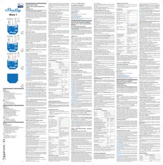
  • 1. EN USER AND SAFETY GUIDE Z-Wave™ smart switch with potential-free contacts READ BEFORE USE This document contains important technical and safety informa- tion about the Device, its safe use and installation. ⚠CAUTION! Before beginning the installation, please read carefully and entirely this guide and any other documents accompanying the device. Failure to follow the installation procedures could lead to malfunction, danger to your health and life, violation of law or refusal of legal and/or commercial guarantee (if any). Shelly Europe Ltd. is not responsible for any loss or damage in case of incorrect installa- tion or improper operation of this Device due to failure of following the user and safety instructions in this guide. TERMINOLOGY Gateway – A Z-Wave™ gateway, also referred to as a Z-Wave™ controller, Z-Wave™ main controller, Z-Wave™ primary controller, or Z-Wave™ hub, etc., is a device that serves as a central hub for a Z-Wave™ smart home network. The term “gateway” is used in this document. S button - The Z-Wave™ Service button, which is located on Z-Wave™ devices and is used for various functions such as adding (inclusion), removing (exclusion), and resetting the device to its fac- tory default settings. The term "S button" is used in this document. Device – In this document, the term “Device” is used to refer to the Wave 1 device. ABOUT SHELLY QUBINO Shelly Qubino is a line of innovative microprocessor-managed devices, which allow remote control of electric circuits with a smartphone, tablet, PC, or home automation system. They work on Z-Wave™ wireless communication protocol, using a gateway. When the gateway is connected to the internet, you can control Shelly Qubino devices remotely from anywhere. Shelly Qubino devices can be operated in any Z-Wave™ network with other Z-Wave™ certified devices from other manufacturers. All mains operated nodes within the network will act as repeaters regardless of vendor to increase reliability of the network. Devices are designed to work with older generations of Z-Wave™ devices and gateways. ABOUT THE WAVE 1 The Wave 1 (Device) controls on/off function for one electrical device, e.g., bulb, ceiling fan, IR heater, electrical locks, garage doors, irrigation system, etc. The output contact is potential-free (dry contact), so different power supply loads (up to 16 A) can be connected to the Device. It is compatible with push-buttons and switches (default). ELECTRICAL DIAGRAM (110-240 V AC / 24-48 V DC / 12 V DC) Refer to the schematics (Fig. 1-3) in this user guide. INSTALLATION INSTRUCTIONS The Device can control a various type of loads (e.g., bulbs) in one electrical circuit up to 3.5 kW / 240 V AC. It can be retrofitted into standard electrical wall boxes, behind power sockets and light switches or other places with limited space. ⚠CAUTION! Danger of electrocution. Mounting/installation of the Device to the power grid has to be performed with caution, by a qualified electrician. ⚠WARNING! Danger of electrocution. Every change in the connec- tions has to be done after ensuring there is no voltage present at the Device terminals. ⚠CAUTION! Use the Device only with a power grid and applianc- es that comply with all applicable regulations. A short circuit in the power grid or any appliance connected to the Device may damage it. ⚠CAUTION! Do not connect the Device to appliances exceeding the given max. load! ⚠CAUTION! Do not shorten the antenna. ⚠RECOMMENDATION: Place the antenna as far away as possible from metal elements as they can cause signal interference. ⚠CAUTION! Connect the Device only in the way shown in these instructions. Any other method could cause damage and/or injury. ⚠CAUTION! Do not install the Device where it can get wet. ⚠CAUTION! Do not use the Device if it has been damaged! ⚠CAUTION! Do not attempt to service or repair the Device yourself! ⚠RECOMMENDATION: Connect the Device using solid single-core wires with increased insulation heat resistance not less than PVC T105°C (221°F). ⚠CAUTION! Before starting the mounting/installation of the De- vice, check that the breakers are turned off and there is no voltage on their terminals. This can be done with a phase tester or multime- ter. When you are sure that there is no voltage, you can proceed to connecting the wires. Connect the load circuit to the Device I and O terminals. If you are using AC power supply for the Device, connect the Live wire to the Device L terminal, and the Neutral wire to the N terminal as shown on Fig. 1. Connect a switch or a push-button to the Device SW terminal and the Live wire. If you are using 24-48 V DC power supply (Fig. 2), connect the + wire to the + and the GND wire to the terminal of the Device. If you are using stabilized 12 V DC power supply (Fig. 3), connect the + wire to the 12V+ terminal, instead to the + terminal. Connect the switch/push-button to the “SW” terminal and the GND wire. ⚠RECOMMENDATION: For inductive appliances that cause volt- age spikes during switching on/off, such as electrical motors, fans, vacuum cleaners and similar ones, RC snubber (0.1 µF / 100 Ω / 1/2 W / 600 VAC) should be connected parallel to the appliance. ⚠CAUTION! Do not allow children to play with the push-buttons/ switches connected to the Device. Keep the devices for remote control of Shelly Qubino (mobile phones, tablets, PCs) away from children. Z-WAVE™ ADDING/REMOVING (INCLUSION/EXCLUSION) SmartStart adding (inclusion): SmartStart enabled products can be added into a Z-Wave™ network by scanning the Z-Wave™ QR Code present on the Device with a gateway providing SmartStart inclusion. No further action is re- quired, and the SmartStart device will be added automatically with- in 10 minutes of being switched on in the network vicinity. 1. With the gateway application scan the QR code on the Device label and add the Security 2 (S2) Device Specific Key (DSK) to the Provisioning List in the gateway. 2. Connect the Device to a power supply. 3. Check if the blue LED is blinking in Mode 1. If so, the Device is not added to a Z-Wave™ network. 4. Adding will be initiated automatically within a few seconds after connecting the Device to a power supply, and the Device will be added to a Z-Wave™ network automatically. 5. The blue LED will be blinking in Mode 2 during the adding pro- cess. 6. The load connected to O will be blinking 1s on/1s off/1s on/1s off if the Device is successfully added to a Z-Wave™ network. 7. The green LED will be blinking in Mode 1 if the Device is success- fully added to a Z-Wave™ network. Adding (inclusion) with a switch/push-button: 1. Connect the Device to a power supply. 2. Check if the blue LED is blinking in Mode 1. If so, the Device is not added to a Z-Wave™ network. 3. Enable add/remove mode on the gateway. 4. Toggle the switch/push-button connected to the SW terminal 3 times within 3 seconds (this procedure puts the Device in LEARN MODE*). The Device must receive on/off signal 3 times, which means pressing the push-button 3 times, or toggling the switch on and off 3 times. 5. The blue LED will be blinking in Mode 2 during the adding pro- cess. 6. The load connected to O will be blinking 1s on/1s off/1s on/1s off if the Device is successfully added to a Z-Wave™ network. 7. The green LED will be blinking in Mode 1 if the Device is success- fully added to a Z-Wave™ network. *LEARN MODE state allows the Device to receive network informa- tion from the gateway. Adding (inclusion) with the S button: 1. Connect the Device to a power supply. 2. Check if the blue LED is blinking in Mode 1. If so, the Device is not added to a Z-Wave™ network. 3. Enable add/remove mode on the gateway. 4. To enter the Setting mode, quickly press and hold the S button on the Device until the LED turns Solid blue. 5. Quickly release and then press and hold (> 2 s) the S button on the Device until the blue LED starts blinking in Mode 3. Releasing the S button will start the LEARN MODE. 6. The blue LED will be blinking in Mode 2 during the adding pro- cess. 7. The load connected to O will be blinking 1s on/1s off/1s on/1s off if the Device is successfully added to a Z-Wave™ network. 8. The green LED will be blinking in Mode 1 if the Device is success- fully added to a Z-Wave™ network. Note! In Setting mode, the Device has a timeout of 10s before enter- ing again into Normal mode. Note! In case of Security 2 (S2) adding (inclusion), a dialog will ap- pear asking you to enter the corresponding PIN code (5 underlined digits) that are written on the DSK label on the side of the Device and on the DSK label inserted in the packaging. IMPORTANT: The PIN code must not be lost. Removing (exclusion) with a switch/push-button: 1. Connect the Device to a power supply. 2. Check if the green LED is blinking in Mode 1. If so, the Device is added to a Z-Wave™ network. 3. Enable add/remove mode on the gateway. ORDERING CODE: QNSW-001X16XX XX – Values define product version per region. DECLARATION OF CONFORMITY Hereby, Shelly Europe Ltd. (former Allterco Robotics EOOD) de- clares that the radio equipment type Wave 1 is in compliance with Directive 2014/53/EU, 2014/35/EU, 2014/30/EU, 2011/65/EU. The full text of the EU declaration of conformity is available at the fol- lowing internet address: https://shelly.link/Wave1-DoC MANUFACTURER: Shelly Europe Ltd. Address: 103 Cherni vrah Blvd., 1407 Sofia, Bulgaria Tel.: +359 2 988 7435 E-mail: zwave-shelly@shelly.cloud Support: https://support.shelly.cloud/ Web: https://www.shelly.com Changes in the contact data are published by the Manufacturer at the official website: https://www.shelly.com DE BENUTZER- UND SICHERHEITSHANDBUCH Smarter Z-Wave™-Switch mit potenzialfreien Kontakten BITTE VOR GEBRAUCH DURCHLESEN Dieses Dokument enthält wichtige technische und sicherheits- technische Informationen über das Gerät und seine sichere Ver- wendung und Installation. ⚠ACHTUNG! Bevor Sie mit der Installation beginnen, lesen Sie bit- te die Begleitdokumentation sorgfältig und vollständig durch. Die Nichtbeachtung der empfohlenen Verfahren kann zu Fehlfunktio- nen, Lebensgefahr oder Gesetzesverstößen führen. Shelly Europe Ltd. haftet nicht für Verluste oder Schäden im Falle einer falschen Installation oder Bedienung dieses Geräts. TERMINOLOGIE Gateway - Ein Z-Wave™-Gateway, auch als Z-Wave™-Controller, Z-Wave™-Hauptcontroller, Z-Wave™-Primärcontroller oder Z-Wave™- Hub usw. bezeichnet, ist ein Gerät, das als zentraler Hub für ein Z-Wave™-Smart-Home-Netzwerk dient. In diesem Dokument wird der Begriff "Gateway" verwendet. S-Taste - Die Z-Wave™ Service-Taste, die sich auf Z-Wave™-Geräten befindet und für verschiedene Funktionen wie die Aufnahme (Hinzufügen), der Ausschluss (Entfernen) und das Zurücksetzen des Geräts auf die Werkseinstellungen verwendet wird. In diesem Dokument wird der Begriff "S-Taste" verwendet. Gerät - In diesem Dokument wird der Begriff "Gerät" für das Wave 1 Gerät verwendet. ÜBER SHELLY QUBINO Shelly Qubino ist eine Reihe innovativer, mikroprozessorgesteuert- er Geräte, die die Fernsteuerung von Stromkreisen mit einem Smartphone, Tablet, PC oder einem Hausautomatisierungssystem ermöglichen. Sie arbeiten mit dem drahtlosen Z-Wave™-Kommu- nikationsprotokoll unter Verwendung eines Gateways. Wenn das Gateway mit dem Internet verbunden ist, können Sie die Shelly Qubino Geräte von überall aus fernsteuern. Shelly Qubino Geräte können in jedem Z-Wave™ Netzwerk mit anderen Z-Wave™ zertifi- zierten Geräten anderer Hersteller betrieben werden. Alle netzbe- triebenen Knotenpunkte innerhalb des Netzwerks werden unabhän- gig vom Hersteller als Repeater fungieren, um die Zuverlässigkeit des Netzwerks zu erhöhen. Die Geräte sind so konzipiert, dass sie mit älteren Generationen von Z-Wave™-Geräten und Gateways funktionieren. ÜBER DAS WAVE 1 Das Wave 1 (Gerät) steuert die Ein- und Ausschaltfunktion für ein elektrisches Gerät, z. B. Glühbirne, Deckenventilator, IR-Heizung, elektrische Schlösser, Garagentore, Bewässerungsanlage, etc. Der Ausgangskontakt ist potentialfrei (Trockenkontakt), so dass verschiedene Stromversorgungslasten (bis zu 16 A) an das Gerät angeschlossen werden können. Es ist kompatibel mit Drucktasten und Schaltern (Standard). ELEKTRISCHER SCHALTPLAN (110–240 V AC / 24–48 V DC / 12 V DC) SehenSiesichdieSchaltpläne(Abb.1–3)indiesemBenutzerhandbuchan. INSTALLATIONSANLEITUNG Das Gerät kann verschiedene Arten von Lasten (z. B. Glühbirnen) in einem Stromkreis bis zu 3,5 kW / 240 V AC steuern. Es kann in eine Standard-Unterputzkonsole nachgerüstet werden, hinter Steckdosen und Lichtschaltern oder an anderen Orten mit begrenz- tem Platz vorgesehen. ⚠VORSICHT! Gefahr eines Stromschlages. Die Montage/Installa- tion des Geräts an das Stromnetz muss von einem qualifizierten Elektriker mit Vorsicht durchgeführt werden! ⚠VORSICHT! Es besteht Stromschlaggefahr. Bei jeder Änderung der Anschlüsse muss sichergestellt werden, dass an den Klemmen des Geräts keine Spannung anliegt! ⚠VORSICHT! Verwenden Sie das Gerät nur mit einem Stromnetz und Geräten, die allen geltenden Vorschriften entsprechen. Ein Kurzschluss im Stromnetz oder in einem an das Gerät angeschlos- senen Gerätes kann dieses beschädigen! ⚠VORSICHT! Schließen Sie das Gerät nicht an Geräte an, die die angegebene Höchstlast überschreiten! ⚠VORSICHT! Kürzen Sie die Antenne nicht! ⚠EMPFEHLUNG: Stellen Sie die Antenne möglichst weit von metallischen Gegenständen auf, da diese Signalstörungen verur- sachen können. ⚠VORSICHT! Schließen Sie das Gerät nur auf die in dieser Anlei- tung beschriebene Weise an. Jede andere Methode kann zu Schä- den und/oder Verletzungen führen! ⚠VORSICHT! Installieren Sie das Gerät nicht an einem Ort, an dem es nass werden kann! ⚠VORSICHT! Verwenden Sie das Gerät nicht, wenn es beschädigt ist! ⚠VORSICHT! Versuchen Sie nicht, das Gerät selbst zu warten oder zu reparieren! ⚠EMPFEHLUNG: Schließen Sie das Gerät mit massiven einadri- gen Kabeln mit erhöhter Isolationswärmebeständigkeit von min- destens PVC T105°C (221°F) an! ⚠VORSICHT! Bevor Sie mit der Installation/Montage des Geräts beginnen, prüfen Sie, ob die Leitungsschutzschalter (Sicherungen) ausgeschaltet sind und keine Spannung an den Klemmen anliegt. Dies kann mit einem Phasenprüfer oder Multimeter erfolgen. Wenn Sie sicher sind, dass keine Spannung anliegt, können Sie mit dem Anschluss der Kabel fortfahren! Verbinden Sie den Lastkreis mit den Klemmen I und O. Wenn Sie das Gerät mit Wechselstrom versorgen, verbinden Sie die Phase mit der L-Klemme des Geräts und den Neutralleiter mit der N-Klemme, wie in Abb. 1 dargestellt. Verbinden Sie einen Schal- ter/Druckknopf mit der Klemme SW und der Phase. Wenn Sie eine 24-48 V Gleichstromversorgung verwenden (Abb. 2), verbinden Sie +-Kabel mit der +-Klemme und GND mit der -Klemme des Geräts. Wenn Sie eine konstante 12 V Gleichstromversorgung verwenden (Abb. 3), verbinden Sie das +-Kabel mit der 12V+-Klemme und GND mit der -Klemme des Geräts. Verbinden Sie den Schalter/Druck- knopf mit der SW-Klemme und dem GND-Kabel. ⚠EMPFEHLUNG: Bei induktiven Geräten, die beim Ein- und Aus- schalten Spannungsspitzen verursachen, wie z. B. Elektromotoren, Ventilatoren, Staubsauger und ähnliche, sollte ein RC-Snubber (0,1 µF / 100 Ω / 1/2 W / 600 VAC) parallel zum Gerät angeschlossen werden. ⚠VORSICHT! Erlauben Sie Kindern nicht, mit den an das Gerät angeschlossenen Druckknopf /Schaltern zu spielen. Halten Sie die Geräte zur Fernsteuerung des Shelly Qubino (z.B.: Mobiltelefone, Tablets, PCs) von Kindern fern. Z-WAVE™ HINZUFÜGEN/ENTFERNEN (AUFNAHME/ AUSSCHLUSS) Hinzufügen (Aufnahme) von SmartStart: SmartStart-fähige Produkte können in ein Z-Wave™-Netzwerk aufgenommen werden, indem der Z-Wave™ QR-Code auf dem Gerät mit einem Gateway gescannt wird, das die SmartStart-Ein- bindung ermöglicht. Es sind keine weiteren Schritte erforderlich, und das SmartStart-Gerät wird innerhalb von 10 Minuten nach dem Einschalten automatisch in der Nähe des Netzwerks hinzugefügt. 1. Scannen Sie mit der Gateway-Anwendung den QR-Code auf dem Geräteetikett und fügen Sie den Security 2 (S2) Device Specific Key (DSK) zur Provisioning List im Gateway hinzu. 2. Schließen Sie das Gerät an eine Stromversorgung an. 3. Prüfen Sie, ob die blaue LED in Modus 1 blinkt. Ist dies der Fall, wird das Gerät nicht in ein Z-Wave™-Netzwerk hinzugefügt. 4. Die Aufnahme (Hinzufügen) wird automatisch innerhalb weniger Sekunden nach dem Anschluss des Geräts an die Stromversorgung eingeleitet und das Gerät wird automatisch in das Z-Wave™-Netzw- erk aufgenommen. 5. Die blaue LED blinkt im Modus 2 während des Aufnahmevor- gangs (Hinzufügen). 6. Die an O angeschlossene Last blinkt 1 s Ein/1 s Aus/1 s Ein/1 s Aus, wenn das Gerät erfolgreich in ein Z-Wave™-Netzwerk hinzuge- fügt wurde. 7. Die grüne LED blinkt im Modus 1, wenn das Gerät erfolgreich zu einem Z-Wave™-Netzwerk hinzugefügt wurde. Hinzufügen (Aufnahme) mit einem Schalter/Druckknopf: 1. Schließen Sie das Gerät an eine Stromversorgung an. 2. Prüfen Sie, ob die blaue LED in Modus 1 blinkt. Ist dies der Fall, wird das Gerät nicht in ein Z-Wave™-Netzwerk hinzugefügt. 3. Aktivieren Sie den Hinzufügen/Entfernen-Modus auf dem Gateway. 4. Schalten Sie den Schalter/Druckknopf, der mit der SW-Klemme verbunden ist, 3 Mal innerhalb von 3 Sekunden um (dieser Vorgang versetzt das Gerät in den LEARN MODE*). Das Gerät muss 3 Mal ein Ein/Aus-Signal empfangen, d. h. 3 Mal den Druckknopf drücken oder den Schalter 3 Mal ein- und ausschalten. 5. Die blaue LED blinkt im Modus 2 während des Aufnahmevor- UNTERSTÜTZTE LASTTYPEN • Kapazitiv (Kondensatorbatterien, elektronische Geräte, Motor- startkondensatoren) • Induktiv mit RC Snubber (LED-Lichttreiber, Transformatoren, Ven- tilatoren, Kühlschränke, Klimageräte) SPEZIFIKATION Energieversorgung 110-240 V AC / 24-48 V DC / 12 V DC ± 10% Stromverbrauch < 0.3 W Max. Schaltspannung Wechsel- strom AC 240 V Max. Schaltstrom Wechsel- strom AC 16 A Max. Schaltspannung Gleich- strom DC 30 V Max. Schaltstrom Gleichstrom DC 10 A Überhitzungsschutz Ja Entfernung Bis zu 40 m in Innenräumen (131 ft.) (abhängig von den örtlichen Gegebenheiten) Z-Wave™ Repeater Ja CPU Z-Wave™ S800 Z-Wave™ Frequenzbänder 868,4 MHz; 865,2 MHz; 869,0 MHz; 921,4 MHz; 908,4 MHz; 916 MHz; 919,8 MHz; 922,5 MHz; 919,7-921,7-923,7 MHz; 868,1 MHz; 920,9 MHz Maximale übertragene Funkfrequenzleistung in Frequenzband(en) < 25 mW Größe (H × B × T) 37x42x16 ±0.5 mm / 1.46x1.65x0.63 ±0.02 in Gewicht 26 g / 0.92 oz. Montage Wandkonsole Schraubklemmen max. Drehmoment 0.4 Nm / 3.5 lbin Querschnitt des Leiters 0.5 bis 1.5 mm² / 20 bis 16 AWG Länge des abisolierten Leiters 5 bis 6 mm / 0.20 bis 0.24 in Gehäusematerial Kunststoff Farbe Blau Umgebungstemperatur -20°C bis 40°C / -5°F bis 105°F Luftfeuchtigkeit 30% bis 70% RH Max. Höhe 2000 m / 6562 ft. WICHTIG Die Z-Wave™ drahtlose Kommunikation ist nicht immer 100 % ver- lässlich. Dieses Modul soll nicht in Situationen verwendet werden, in denen menschliches Leben oder Wertgegenstände allein von der Funktion des Moduls abhängen. Falls das Modul von Ihrem Controller nicht erkannt oder falsch angezeigt wird, müssen Sie eventuell den Gerätetyp manuell eingeben und sicherstellen, dass ihr Gateway- Con- troller Z-Wave Plus™ Helligkeitsregler unterstützt. BESTELLCODES : QNSW-001X16XX XX - Werte geben die Produktversion bezogen auf die Region an. KONFORMITÄTSERKLÄRUNG Hiermit erklärt Shelly Europe Ltd. (ehemals Allterco Robotics EOOD), dass der Funkanlagentyp Wave 1 der Richtlinie 2014/53/EU, 2014/35/EU, 2014/30/EU, 2011/65/EU entspricht. Den vollständigen Text der EU-Konformitätserklärung finden Sie unter folgender Inter- netadresse: https://shelly.link/Wave1-DoC HERSTELLER: Shelly Europe Ltd. Adresse: 103 Cherni vrah Blvd., 1407 Sofia, Bulgarien Tel.: +359 2 988 7435 E-mail: zwave-shelly@shelly.cloud Kundensupport: https://support.shelly.cloud/ Offizielle Website: https://www.shelly.com Änderungen der Kontaktdaten werden vom Hersteller auf dessen offi- ziellen Website veröffentlicht: https://www.shelly.com IT GUIDA ALL'USO E ALLA SICUREZZA Interruttore intelligente Z-Wave™ con contatti a potenziale zero LEGGERE PRIMA DELL'USO Questo documento contiene importanti informazioni tecniche e di sicurezza sul Dispositivo e sul suo uso e installazione in sicurezza. ⚠ATTENZIONE! Prima di iniziare l’installazione leggere attenta- mente e completamente la documentazione allegata. La mancata osservanza delle procedure consigliate potrebbe portare a malfun- zionamenti, pericolo per la vita o violazione della legge. Shelly Eu- rope Ltd. non è responsabile per eventuali perdite o danni in caso di installazione o funzionamento errati di questo Dispositivo. TERMINOLOGIA Gateway – Un gateway Z-Wave™, anche chiamato controller Z-Wave™, controller principale Z-Wave™, hub Z-Wave™, ecc., è un dispositivo che funge da hub centrale per una rete domestica in- telligente in tecnologia Z-Wave™. In questo documento si utilizzerà semplicemente il termine "gateway". Pulsante S – E’ il pulsante di Servizio Z-Wave™, che si trova sui dispositivi Z-Wave™ e viene utilizzato per varie funzioni come per l'inclusione (aggiunta), l'esclusione (rimozione) e il ripristino delle impostazioni predefinite di fabbrica del dispositivo. In questo docu- mento si utilizzerà semplicemente il termine "pulsante S". Dispositivo - In questo documento, il termine "Dispositivo" viene utilizzato per fare riferimento al dispositivo Wave 1. A PROPOSITO DI SHELLY QUBINO Shelly Qubino è una linea di dispositivi innovativi gestiti da micro- processore, che consentono il controllo remoto dei circuiti elettrici con smartphone, tablet, PC o sistema domotico. Funzionano su protocollo di comunicazione wireless Z-Wave™, utilizzando un gateway. Quando il gateway è connesso a Internet, puoi controllare i dispositivi Shelly Qubino in remoto da qualsiasi luogo. I dispositivi Shelly Qubino possono essere utilizzati in qualsiasi rete Z-Wave™ con altri dispositivi certificati Z-Wave™ di altri produttori. Tutti i nodi gestiti dalla rete all'interno della rete fungeranno da ripetitori indip- endentemente dal fornitore per aumentare l'affidabilità della rete. I dispositivi sono progettati per funzionare con le generazioni prec- edenti di dispositivi e gateway Z-Wave™. A PROPOSITO DI WAVE 1 Il Wave 1 (Dispositivo) controlla la funzione on/off per un disposi- tivo elettrico, ad es. lampadina, ventilatore da soffitto, riscaldatore IR, serrature elettriche, porte del garage, sistema di irrigazione, ecc. Il contatto di uscita è a potenziale zero (contatto pulito), quindi al Dispositivo possono essere collegati diversi carichi di alimentazi- one (fino a 16 A). È compatibile con pulsanti e interruttori (default). SCHEMA ELETTRICO (110-240 V CA / 24-48 V CC / 12 V CC) Fare riferimento agli schemi (Fig. 1-3) in questa guida per l'utente. ISTRUZIONI PER L'INSTALLAZIONE Il Dispositivo può controllare vari tipi di carichi (ad es. lampadine) in un circuito elettrico fino a 3,5 kW / 240 V CA. Può essere adattato a una console da incasso standard, dietro prese di corrente e inter- ruttori della luce o in altri luoghi con spazio limitato. ⚠ATTENZIONE! Pericolo di folgorazione. Il montaggio/installa- zione del Dispositivo alla rete elettrica deve essere eseguito con cautela da un elettricista qualificato. ⚠ATTENZIONE! Pericolo di folgorazione. Ogni modifica dei colle- gamenti deve essere effettuata dopo essersi assicurati che non ci sia tensione sui terminali del Dispositivo. ⚠ATTENZIONE! Utilizzare il Dispositivo solo con una rete elettrica e con apparecchi conformi a tutte le norme vigenti. Un cortocircuito nella rete elettrica o in qualsiasi apparecchio collegato al Disposi- tivo può danneggiarlo. ⚠ATTENZIONE! Non collegare il Dispositivo ad apparecchi che superano il carico massimo indicato! ⚠ATTENZIONE! Non accorciare l'antenna. ⚠RACCOMANDAZIONE: Posizionare l'antenna il più lontano possibile da elementi metallici in quanto essi potrebbero causare interferenze di segnale. ⚠ATTENZIONE! Collegare il Dispositivo solo nel modo indicato in queste istruzioni. Qualsiasi altro metodo potrebbe causare danni e/o lesioni. ⚠ATTENZIONE! Non installare il Dispositivo in un luogo che possa bagnarsi. ⚠ATTENZIONE! Non utilizzare il Dispositivo se è stato danneggiato! ⚠ATTENZIONE! Non tentare di riparare o riparare il Dispositivo da soli! ⚠RACCOMANDAZIONE: Collegare il Dispositivo utilizzando cavi unipolari solidi con una maggiore resistenza termica dell'isolamen- to non inferiore a PVC T105°C (221°F). ⚠ATTENZIONE! Prima di iniziare l'installazione/montaggio del Dispositivo, controllare che gli interruttori siano spenti e che non ci sia tensione sui loro terminali. Questo può essere fatto con un misuratore di fase o un multimetro. Quando siete sicuri che non c'è tensione, potete procedere al collegamento dei cavi. 4. Toggle the switch/push-button connected to the SW terminal 3 times within 3 seconds (this procedure puts the Device in LEARN MODE*). The Device must receive on/off signal 3 times, which means pressing the push-button 3 times, or toggling the switch on and off 3 times. 5. The blue LED will be blinking in Mode 2 during the removing process. 6. The load connected to O will be blinking 1s on/1s off/1s on/1s off if the Device is successfully removed from a Z-Wave™ network. 7. The blue LED will be blinking in Mode 1 if the Device is success- fully removed from a Z-Wave™ network. Removing (exclusion) with the S button: 1. Connect the Device to a power supply. 2. Check if the green LED is blinking in Mode 1. If so, the Device is added to a Z-Wave™ network. 3. Enable add/remove mode on the gateway. 4. To enter the Setting mode, quickly press and hold the S button on the Device until the LED turns Solid blue. 5. Quickly release and then press and hold (> 2s) the S button on the Device until the blue LED starts blinking in Mode 3. Releasing the S button will start the LEARN MODE. 6. The blue LED will be blinking in Mode 2 during the removing process. 7. The load connected to O will be blinking 1s on/1s off/1s on/1s off if the Device is successfully removed from a Z-Wave™ network. 8. The blue LED will be blinking in Mode 1 if the Device is success- fully removed from a Z-Wave™ network. Note! In Setting mode, the Device has a timeout of 10s before enter- ing again into Normal mode. FACTORY RESET After Factory reset, all custom parameters and stored values (as- sociations, routings, etc.) will return to their default state. HOME ID and NODE ID assigned to the Device will be deleted. Use this reset procedure only when the gateway is missing or otherwise inoperable. Factory reset with a switch/push-button: Note! Factory reset with the switch/push-button is only possible with- in the first minute after the Device is connected to a power supply. 1. Connect the Device to a power supply. 2. Toggle the switch/push-button connected to the SW terminal 5 times within 3 seconds. The Device must receive on/off signal 5 times, which means pressing the push-button 5 times, or toggling the switch on and off 5 times. 3. During factory reset, the LED will turn solid green for about 1s, then the blue and red LED will start blinking in Mode 3 for approx. 2s. 4. The blue LED will be blinking in Mode 1 if the Factory reset is successful. Factory reset with the S button: Note! Factory reset with the S button is possible anytime. 1. To enter the Setting mode, quickly press and hold the S button on the Device until the LED turns Solid blue. 2. Press the S button multiple times until the LED turns Solid red. 3. Press and hold (> 2s) S button on the Device until the red LED starts blinking in Mode 3. Releasing the S button will start the fac- tory reset. 4. During factory reset, the LED will turn solid green for about 1s, then the blue and red LED will start blinking in Mode 3 for approx. 2s. 5. The blue LED will be blinking in Mode 1 if the Factory reset is successful. NOTE: For more information about this Device refer to the Extended User Guide available at: https://kb.shelly.cloud/ LED SIGNALIZATION LED blinking modes Mode 1 0,5s On/2s Off Mode 2 0,5s On/0,5s Off Mode 3 0,1s On/0,1s Off Mode 4 (1x to 6x - 0,2s On/0,2s Off) + 2s Off Normal mode Colour LED mode Removed/Excluded Blue Mode 1 Added/Included Green Mode 1 Setting mode (with S button) Adding/Removing (Inclusion/Exclusion) menu selected Blue Solid Adding/Removing (Inclusion/Exclusion) menu - while pressing S button - Adding/Removing (Inclusion/Exclusion) process selected Blue Mode 3 Factory reset menu selected Red Solid Factory reset - while pressing S button - Factory reset process selected Red Mode 3 “Setting in progress” mode Factory reset and reboot B l u e / R e d / Green ** Adding/Removing (Inclusion/Exclusion) Blue Mode 2 OTA firmware updating B l u e / Red Mode 2 Alarm mode Overheat detected Red Mode4(2x) ** The LED will turn solid green for about 1s, then the blue and red LED will start blinking in Mode 3 for approx. 2s. LED will turn off 30 minutes after the power cycle. Every time you press on the S button, the LED will turn on for 30 minutes. If alarm is active, LED will not turn off. OPERATIONAL INSTRUCTIONS If the SW is configured as a switch (default), each toggle of the switch will change the output O state to the opposite state - on, off, on, etc. If the SW is configured as a push-button in the Device settings, each press of the push-button will change the output O state to the opposite state - on, off, on, etc. SUPPORTED LOAD TYPES • Resistive (incandescent bulbs, heating devices) • Capacitive (capacitor banks, electronic equipment, motor start capacitors) • Inductive with RC Snubber (LED light drivers, transformers, fans, refrigerators, air-conditioners) SPECIFICATIONS Power supply 110-240 V AC / 24-48 V DC / 12 V DC ± 10% Power consumption < 0.3 W Max. switching voltage AC 240 V Max. switching current AC 16 A Max. switching voltage DC 30 V Max. switching current DC 10 A Overheating protection Yes Distance Up to 40 m indoors (131 ft.) (depends on local condition) Z-Wave™ repeater Yes CPU Z-Wave™ S800 Z-Wave™ frequency bands 868,4 MHz; 865,2 MHz; 869,0 MHz; 921,4 MHz; 908,4 MHz; 916 MHz; 919,8 MHz; 922,5 MHz; 919,7-921,7-923,7 MHz; 868,1 MHz; 920,9 MHz Maximum radio frequency power transmitted in frequency band(s) < 25 mW Size (H x W x D) 37x42x16 ±0.5 mm / 1.46x1.65x0.63 ±0.02 in Weight 26 g / 0.92 oz. Mounting Wall console Screw terminals max. torque 0.4 Nm / 3.5 lbin Conductor cross section 0.5 to 1.5 mm² / 20 to 16 AWG Conductor stripped length 5 to 6 mm / 0.20 to 0.24 in Shell material Plastic Color Blue Ambient temperature -20°C to 40°C / -5°F to 105°F Humidity 30% to 70% RH Max. altitude 2000 m / 6562 ft. IMPORTANT DISCLAIMER Z-Wave™ wireless communication may not always be 100% reliable. This Device should not be used in situations in which life and/or va- luables are solely dependent on its functioning. If the Device is not recognized by your gateway or appears incorrectly, you may need to change the Device type manually and ensure that your gateway sup- ports Z-Wave Plus™ multi-level devices. gangs (Hinzufügen). 6. Die an O angeschlossene Last blinkt 1 s Ein/1 s Aus/1 s Ein/1 s Aus, wenn das Gerät erfolgreich in ein Z-Wave™-Netzwerk hinzuge- fügt wurde. 7. Die grüne LED blinkt im Modus 1, wenn das Gerät erfolgreich zu einem Z-Wave™-Netzwerk hinzugefügt wurde. *Der Status LEARN MODE ermöglicht es dem Gerät, Netzwerkinfor- mationen vom Gateway zu empfangen. Hinzufügen (Aufnahme) mit der S-Taste: 1. Schließen Sie das Gerät an eine Stromversorgung an. 2. Prüfen Sie, ob die blaue LED in Modus 1 blinkt. Ist dies der Fall, wird das Gerät nicht in ein Z-Wave™-Netzwerk hinzugefügt. 3. Aktivieren Sie den Hinzufügen/Entfernen-Modus auf dem Gate- way. 4. Um den Einstellungsmodus aufzurufen, halten Sie die S-Taste Sauf dem Gerät kurz gedrückt, bis die LED dauerhaft blau leuchtet. 5. Lassen Sie die S-Taste am Gerät schnell los und halten Sie sie dann gedrückt (> 2 s), bis die blaue LED im Modus 3 zu blinken beginnt. Wenn Sie die S-Taste loslassen, wird der LEARN MODE gestartet. 6. Die blaue LED blinkt im Modus 2 während des Aufnahmevor- gangs (Hinzufügen). 7. Die an O angeschlossene Last blinkt 1 s Ein/1 s Aus/1 s Ein/1 s Aus, wenn das Gerät erfolgreich in ein Z-Wave™-Netzwerk aufge- nommen wurde. 8. Die grüne LED blinkt im Modus 1, wenn das Gerät erfolgreich zu einem Z-Wave™-Netzwerk hinzugefügt wurde. Achtung! Im Einstellungsmodus hat das Gerät einen Timeout von 10s, bevor es wieder in den Normalmodus wechselt. Achtung! Im Falle der Aufnahme (Hinzufügen) von Security 2 (S2) erscheint ein Dialog, in dem Sie aufgefordert werden, die entsprech- ende PIN-Code (5 unterstrichene Ziffern) einzugeben, die auf dem DSK-Etikett an der Seite des Geräts und auf dem DSK-Etikett in der Verpackung angegeben ist. WICHTIG: Der PIN-Code darf nicht verloren gehen. Entfernen (Ausschluss) mit dem Schalter/Druckknopf: 1. Schließen Sie das Gerät an eine Stromversorgung an. 2. Prüfen Sie, ob die grüne LED in Modus 1 blinkt. Wenn ja, wird das Gerät zu einem Z-Wave™-Netzwerk hinzugefügt. 3. Aktivieren Sie den Hinzufügen/Entfernen-Modus auf dem Gate- way. 4. Schalten Sie den Schalter/Druckknopf, der mit der SW-Klemme verbunden ist, 3 Mal innerhalb von 3 Sekunden um (dieser Vorgang versetzt das Gerät in den LEARN MODE*). Das Gerät muss 3 Mal ein Ein/Aus-Signal empfangen, d. h. 3 Mal den Druckknopf drücken oder den Schalter 3 Mal ein- und ausschalten. 5. Die blaue LED blinkt im Modus 2 während des Ausschlussver- fahrens (Entfernen). 6. Die an O angeschlossene Last O blinkt 1 s Ein/1 s Aus/1 s Ein/1 s Aus, wenn das Gerät erfolgreich aus einem Z-Wave™-Netzwerk en- tfernt wurde. 7. Die blaue LED blinkt im Modus 1, wenn das Gerät erfolgreich aus einem Z-Wave™-Netzwerk entfernt wurde. Entfernen (Ausschluss) mit der S-Taste: 1. Schließen Sie das Gerät an eine Stromversorgung an. 2. Prüfen Sie, ob die grüne LED in Modus 1 blinkt. Wenn ja, wird das Gerät zu einem Z-Wave™-Netzwerk hinzugefügt. 3. Aktivieren Sie den Hinzufügen/Entfernen-Modus auf dem Gate- way. 4. Um den Einstellungsmodus aufzurufen, halten Sie die S-Taste auf dem Gerät kurz gedrückt, bis die LED dauerhaft blau leuchtet. 5. Lassen Sie die S-Taste am Gerät schnell los und halten Sie sie dann gedrückt (> 2 s), bis die blaue LED im Modus 3 zu blinken beginnt. Wenn Sie die S-Taste loslassen, wird der LEARN MODE gestartet. 6. Die blaue LED blinkt im Modus 2 während des Ausschlussver- fahrens (Entfernen). 7. Die an O angeschlossene Last O blinkt 1 s Ein/1 s Aus/1 s Ein/1 s Aus, wenn das Gerät erfolgreich aus einem Z-Wave™-Netzwerk entfernt wurde. 8. Die blaue LED blinkt im Modus 1, wenn das Gerät erfolgreich aus einem Z-Wave™-Netzwerk entfernt wurde. Achtung! Im Einstellungsmodus hat das Gerät einen Timeout von 10s, bevor es wieder in den Normalmodus wechselt. ZURÜCKSETZEN AUF DIE WERKSEINSTELLUNGEN Nach dem Zurücksetzen auf die Werkseinstellungen werden alle benutzerdefinierten Parameter und gespeicherten Werte (Zuord- nungen, Routings usw.) auf den Standardzustand zurückgesetzt. HOME ID und NODE ID, die dem Gerät zugewiesen sind, werden gelöscht. Verwenden Sie dieses Verfahren zum Zurücksetzen nur, wenn das Gateway fehlt oder aus anderen Gründen nicht funktions- fähig ist. Zurücksetzen auf die Werkseinstellungen mit dem Schalter/Druckknopf: Achtung! Das Zurücksetzen auf die Werkseinstellungen mit dem Schalter/Druckknopf ist nur innerhalb der ersten Minute möglich, nachdem das Gerät an eine Stromversorgung angeschlossen wurde. 1. Schließen Sie das Gerät an eine Stromversorgung an. 2. Schalten Sie den Schalter/Druckknopf, der mit dem SW-An- schluss verbunden ist, 5 Mal innerhalb von 3 Sekunden um. Das Gerät muss 5 Mal ein Ein/Aus-Signal empfangen, d. h. 5 Mal den Taster drücken oder 5 Mal den Schalter ein- und ausschalten. 3. Während des Zurücksetzens auf die Werkseinstellungen leuchtet die LED für ca. 1 s durchgehend grün, dann beginnen die blaue und rote LED im Modus 3 für ca. 2 s zu blinken. 4. Die blaue LED blinkt im Modus 1, wenn das Zurücksetzen auf die Werkseinstellungen erfolgreich war. Zurücksetzen auf die Werkseinstellungen mit der S-Taste: Achtung! Das Zurücksetzen auf die Werkseinstellungen mit der S-Taste ist jederzeit möglich. 1. Um den Einstellungsmodus aufzurufen, halten Sie die S-Taste auf dem Gerät kurz gedrückt, bis die LED blau leuchtet. 2. Drücken Sie die S-Taste mehrmals, bis die LED dauerhaft rot leuchtet. 3. Halten Sie (> 2 s) die S-Taste am Gerät gedrückt, bis die rote LED im Modus 3 zu blinken beginnt. Wenn Sie die S-Taste loslassen, wird der Werksreset gestartet. 4. Während des Zurücksetzens auf die Werkseinstellungen leuchtet die LED für ca. 1 s durchgehend grün, dann beginnen die blaue und rote LED im Modus 3 für ca. 2 s zu blinken. 5. Die blaue LED blinkt im Modus 1, wenn das Zurücksetzen auf die Werkseinstellungen erfolgreich war. HINWEIS: Weitere Informationen zu diesem Gerät find- en Sie im Erweiterten Benutzerhandbuch auf der Website: https://kb.shelly.cloud/ LED-SIGNALISIERUNG LED-Blinkmodus Modus 1 0,5 s Ein/2 s Aus Modus 2 0,5 s Ein/0,5 s Aus Modus 3 0,1 s Ein/0,1 s Aus Modus 4 (1x bis 6x - 0,2 s Ein/0,2 s Aus) + 2 s Aus Normalmodus Farbe LED-Modus Entfernt/Ausgeschlossen Blau Modus 1 Hinzugefügt/Aufgenommen Grün Modus 1 Einstellungsmodus (mit der S-Taste) Menü Hinzufügen/Entfernen (Auf- nahme/Ausschluss) ausgewählt Blau Dauerhaft Menü Hinzufügen/Entfernen (Aufnahme/ Ausschluss) - bei gedrückter S-Taste - Prozess Hinzufügen/Entfernen (Aufnahme/ Ausschluss) ausgewählt Blau Modus 3 Menü Zurücksetzen auf die Werksein- stellungen ausgewählt Rot Dauerhaft Zurücksetzen auf die Werkseinstellun- gen - bei gedrückter S-Taste - Zurückset- zen auf die Werkseinstellungen Prozess ausgewählt Rot Modus 3 Modus "Einstellung im Gange" Zurücksetzen auf die Werkseinstellun- gen und Neustart B l a u / R o t / Grün ** Hinzufügen/Entfernen (Aufnahme/ Ausschluss) Blau Modus 2 Firmware-Aktualisierung OTA B l a u / Rot Modus 2 Alarmmodus Überhitzung erkannt Rot Modus4(2x) ** Die LED leuchtet für ca. 1 s durchgehend grün, dann beginnen die blaue und rote LED im Modus 3 für ca. 2 s zu blinken. Die LED schaltet sich 30 Minuten nach dem Stromzyklus aus. Jedes Mal, wenn Sie die S-Taste drücken, leuchtet die LED 30 Minuten lang. Wenn der Alarm aktiv ist, schaltet sich die LED nicht aus. BETRIEBLICHE ANWEISUNGEN Wenn der SW als Schalter konfiguriert ist ("Standard"), ändert sich der Zustand des Ausgangs O bei jeder Schaltung des Schalters in den ent- gegengesetzten Zustand - ein, aus, ein... Wenn der SW in den Geräteeinstellungen als Druckknopf konfiguriert ist, ändert jeder Druck auf den Druckknopf den Zustand des Ausgangs O in den entgegengesetzten Zustand - ein, aus, ein... Collegare il circuito di carico ai terminali I e O del Dispositivo. Se si utilizza l'alimentazione CA per il Dispositivo, collegare il filo Sotto tensione al terminale L del Dispositivo e il filo Neutro al ter- minale N come mostrato in fig. 1. Collegare un interruttore o un pulsante al terminale SW del Dispositivo e al filo Sotto tensione. Se si utilizza un'alimentazione 24-48 V CC (fig. 2), collegare il filo + al + e il filo GND ai terminali del Dispositivo. Se si utilizza un alimentatore stabilizzato a 12V CC (fig. 3), collegare il filo + al terminale 12V+, anziché al morsetto +. Collegare l'interrut- tore/pulsante al terminale SW e al filo GND. ⚠RACCOMANDAZIONE: Per gli apparecchi induttivi che causano picchi di tensione durante l'accensione e lo spegnimento, come motori elettrici, ventilatori, aspirapolvere e simili, è necessario col- legare in parallelo all'apparecchio uno snubber RC (0,1µF / 100 Ω / 1/2 W / 600 VAC). ⚠ATTENZIONE! Non permettere ai bambini di giocare con i pul- santi/interruttori collegati al Dispositivo. Tenere i dispositivi per il controllo remoto di Shelly Qubino (telefoni cellulari, tablet, PC) lontano dai bambini. AGGIUNTA/RIMOZIONE (INCLUSIONE/ESCLUSIONE) Z-WAVE™ Aggiunta (inclusione) SmartStart: Se il tuo gateway fornisce l'inclusione SmartStart, i prodotti abilitati SmartStart possono essere aggiunti a una rete Z-Wave™ scansion- ando il codice QR Z-Wave™ presente sul Dispositivo. Non sono necessarie ulteriori azioni e il dispositivo SmartStart verrà aggiunto automaticamente entro 10 minuti dall'accensione nelle vicinanze della rete. 1. Utilizzando l'applicazione del gateway, scansionare il codice QR sull'etichetta del Dispositivo e aggiungere la Device Specific Key (DSK) Security 2 (S2) all'elenco di provisioning del gateway. 2. Collegare il Dispositivo a un alimentazione. 3. Controllare se il LED blu lampeggia in modalità 1. In tal caso, il Dispositivo non è ancora stato aggiunto a una rete Z-Wave™. 4. L'inclusione (aggiunta) verrà avviata automaticamente entro po- chi secondi dal collegamento del Dispositivo a un alimentazione e il Dispositivo verrà aggiunto automaticamente alla rete Z-Wave™. 5. Il LED blu lampeggerà in modalità 2 durante il processo di inclu- sione (aggiunta). 6. Il carico collegato a O lampeggerà per 1s acceso/1s spento/1s acceso/1s spento quando il Dispositivo risulterà aggiunto corretta- mente a una rete Z-Wave™. 7. Il LED verde lampeggerà in modalità 1 se il Dispositivo viene ag- giunto correttamente a una rete Z-Wave™. Aggiunta (inclusione) con interruttore/pulsante: 1. Collegare il Dispositivo a un alimentazione. 2. Controllare se il LED blu lampeggia in modalità 1. In tal caso, il Dispositivo non è ancora stato aggiunto a una rete Z-Wave™. 3. Abilitare la modalità aggiungi/rimuovi sul gateway. 4. Azionare 3 volte nell'arco di 3 secondi l'interruttore/pulsante collegato al terminale SW (questa procedura pone il Dispositivo in LEARN MODE*). Il Dispositivo deve ricevere il segnale di accensi- one/spegnimento 3 volte, il che significa premere il pulsante per 3 volte o accendere e spegnere l'interruttore per 3 volte. 5. Il LED blu lampeggerà in modalità 2 durante il processo di inclu- sione (aggiunta). 6. Il carico collegato a O lampeggerà per 1s acceso/1s spento/1s acceso/1s spento quando il Dispositivo risulterà aggiunto corretta- mente a una rete Z-Wave™ 7. Il LED verde lampeggerà in modalità 1 se il Dispositivo viene ag- giunto correttamente a una rete Z-Wave™. *Lo stato LEARN MODE consente al Dispositivo di ricevere infor- mazioni di rete dal gateway. Aggiunta (inclusione) con il pulsante S: 1. Collegare il Dispositivo a un alimentazione. 2. Controllare se il LED blu lampeggia in modalità 1. In tal caso, il Dispositivo non è ancora stato aggiunto a una rete Z-Wave™. 3. Abilitare la modalità aggiungi/rimuovi sul gateway. 4. Per accedere alla modalità di impostazione, premere rapida- mente e tenere premuto il pulsante S sul Dispositivo finché il LED non diventa blu fisso. 5. Rilasciare rapidamente e quindi tenere premuto (> 2s) il pulsante S sul Dispositivo fino a quando il LED blu inizia a lampeggiare in modalità 3. Rilasciando il pulsante S si avvia la LEARN MODE. 6. Il LED blu lampeggerà in modalità 2 durante il processo di inclu- sione (aggiunta). 7. Il carico collegato a O lampeggerà per 1s acceso/1s spento/1s acceso/1s spento quando il Dispositivo risulterà aggiunto corretta- mente a una rete Z-Wave™. 8.Il LED verde lampeggerà in modalità 1 se il Dispositivo viene aggi- unto correttamente a una rete Z-Wave™. Nota! In modalità Impostazioni il Dispositivo ha un timeout di 10s prima di entrare nuovamente in modalità Normale. Nota! In caso di aggiunta (inclusione) Security 2 (S2), apparirà una finestra di dialogo che chiede di inserire il codice PIN corrisponden- te (5 cifre sottolineate) che è scritto sull'etichetta DSK apposta sul lato del Dispositivo e sull'etichetta DSK inserita nella confezione.. IMPORTANTE: il codice PIN non deve essere perso. Rimozione (esclusione) con interruttore/pulsante: 1. Collegare il Dispositivo a un alimentazione. 2. Verificare se il LED verde lampeggia in modalità 1. In tal caso, il Dispositivo è aggiunto a una rete Z-Wave™. 3. Abilitare la modalità aggiungi/rimuovi sul gateway. 4. Azionare 3 volte nell'arco di 3 secondi l'interruttore/pulsante collegato al terminale SW (questa procedura pone il Dispositivo in LEARN MODE*). Il Dispositivo deve ricevere il segnale di accensi- one/spegnimento 3 volte, il che significa premere il pulsante per 3 volte o accendere e spegnere l'interruttore per 3 volte. 5. Il LED blu lampeggerà in modalità 2 durante il processo di esclu- sione (rimozione). 6. Il carico collegato a O lampeggerà per 1s acceso/1s spento/1s acceso/1s spento quando il dispositivo risulterà rimosso con suc- cesso da una rete Z-Wave™. 7. Il LED blu lampeggerà in modalità 1 se il Dispositivo viene rimos- so con successo da una rete Z-Wave™. Rimozione (esclusione) con il pulsante S: 1. Collegare il Dispositivo a un alimentazione. 2. Verificare se il LED verde lampeggia in modalità 1. In tal caso, il Dispositivo è aggiunto a una rete Z-Wave™. 3. Abilitare la modalità aggiungi/rimuovi sul gateway. 4. Per accedere alla modalità di impostazione, premere rapida- mente e tenere premuto il pulsante S sul Dispositivo finché il LED non diventa blu fisso. 5. Rilasciare rapidamente e quindi tenere premuto (> 2s) il pulsante S sul Dispositivo fino a quando il LED blu inizia a lampeggiare in modalità 3. Rilasciando il pulsante S si avvia la LEARN MODE. 6. Il LED blu lampeggerà in modalità 2 durante il processo di esclu- sione (rimozione). 7. Il carico collegato a O lampeggerà per 1s acceso/1s spento/1s acceso/1s spento quando il Dispositivo risulterà rimosso con suc- cesso da una rete Z-Wave™. 8. Il LED blu lampeggerà in modalità 1 se il Dispositivo viene rimos- so con successo da una rete Z-Wave™. Nota! In modalità Impostazione il Dispositivo ha un timeout di 10s prima di entrare nuovamente in modalità Normale. RIPRISTINO DI FABBRICA Dopo il ripristino delle impostazioni di fabbrica, tutti i parametri personalizzati e i valori memorizzati (associazioni, instradamenti, ecc.) torneranno allo stato predefinito. HOME ID e NODE ID asseg- nati al Dispositivo verranno eliminati. Utilizzare questa procedura di ripristino solo quando il gateway è mancante o altrimenti non funzionante. Ripristino delle impostazioni di fabbrica con l'interru- ttore/pulsante: Nota! Il ripristino delle impostazioni di fabbrica con l'interruttore/ pulsante è possibile solo entro il primo minuto dopo che il Disposi- tivo è stato collegato all'alimentazione. 1. Collegare il Dispositivo a un alimentazione. 2. Azionare 5 volte l'interruttore/pulsante collegato al terminale SW entro 3 secondi. Il Dispositivo deve ricevere il segnale di accensi- one/spegnimento 5 volte, il che significa premere il pulsante 5 volte o accendere e spegnere l'interruttore 5 volte. 3. Durante il ripristino delle impostazioni di fabbrica, il LED diventerà verde fisso per circa 1 secondo, quindi i LED blu e rosso inizieranno a lampeggiare in modalità 3 per circa 2s. 4. Il LED blu lampeggerà in modalità 1 se il ripristino delle im- postazioni di fabbrica ha esito positivo. Ripristino delle impostazioni di fabbrica con il pulsante S: Nota! Il reset di fabbrica con il pulsante S è possibile in qualsiasi momento. 1. Per accedere alla modalità di impostazione, premere rapida- mente e tenere premuto il pulsante S sul Dispositivo finché il LED non diventa blu fisso. 2. Premere più volte il pulsante S fino a quando il LED diventa rosso fisso. 3. Tenere premuto (> 2s) il pulsante S sul Dispositivo finché il LED rosso non inizia a lampeggiare in modalità 3. Il rilascio del pulsante S avvia il ripristino delle impostazioni di fabbrica. 4. Durante il ripristino delle impostazioni di fabbrica, il LED diventerà verde fisso per circa 1s, quindi i LED blu e rosso inizieran- no a lampeggiare in modalità 3 per circa 2s. 5. Il LED blu lampeggerà in modalità 1 se il ripristino delle im- postazioni di fabbrica ha esito positivo. NOTA: per ulteriori informazioni su questo dispositivo, fare riferimento alla Guida utente estesa disponibile su: https://kb.shelly.cloud/ SEGNALAZIONE LED Modalità di lampeggio del LED Modalità 1 0,5s On/2s Off Modalità 2 0,5s On/0,5s Off Modalità 3 0,1s On/0,1s Off Modalità 4 (1x a 6x - 0,2s On/0,2s Off) + 2s Off SW N O L I AC 110-240V DC 24-48V DC 12V AC 16A/240V DC 10A/30V 12V max. 240 V AC max. 30 V DC 110 - 240 V AC + GND SW N O L I AC 110-240V DC 24-48V DC 12V AC 16A/240V DC 10A/30V 12V 24 - 48 V DC max. 240 V AC max. 30 V DC S SW N O L I AC 110-240V DC 24-48V DC 12V AC 16A/240V DC 10A/30V 12V + 12 V DC GND max. 240 V AC max. 30 V DC Fig.1/ Abb.1/ Imagen 1/ Image 1 B3323 Wave 1 EN LEGEND Device terminals: • N: Neutral terminal • L: Live terminal (110–240 V AC) • SW: Switch/push-button input terminal (controlling O) • I: Load circuit input terminal • O: Load circuit output terminal • 12V+: 12 V DC positive terminal • +: 24 - 48 V DC positive terminal • : 12 / 24 - 48 V DC ground terminal • S: S button (Fig. 4) Wires: • N: Neutral wire • L: Live wire (110-240 V AC) • +: 12 / 24-48 V DC positive wire • GND: 12 / 24-48 V DC ground wire DE LEGENDE Geräteanschlüsse: • N: Klemme für Neutralleiter • L: Klemme für Phase (110-240 V AC) • SW: Klemme für Schalterkeingang (Steuerung O) • I: Eingangsklemme des Lastkreises • O: Ausgangsklemme des Lastkreises • 12V+: 12 V DC Klemme für Pluspol • +: 24 - 48 V DC Klemme für Pluspol • : 12 / 24 - 48 V DC Klemme für Minuspol • S: Die S-Taste (Abb. 4) Kabel: • N: Neutralleiter • L: Phasenleiter (110 - 240 V AC) • +: 12 / 24-48 V DC Pluspolkabel • GND: 12 / 24-48 V DC Massekabel IT LEGENDA Terminali del Dispositivo: • N: Terminale neutro • L: Terminale sotto tensione (110-240 V CA) • SW: Terminale di ingresso interruttore/pulsante (controllo O) • I: Terminale di ingresso del circuito di carico • O: Terminale di uscita del circuito di carico • 12V+: Terminale positivo 12 V CC • +: Terminale positivo 24 - 48 V CC • : Terminale di terra 12 / 24 - 48 V CC • S: Pulsante S (Fig. 4) Fili: • N: Filo neutro • L: Filo sotto tensione (110 - 240 V CA) • +: Filo del positivo 12 / 24-48 V CC • GND: Filo di terra 12 / 24-48 V CC Fig.2/ Abb.2/ Imagen 2/ Image 2 Fig.3/ Abb.3/ Imagen 3/ Image 3 Fig.4/ Abb.4/ Imagen 4/ Image 4 V 0.0.12 1/2
  • 2. Modalità normale Colore ModalitàLED Rimosso/Escluso Blu Modalità 1 Aggiunto/Incluso Verde Modalità 1 Modalità di impostazione (con pulsante S) Menu aggiunta/rimozione (inclusione/ esclusione) selezionato Blu Fisso Menu aggiunta/rimozione (inclusione/ esclusione) - mentre si preme il pulsante S - Processo di aggiunta/rimozione (in- clusione/esclusione) selezionato Blu Modalità 3 Menu di ripristino delle impostazioni di fabbrica selezionato Rosso Fisso Ripristino delle impostazioni di fabbrica - mentre si preme il pulsante S - Proces- so di ripristino delle impostazioni di fab- brica selezionato Rosso Modalità 3 Modalità “Impostazione in corso”. Ripristino delle impostazioni di fabbrica e riavvio B l u / Rosso/ Verde ** Aggiunta/Rimozione(Inclusione/Esclusione) Blu Modalità 2 Aggiornamento Firmware OTA B l u / Rosso Modalità 2 Modalità allarme Surriscaldamento rilevato Rosso Modalità 4 (2x) **Il LED diventerà verde fisso per circa 1s, quindi i LED blu e rosso inizieranno a lampeggiare in modalità 3 per circa 2s. Il LED si spegnerà 30 minuti dopo il ciclo di alimentazione. Ogni volta che si preme il pulsante S, il LED si accenderà per 30 minuti. Se l'allar- me è attivo, il LED non si spegne. ISTRUZIONI OPERATIVE Se il SW è configurato come interruttore (impostazione predefinita), ogni commutazione dell'interruttore cambierà lo stato dell'uscita O nello stato opposto: on, off, on, ecc. Se il SW è configurato come pulsante nelle impostazioni del Dispo- sitivo, ogni pressione del pulsante cambia lo stato dell'uscita O in opposto: on, off, on, ecc. TIPI DI CARICO SUPPORTATI • Carico resistivo (lampadine a incandescenza, dispositivi di ri- scaldamento) • Carico capacitivo (banchi di condensatori, apparecchiature elet- troniche, condensatori di avviamento motore) • Carico induttivo con RC Snubber (driver luci LED, trasformatori, ventole, frigoriferi, condizionatori d'aria) SPECIFICHE Alimentazione elettrica 110-240 V CA / 24-48 V CC / 12 V CC ± 10% Consumo di energia < 0.3 W Massimo. tensione di commutazione CA 240 V Massimo. corrente alternata di commutazione 16 A Massimo. tensione di commutazione CC 30 V Massimo. corrente di commutazione CC 10 A Protezione da surriscaldamento Si Distanza fino a 40 m al chiuso (131 piedi) (dipende dalle condizioni locali) Ripetitore Z-Wave™ Sì Processore Z-Wave™ S800 Bande di frequenza Z-Wave™ 868,4 MHz; 865,2 MHz; 869,0 MHz; 921,4 MHz; 908,4 MHz; 916 MHz; 919,8 MHz; 922,5 MHz; 919,7-921,7-923,7 MHz; 868,1 MHz; 920,9 MHz Potenza massima in radiofre- quenza trasmessa nelle bande di frequenza < 25 mW Dimensioni (A x L x P) 37x42x16 ±0.5 mm / 1.46x1.65x0.63 ±0.02 in Peso 26 g / 0.92 oz. Montaggio Quadro elettrico Morsetti a vite max. coppia 0.4 Nm / 3.5 lbin Sezione del conduttore da0,5a1,5mm²/da20a16AWG Lunghezza spelata del conduttore da5a6mm/da0,20a0,24pollici Materiale guscio Plastica Colore Blu Temperatura ambiente Da -20°C a 40°C / da -5°F a 105°F Umidità Dal 30% al 70% RH Massima altitudine 2000 m / 6562 ft. AVVISO IMPORTANTE La comunicazione wireless Z-Wave™ potrebbe non essere sempre affi- dabile al 100%. Questo Dispositivo non deve essere utilizzato in situa- zioni in cui la vita e/o gli oggetti di valore dipendono esclusivamente dal suo funzionamento. Se il Dispositivo non viene riconosciuto dal gateway o viene visualizzato in modo errato, potrebbe essere neces- sario modificare manualmente il tipo di dispositivo e assicurarsi che il gateway supporti i dispositivi multilivello Z-Wave Plus™. CODICE DI ORDINAZIONE: QNSW-001X16XX XX - I valori definiscono la versione del prodotto per regione. DICHIARAZIONE DI CONFORMITÀ Con la presente, Shelly Europe Ltd. (ex Allterco Robotics EOOD) dichiara che il tipo di apparecchiatura radio Wave 1 è conforme alla Direttiva 2014/53/UE, 2014/35/UE, 2014/30/ UE, 2011/65/UE. Il testo completo della dichiarazione di conformità UE è disponibile al seguente indirizzo internet: https://shelly.link/Wave1-DoC PRODUTTORE: Shelly Europe Ltd. Indirizzo: 103 Cherni vrah Blvd., 1407 Sofia, Bulgarien Tel.: +359 2 988 7435 E-mail: zwave-shelly@shelly.cloud Supporto: https://support.shelly.cloud/ Sito web ufficiale: https://www.shelly.com Le modifiche ai dati di contatto sono pubblicate dal Produttore sul sito Web ufficiale: https://www.shelly.com SP MANUAL DE USO Y SEGURIDAD Interruptor inteligente Z-Wave™ con contactos libres de potencial LEA ANTES DE UTILIZAR Este documento contiene información técnica y de seguridad impor- tante sobre el Dispositivo, su uso y su instalación segura. ⚠¡ATENCIÓN! Antes de utilizar el dispositivo, lea atentamente y por completo esta guía y cualquier otro documento que acompañe al Dispositivo. El incumplimiento de los procedimientos de instala- ción podría provocar un mal funcionamiento, peligro para su salud y su vida, violación de la ley o denegación de la garantía legal y/o comercial (si la hubiera). Shelly Europe Ltd. no se responsabiliza de ninguna pérdida o daño en caso de instalación incorrecta o funcio- namiento inadecuado de este Dispositivo por no haber seguido las instrucciones de uso y seguridad de esta guía. TERMINOLOGIA Gateway – Un gateway Z-Wave™ controlador domotico Z-Wave™ tambien denominado controlador Z-Wave™, controlador principal Z-Wave™ o hub Z-Wave™ etc. es el dispositivo que sirve de centro de control para una red de hogar inteligente Z-Wave™. Se utilizara el término "gateway" en este documento. Botón S – El botón de servicio Z-Wave™, que se encuentra en los dispositivos Z-Wave™, se utiliza para diversas funciones como la inclusión (añadir), exclusión (eliminar) y el restablecimiento del dis- positivo a su configuración predeterminada de fábrica. El término "Botón S" se utiliza en este documento. Dispositivo – En este documento, el término "Dispositivo" se uti- lizarapara referirse al dispositivo Wave 1. SOBRE SHELLY QUBINO Shelly Qubino es una línea de dispositivos controlados por micro- procesador, que permiten el control remoto de circuitos eléctricos desde un dispositivo móvil, tablet, ordenador o sistema domótico. Funcionan bajo el protocolo de comunicación inalámbrica Z-Wave™ a través de un gateway. Cuando el gateway esta conectado a inter- net puedes controlar los dispositivos Shelly Qubino de forma re- mota desde cualquier parte. Los dispositivos Shelly Qubino pueden ser utilizados en cualquier red Z-Wave™ con otros dispositivos cer- tificados Z-Wave™ de otros fabricantes. Todos los nodos que esten operativos en la red funcionarán como repetidores sin importar su fabricante para mejorar la fiabilidad de la red. Los dispositivos correctamente eliminado de una red Z-Wave™. ¡Nota!Enelmododeajustes,elDispositivotieneuntiempodeesperade 10 segundos antes de volver a ingresar al modo normal. RESTABLECER VALORES DE FÁBRICA Después de un reinicio de fábrica, todos los parámetros person- alizados y los valores almacenados (asociaciones, enrutamientos, etc.) volverán a su estado predeterminado. Se eliminarán el HOME ID y el NODE ID de nodo asignados al Dispositivo. Utilice este pro- cedimiento de reinicio solo cuando falte el gateway o de lo con- trario no esté en funcionamiento. Restablecer valores de fábrica con interruptor/pulsador: ¡Nota! El reinicio de fábrica con el interruptor/pulsador solo es posible dentro del primer minuto después de que el Dispositivo se conecta a una fuente de alimentación. 1. Conecte el Dispositivo a la fuente de alimentación. 2. Alternar el interruptor/pulsador conectado a la entrada SW 5 veces en 3 segundos. El Dispositivo debe recibir la señal encendido apagado 5 veces, por lo que debemos presionar el pulsador 5 veces o el inter- ruptor encender 5 veces y apagar 5 veces. 3. Durante el reinicio de fábrica, el LED se volverá verde sólido du- rante aproximadamente 1s, luego el LED azul y rojo comenzarán a parpadear en el Modo 3 durante aproximadamente 2s. 4. El LED azul parpadeará en el modo 1 si el reinicio de fábrica se ha realizado con éxito. Restablecer valores de fábrica con Botón S: Nota! El restablecimiento de fábrica con el botón S es posible en cualquier momento. 1. Para ingresar al modo de ajustes, presione rápidamente y man- tenga presionado el Botón S en el Dispositivo hasta que el LED se vuelva de color azul sólido. 2. Presione el Botón S varias veces hasta que el LED se vuelva rojo sólido. 3. Presione y mantenga presionado (> 2s) el Botón S en el Dispositi- vo hasta que el LED rojo comience a parpadear en el modo 3. Soltar el Botón S iniciará el reinicio de fábrica. 4. Durante el reinicio de fábrica, el LED se volverá verde sólido du- rante aproximadamente 1s, luego el LED azul y rojo comenzarán a parpadear en el Modo 3 durante aproximadamente 2s. 5. El LED azul parpadeará en el modo 1 si el reinicio de fábrica se ha realizado con éxito. NOTA: Para obtener más información sobre este Disposi- tivo, consulte la Guía de usuario extendida disponible en: https://kb.shelly.cloud/ SEÑALIZACIÓN LED Modos de parpadeo de LED: Modo 1 0,5s Encendido/2s Apagado Modo 2 0,5s Encendido/0,5s Apagado Modo 3 0,1s Encendido/0,1s Apagado Modo 4 (1x a 6x - 0,2s Encendido/0,2s Apagado) + 2s Apagado Modo normal Color Modo del LED Eliminado/Excluido Azul Modo 1 Añadido/Incluido Verde Modo 1 Modo de ajustes (Con el Botón S) Menú añadir/eliminar (inclusión/exclu- sion) seleccionado Azul Sólido Menú añadir/eliminar (inclusión/ex- clusion) - mantener el Botón S pulsado - proceso de añadir/eliminar (inclusión/ exclusion) seleccionado Azul Modo 3 Menú restablecer valores de fábrica seleccionado Rojo Sólido Restablecer valores de fábrica - manten- er el Botón S pulsado - proceso de Resta- blecer valores de fábrica seleccionado Rojo Modo 3 “Modo "Ajustes en progreso" Restablecer valores de fábrica y reinicio A z u l / Rojo/ Verde ** Añadir/Eliminar (Inclusión/Exclusion) Azul Modo 2 Actualización de firmware OTA A z u l / Rojo Modo 2 Modo alarma Sobrecalentamiento detectado Rojo Modo4(2x) ** El LED se volverá verde sólido durante aproximadamente 1s, luego el LED azul y rojo comenzarán a parpadear en el Modo 3 du- rante aproximadamente 2s. El LED se apagará a los 30 minutos de haber conectado la alimentaci- on. Cada vez que pulse el Botón S, El LED se encenderá 30 minutos. Si la alarma esta activa el LED no se apagará. INSTRUCCIONES OPERATIVAS Si SW esta configurado como un interruptor (por defecto) cada cam- bio del interruptor cambiará el estado de salida O al estado opuesto: encendido, apagado, encendido, etc. Si el SW está configurado como un pulsador en la configuración del Dispositivo, cada vez que presione el botón cambiará el estado de sa- lida O al estado opuesto: encendido, apagado, encendido, etc. TIPOS DE CARGA SOPORTADOS • Resistivo (bombillas incandescentes, Dispositivos de calefacción) • Capacitivo (bancos de capacitores, equipos electrónicos, capa- citores de arranque de motores) • Inductivo con filtro RC (controladores de luces LED, transformado- res, ventiladores, refrigeradores, aires acondicionados) ESPECIFICACIONES Fuente de energía 110-240 V CA / 24-48 V CC / 12 V CC ± 10% Consumo de energía < 0.3 W Voltaje máx. de conmutación CA 240 V Corrientemáx.deconmutaciónCA 16 A Voltaje máx. de conmutación CC 30 V Corrientemáx.deconmutaciónCC 10 A Protección contra sobrecalentamiento Sí Distancia Hasta 40 m en interiores (131 pies)(dependedelascondiciones locales) Repetidor Z-Wave™ Sí Procesador Z-Wave™ S800 Bandas de frecuencia Z-Wave™ 868,4 MHz; 865,2 MHz; 869,0 MHz; 921,4 MHz; 908,4 MHz; 916 MHz; 919,8 MHz; 922,5 MHz; 919,7-921,7-923,7 MHz; 868,1 MHz; 920,9 MHz Máxima potencia de radiofrecuencia transmitida en banda(s) de frecuencia < 25 mW Tamaño(AltoxAnchox Profundidad) 37x42x16 ±0.5 mm / 1.46x1.65x0.63 ±0.02 in Peso 26 g / 0.92 oz. Montaje Consola de pared Máx. torque tornillos de las ter- minales 0.4 Nm / 3.5 lbin Sección transversal del conductor 0.5 a 1.5 mm² / 20 a 16 AWG Longitud pelada del conductor 5 a 6 mm / 0.20 a 0.24 in Material de la carcasa Plástico Color Azul Temperatura ambiente -20°C a 40°C / -5°F a 105°F Humedad 30% a 70% RH Altitud Máxima 2000 m / 6562 ft. AVISO IMPORTANTE La comunicación inalámbrica Z-Wave™ puede no ser siempre 100% confiable. Este Dispositivo no debe ser utilizado en situaciones en las que la vida y/o los objetos de valor dependan únicamente de su funcionamiento. Si su gateway no reconoce el Dispositivo o aparece incorrectamente, es posible que deba cambiar el tipo de Dispositivo manualmente y asegurarse de que su gateway admita Dispositivos multilevel Z-Wave Plus™. CÓDIGO PARA PEDIDOS: QNSW-001X16XX Los valores XX – definen la versión del producto por región DECLARACIÓN DE CONFORMIDAD Shelly Europe Ltd. (ex Allterco Robotics EOOD) declara por medio de la presente que el equipo de radio tipo Wave 1 cumple con las di- avec succès à un réseau Z-Wave™. * L'état LEARN MODE permet au Dispositif de recevoir des informa- tions sur le réseau de la part de la passerelle. Ajout (inclusion) avec le bouton S : 1. Raccordez le Dispositif à une source d'alimentation. 2. Vérifiez si le voyant LED bleu clignote en Mode 1. Si c'est le cas, le Dispositif n'est pas ajouté dans un réseau Z-Wave™. 3. Activez le mode ajout/suppression sur la passerelle. 4. Pour passer en mode Réglage, appuyez rapidement sur le bouton S du Dispositif et maintenez-le enfoncé jusqu'à ce que le voyant LED devienne bleu fixe. 5. Relâchez rapidement puis maintenez enfoncé (>2 s) le bouton S du Dispositif jusqu'à ce que le voyant LED bleu se mette à clignoter en Mode 3. Si vous relâchez le bouton S, le LEARN MODE démarre. 6. Le voyant LED bleu clignote en Mode 2 pendant le processus d'inclusion (ajout). 7. La charge raccordée à O clignotera 1 s Marche/1 s Arrêt/1 s Marche/1 s Arrêt si le Dispositif est ajouté avec succès dans un réseau Z-Wave™. 8. Le voyant LED vert clignote en Mode 1 si le Dispositif est ajouté avec succès à un réseau Z-Wave™. Remarque ! En mode Réglage, le Dispositif dispose d'un délai de 10 secondes avant de repasser en mode Normal. Remarque ! En cas ajout (d'inclusion) de la Security 2 (S2), une boîte de dialogue apparaîtra vous invitant à saisir le code PIN cor- respondant (5 chiffres soulignés) qui est inscrit sur l'étiquette DSK apposée sur le côté du Dispositif et sur l'étiquette DSK insérée dans l'emballage. IMPORTANT : Le code PIN ne doit pas être perdu. Suppression (exclusion) avec l'interrupteur/le bou- ton-poussoir : 1. Raccordez le Dispositif à une source d'alimentation. 2. Vérifiez si le voyant LED vert clignote en Mode 1. Si c'est le cas, le Dispositif est ajouté dans un réseau Z-Wave™. 3. Activez le mode ajout/suppression sur la passerelle. 4. Basculez l'interrupteur/bouton-poussoir raccordé à la borne SW 3 fois en l'espace de 3 secondes (cette procédure met le Dispositif en LEARN MODE*). Le Dispositif doit recevoir 3 fois le signal de marche/arrêt, ce qui signifie qu'il faut appuyer 3 fois sur le bou- ton-poussoir ou sur l'interrupteur à bascule. 5. Le voyant LED bleu clignote en Mode 2 pendant le processus d'exclusion (suppression). 6. La charge raccordée à O clignotera 1 s Marche/1 s Arrêt/1 s Marche/1 s Arrêt si le Dispositif est supprimé avec succès d'un réseau Z-Wave™. 7. Le voyant LED bleu clignote en Mode 1 si le Dispositif est sup- primé avec succès d'un réseau Z-Wave™. Suppression (exclusion) avec le bouton S : 1. Raccordez le Dispositif à une source d'alimentation. 2. Vérifiez si le voyant LED vert clignote en Mode 1. Si c'est le cas, le Dispositif est ajouté dans un réseau Z-Wave™. 3. Activez le mode ajout/suppression sur la passerelle. 4. Pour passer en mode Réglage, appuyez rapidement sur le bouton S du Dispositif et maintenez-le enfoncé jusqu'à ce que le voyant LED devienne bleu fixe. 5. Relâchez rapidement puis maintenez enfoncé (>2 s) le bouton S du Dispositif jusqu'à ce que le voyant LED bleu se mette à clignoter en Mode 3. Si vous relâchez le bouton S, le LEARN MODE démarre. 6. Le voyant LED bleu clignote en Mode 2 pendant le processus d'exclusion (suppression). 7. La charge raccordée à O clignotera 1 s Marche/1 s Arrêt/1 s Marche/1 s Arrêt si le Dispositif est supprimé avec succès d'un réseau Z-Wave™. 8. Le voyant LED bleu clignote en Mode 1 si le Dispositif est sup- primé avec succès d'un réseau Z-Wave™. Remarque ! En mode Réglage, le Dispositif dispose d'un délai de 10 secondes avant de repasser en mode Normal. RÉINITIALISATION D'USINE Après la Réinitialisation d'usine, tous les paramètres personnalisés et les valeurs enregistrées (associations, routages, etc.) reviendront à leur état par défaut. HOME ID et le NODE ID attribués au Dispositif seront supprimés. N'utilisez cette procédure de réinitialisation que s'il manque la passerelle ou qu'elle ne peut pas être utilisée. Réinitialisation d'usine avec l'interrupteur/le bou- ton-poussoir : Remarque ! La Réinitialisation d'usine à l'aide de l'interrupteur/du bouton-poussoir n'est possible que la première minute qui suit le raccordement du Dispositif à une source d'alimentation. 1. Raccordez le Dispositif à une source d'alimentation. 2. Basculez l'interrupteur/bouton-poussoir raccordé à la borne SW 5 fois en l'espace de 3 secondes. Le Dispositif doit recevoir 5 fois le signal de marche/arrêt, ce qui signifie qu'il faut appuyer 5 fois sur le bouton-poussoir ou actionner 5 fois l'interrupteur. 3. Pendant la réinitialisation d'usine, le voyant LED devient vert fixe pendant environ 1 s, puis les voyants LED bleu et rouge commencent à clignoter en Mode 3 pendant environ 2 s. 4. Le voyant LED bleu clignote en Mode 1 si la Réinitialisation d'usine est réussie. Réinitialisation d'usine avec le bouton S : Remarque ! La réinitialisation d'usine à l'aide du bouton S est pos- sible à tout moment. 1. Pour passer en mode Réglage, appuyez rapidement sur le bouton S du Dispositif et maintenez-le enfoncé jusqu'à ce que le voyant LED devienne bleu fixe. 2. Appuyez plusieurs fois sur le bouton S jusqu'à ce que le voyant LED devienne rouge fixe. 3. Appuyez sur le bouton S du Dispositif et maintenez-le enfoncé (>2 s) jusqu'à ce que le voyant LED rouge commence à clignoter en Mode 3. Le fait de relâcher le bouton S lance la réinitialisation d'usine. 4. Pendant la réinitialisation d'usine, le voyant LED devient vert fixe pendant environ 1 s, puis les voyants LED bleu et rouge commen- cent à clignoter en Mode 3 pendant environ 2 s. 5. Le voyant LED bleu clignote en Mode 1 si la Réinitialisation d'usine est réussie. REMARQUE : Pour plus d'informations sur ce Dispositif, re- portez-vous au Guide de l'utilisateur étendu disponible sur : https://kb.shelly.cloud/ SIGNALISATION À LEDS Modes de clignotement des LED Mode 1 0,5 s Marche/2 s Arrêt Mode 2 0,5 s Marche/0,5 s Arrêt Mode 3 0,1 s Marche/0,1 s Arrêt Mode 4 (1x à 6x - 0,2s Marche/0,2s Ar- rêt) + 2s Arrêt Mode normal Couleur Mode LED Supprimé/Exclu Bleu Mode 1 Ajouté/Inclus Vert Mode 1 Mode réglage (avec le bouton S) Menu ajout/suppression (inclusion/ex- clusion) sélectionné Bleu Fixe Menu ajout/suppression (inclusion/ex- clusion) - tout en appuyant sur le bouton S - processus d'ajout/suppression (in- clusion/exclusion) sélectionné Bleu Mode 3 Menu de réinitialisation d'usine sélectionné Rouge Fixe Réinitialisation d'usine - tout en appuy- ant sur le bouton S - Processus de réini- tialisation d'usine sélectionné Rouge Mode 3 Mode " réglage en cours " Réinitialisation d'usine et redémarrage B l e u / Rouge/ Vert ** Ajout/Suppression (Inclusion/ Exclusion) Bleu Mode 2 Mise à jour du firmware OTA B l e u / Rouge Mode 2 Mode alarme Surchauffe détectée Rouge Mode4(2x) ** Le voyant LED devient vert fixe pendant environ 1 s, puis les voy- ants LED bleu et rouge commencent à clignoter en Mode 3 pendant environ 2 s. La LED s'éteint 30 minutes après le cycle d'alimentation. Chaque fois que vous appuyez sur le bouton S, la LED s'allume pendant 30 minu- tes. Si l'alarme est active, la LED ne s'éteint pas. INSTRUCTIONS OPÉRATIONNELLES Si le SW est configuré comme un interrupteur (par défaut), chaque basculement de l'interrupteur fait passer l'état de la sortie O à l'état opposé: marche, arrêt, marche, etc. Si le SW est configuré comme un bouton-poussoir dans les réglages du Dispositif, chaque pression sur le bouton-poussoir changera l'état de la sortie O à l'état opposé: marche, arrêt, marche, etc. TYPES DE CHARGE SUPPORTÉS • Résistif (ampoules à incandescence, dispositifs de chauffage) • Capacitif (batteries de condensateurs, équipement électronique, condensateurs de démarrage de moteur) • Inductif avec Snubber RC (pilotes de voyants LED, transforma- teurs, ventilateurs, réfrigérateurs, climatiseurs) estan diseñados para funcionar con generaciones antiguas de dis- positivos Z-Wave™ y gateways. SOBRE WAVE 1 El Wave 1 (Dispositivo) controla la funcion de encendido/apaga- do de un Dispositivo electrónico, por ejemplo una bombilla, un ventilador, un calentador infrarojo, cerraduras electricas, puertas de garaje, sistemas de riego, etc. El contacto de salida es libre de potencial (contacto seco), por lo que distintas cargas de fuente de alimentacion (hasta 16 A) pueden ser conectadas al dispositivo. Es compatible con pulsadores e interruptores (por defecto). DIAGRAMA ELÉCTRICO (110-240 V CA / 24-48 V CC / 12 V CC) Referido a los esquemas (Imagen 1-3) en esta guía. INSTRUCCIONES DE INSTALACIÓN El Dispositivo puede controlar varios tipos de cargas (por ejemplo bombillas) en un circuito hasta 3.5 kW /240 V CA. Pueden instalarse en un cuadro eléctrico, detrás de los enchufes e interruptores de luz o en otros lugares con poco espacio. ⚠¡ATENCIÓN! Peligro de descarga eléctrica. El montaje/instalaci- ón del Dispositivo a la red eléctrica debe ser realizado con cuidado, por un electricista cualificado. ⚠¡ATENCIÓN! Peligro de descarga eléctrica. Cualquier modificaci- ón de las conexiones debe realizarse después de asegurarse de que no hay tensión en los terminales del Dispositivo. ⚠¡ATENCIÓN! Utilice el Dispositivo sólo con una fuente de alimen- tación y un equipo que cumplan con todas las normas aplicables. Un cortocircuito en la red eléctrica o en cualquier aparato conecta- do al Dispositivo puede dañarlo. ⚠¡ATENCIÓN! No conecte el Dispositivo a aparatos que superen la carga máxima indicada. ⚠¡ATENCIÓN! No cortar la antena. ⚠¡RECOMENDACIÓN: Ubicar la antena tan lejos como sea posible de elementos metálicos que puedan causar interfencias en la señal. ⚠¡ATENCIÓN! Conecte el Dispositivo sólo de la manera indicada en estas instrucciones. Cualquier otro método puede causar daños y/o lesiones. ⚠¡ATENCIÓN! No instale el Dispositivo en un lugar donde pueda mojarse. ⚠¡ATENCIÓN! No utilice el Dispositivo si está dañado. ⚠¡ATENCIÓN! No intente manipular o o reparar el Dispositivo usted mismo. ⚠¡RECOMENDACIÓN! Conecte el Dispositivo con cables mono- conductores sólidos con una resistencia térmica del aislamiento superior a la del PVC T105°C (221°F). ⚠ ¡ATENCIÓN! Antes de iniciar la instalación/montaje del Disposi- tivo, compruebe que los disyuntores están desconectados y que no haya tensión en sus bornes. Esto puede hacerse con un medidor de fase o un multímetro. Cuando esté seguro de que no haya tensión, puede proceder a conectar los cables. Conecte el circuito de carga a los terminales I y O del Dispositivo. Si utiliza una fuente de alimentación de CA para el Dispositivo, conecte el cable de Fase al terminal L del Aparato y el cable Neutro al terminal N, como se muestra en la imagen 1. Conecte un inter- ruptor o pulsador al terminal SW del Dispositivo y al cable de Fase. Si utiliza una fuente de alimentación de 24-48 V CC (imagen 2), conecte el cable + al terminal positivo (+) y el cable de tierra (GND) a los terminales de tierra ( ) del Dispositivo. Si utiliza una fuente de alimentación estabilizada de 12 V CC (imagen 3), conecte el cable de + al terminal de 12V+ en lugar de al terminal +. Conecte el interruptor/pulsador al terminal SW y al cable GND. ⚠RECOMENDACIÓN: En el caso de los aparatos inductivos que provocan picos de tensión durante el encendido y el apagado, como los motores eléctricos, los ventiladores, las aspiradoras y otros similares, debe conectarse un amortiguador RC (0,1 µF / 100 Ω / 1/2 W / 600 VCA) en paralelo al aparato. ⚠¡ATENCIÓN! No permita que los niños jueguen con los botones/ interruptores conectados al Dispositivo. Mantenga los dispositivos que permiten el control remoto de Shelly Qubino (teléfonos móvi- les, tabletas, ordenadores) fuera del alcance de los niños. AÑADIR/ELIMINAR (INCLUSIÓN/ ESXCLUSIÓN) Z-WAVE™ Añadir (inclusión) SmartStart: Si su gateway proporciona inclusión SmartStart, los productos habilit- ados con SmartStart se pueden agregar a una red Z-Wave™ escanean- do el código QR de Z-Wave™ presente en el Dispositivo. No se requiere ninguna acción adicional y el dispositivo SmartStart se agregará au- tomáticamente dentro de los 10 minutos posteriores a su encendido en la cercanía de la red. 1. Con la aplicación del gateway, escanee el código QR de la etiqueta del Dispositivo y agregue la Device Specific Key (DSK) de Security 2 (S2) a la lista de aprovisionamiento en el gateway. 2. Conecte el Dispositivo a la fuente de alimentación. 3. Verifique si el LED azul está parpadeando en el Modo 1. Si es así, el Dispositivo no está añadido a una red Z-Wave™. 4. La inclusión (añadir) comenzará automaticamente unos segun- dos después de alimentar el Dispositivo, y el Dispositivo se añadirá a la red Z-Wave™ automaticamente. 5. El LED azul parpadeará en el Modo 2 durante el proceso de in- clusión (añadido). 6. La carga conectada a O parpadeará 1s encendido/1s apa- gado/1s encendido/1s apagado si el Dispositivo se añadió correct- amente a una red Z-Wave™. 7. El LED verde parpadeará en Modo 1 si el Dispositivo se ha añadi- do correctamente a una red Z-Wave™. Añadir (inclusión) con el Interruptor/pulsador: 1. Conecte el Dispositivo a la fuente de alimentación. 2. Verifique si el LED azul está parpadeando en el Modo 1. Si es así, el Dispositivo no está añadido a una red Z-Wave™ 3. Active el modo añadir/eliminar en el gateway. 4. Accione el Interruptor/presione el Pulsador conectado al terminal SW, 3 veces dentro de 3 segundos (este procedimiento pone al Dis- positivo en LEARN MODE*). El Dispositivo debe recibir la señal de encendido/apagado 3 veces, lo que significa presionar el pulsador 3 veces o accionar el interruptor de encendido y apagado 3 veces. 5. El LED azul parpadeará en modo 2 durante el proceso de inclu- sion (añadido). 6. La carga conectada a O parpadeará 1s encendido/1s apa- gado/1s encendido/1s apagado si el Dispositivo se añadió correct- amente a una red Z-Wave™. 7. El LED verde parpadeará en Modo 1 si el Dispositivo se ha añadi- do correctamente a una red Z-Wave™. *El estado LEARN MODE permite al Dispositivo recibir informacion del gateway sobre la red. Añadir (inclusión) con el Botón S: 1. Conecte el Dispositivo a la fuente de alimentación. 2. Verifique si el LED azul está parpadeando en el Modo 1. Si es así, el Dispositivo no está añadido a una red Z-Wave™ 3. Active el modo añadir/eliminar en el gateway. 4. Para ingresar al modo de ajustes, presione rápidamente y man- tenga presionado el Botón S en el Dispositivo hasta que el LED se vuelva de color azul sólido. 5. Soltar rápidamente y después pulsar y mantener (> 2s) el Botón S del Dispositivo hasta que el LED azul comience a parpadear en Modo 3. Soltar el Botón S comenzará el Learn mode. 6. El LED azul parpadeará en el Modo 2 durante el proceso de in- clusión (añadido). 7. La carga conectada a O parpadeará 1s encendido/1s apa- gado/1s encendido/1s apagado si el Dispositivo se añadió correct- amente a una red Z-Wave™. 8. El LED verde parpadeará en Modo 1 si el Dispositivo se ha añadi- do correctamente a una red Z-Wave™. ¡Nota!Enelmododeajustes,elDispositivotieneuntiempodeesperade 10 segundos antes de volver a ingresar al modo normal. ¡Nota! En caso de hacer la añadir (inclusión) con Security 2 (S2), apa- recera un diálogo pidiendo el código PIN correspondiente (5 dígitos subrayados) que están escritos en la etiqueta DSK que esta fijada en el lateral del Dispositivo y en la etiqueta DSK dentro del embalaje. IMPORTANTE: No pierda el código PIN. Eliminar (exclusión) con el interruptor/pulsador: 1. Conecte el Dispositivo a la fuente de alimentación. 2. Compruebe si el LED verde esta parpadeando en Modo 1. Si es así el Dispositivo esta añadido a la red Z-Wave™ 3. Active el modo añadir/eliminar en el gateway. 4. Accione el Interruptor/presione el Pulsador conectado al termi- nal SW, 3 veces dentro de 3 segundos (este procedimiento pone al Dispositivo en LEARN MODE*). El Dispositivo debe recibir la señal de encendido/apagado 3 veces, lo que significa presionar el pul- sador 3 veces o accionar el interruptor de encendido y apagado 3 veces. 5. El LED azul parpadeará en el Modo 2 durante el proceso de ex- clusión (eliminado). 6. La carga conectada a O parpadeará 1s encendido/1s apa- gado/1s encendido/1s apagado si el Dispositivo se elimminó cor- rectamente de una red Z-Wave™. 7. El LED verde estará parpadeando en Modo 1 si el Dispositivo es correctamente eliminado de una red Z-Wave™. Eliminar (exclusión) con el Botón S: 1. Conecte el Dispositivo a la fuente de alimentación. 2. Compruebe si el LED verde esta parpadeando en Modo 1. Si es así el Dispositivo esta añadido a la red Z-Wave™. 3. Active el modo añadir/eliminar en el gateway. 4. Para ingresar al modo de ajustes, presione rápidamente y man- tenga presionado el Botón S en el Dispositivo hasta que el LED se vuelva de color azul sólido. 5. Soltar rápidamente y después pulsar y mantener (> 2s) el Botón S del Dispositivo hasta que el LED azul comience a parpadear en Modo 3. Soltar el Botón S comenzará el Learn mode. 6. El LED azul parpadeará en el Modo 2 durante el proceso de ex- clusión (eliminado). 7. La carga conectada a O parpadeará 1s encendido/1s apa- gado/1s encendido/1s apagado si el Dispositivo se elimminó cor- rectamente de una red Z-Wave™. 8. El LED verde estará parpadeando en Modo 1 si el Dispositivo es rectivas 2014/53/UE, 2014/35/UE, 2014/30/UE, 2011/65/UE. El texto completo de la declaración de conformidad de la UE está disponible en la siguiente dirección web: https://shelly.link/Wave1-DoC FABRICANTE: Shelly Europe Ltd. Dirección: 103 Cherni vrah Blvd., 1407 Sofia, Bulgarien Tel.: +359 2 988 7435 Correo electrónico: zwave-shelly@shelly.cloud Soporte: https://support.shelly.cloud/ Sitio web oficial: https://www.shelly.com Los cambios en la información de contacto son publicados por el fa- bricante en el sitio web oficial: https://www.shelly.com FR NOTICED'UTILISATIONETCONSIGNESDESÉCURITÉ Commutateur connecté Z-Wave™ avec contacts libres de potentiel À LIRE AVANT UTILISATION Ce document contient des informations techniques et des con- signes de sécurité importantes concernant le dispositif, son utili- sation et son installation. ⚠ATTENTION ! Avant de commencer l’installation, veuillez lire attentivement et entièrement cette notice d'utilisation. Le non-re- spect des procédures recommandées peut entraîner un dysfonc- tionnement, représenter un danger ou être une violation de la loi. Shelly Europe Ltd. n’est pas responsable des pertes ou des dom- mages causés lors d’une installation ou utilisation inadéquate de ce Dispositif. TERMINOLOGIE Passerelle - Une passerelle Z-Wave™, également appelée con- trôleur Z-Wave™, contrôleur principal Z-Wave™, contrôleur primaire Z-Wave™ ou hub Z-Wave™, etc. est un dispositif qui sert de plaque tournante centrale pour un réseau domestique intelligent Z-Wave™. Le terme " passerelle " est utilisé dans le présent document. Bouton S - Le bouton de service Z-Wave™, qui se trouve sur les dis- positifs Z-Wave™ et qui est utilisé pour diverses fonctions telles que l'inclusion (ajout), l'exclusion (suppression) et la réinitialisation du dispositif à ses paramètres d'usine par défaut. Le terme " bouton S " est utilisé dans ce document. Dispositif - Dans le présent document, le terme "Dispositif" est util- isé pour désigner le dispositif Wave 1. À PROPOS DE SHELLY QUBINO Shelly Qubino est une gamme des dispositifs innovants gérés par microprocesseur, qui permettent de contrôler à distance des circuits électriques à l'aide d'un Smartphone, d'une tablette, d'un PC ou d'un système domotique. Ils fonctionnent sur le protocole de communication sans fil Z-Wave™, à l'aide d'une passerelle. Lor- sque la passerelle est connectée à Internet, vous pouvez contrôler les dispositifs Shelly Qubino à distance, où que vous soyez. Les dispositifs Shelly Qubino peuvent fonctionner dans n'importe quel réseau Z-Wave™ avec d'autres dispositifs certifiés Z-Wave™ prove- nant d'autres fabricants. Tous les nœuds du réseau alimenté par le réseau électrique serviront de répéteurs, quel que soit le four- nisseur, afin d'accroître la fiabilité du réseau. Les dispositifs sont conçus pour fonctionner avec les anciennes générations des dis- positifs et de passerelles Z-Wave™. À PROPOS DU WAVE 1 Le Wave 1 (Dispositif) contrôle la fonction marche/arrêt d'un dis- positif électrique, p. ex. une ampoule, un ventilateur de plafond, un radiateur IR, des serrures électriques, des portes de garage, un système d'irrigation, etc. Le contact de sortie est libre de poten- tiel (contact sec), de sorte que différentes charges d'alimentation (jusqu'à 16 A) peuvent être raccordées au Dispositif. Il est compat- ible avec les boutons-poussoirs et les interrupteurs (par défaut). DIAGRAMME ÉLECTRIQUE (110–240 V CA / 24–48 V CC/ 12 V CC) Reportez-vous aux schémas (Image 1–3) de ce guide de l'utilisateur. INSTRUCTIONS D'INSTALLATION Le Dispositif peut contrôler différents types de charges (p. ex., des ampoules) dans un circuit électrique jusqu'à 3,5 kW/240 V CA. Il peut être installé dans votre tableau électrique, derrière vos prises et interrupteurs ou dans d'autres endroits où l'espace est limité. ⚠ATTENTION ! Risque d'électrocution. Le montage/l'installation du Dispositif sur le réseau électrique doit être effectué avec pruden- ce, par un électricien qualifié. ⚠ATTENTION ! Risque d'électrocution. Chaque modification des connexions doit être effectuée après que vous vous soyez assurés qu'il n'y ait aucune tension aux bornes du Dispositif. ⚠ATTENTION ! N'utilisez le Dispositif qu'avec un réseau électri- que et des appareils conformes à toutes les réglementations ap- plicables. Un court-circuit sur le réseau électrique ou tout appareil connecté au Dispositif peut l'endommager. ⚠ATTENTION ! Ne branchez pas le Dispositif à d'autres appareils dont la charge maximale indiquée est dépassée ! ⚠ATTENTION ! Ne raccourcissez pas l'antenne. ⚠RECOMMANDATION : Placez l'antenne le plus loin possible de tout élément métallique afin d'éviter les interférences avec le signal. ⚠ATTENTION ! Suivez les instructions indiquées pour connecter le Dispositif. Toute autre méthode pourrait engendrer des domma- ges et/ou des blessures. ⚠ATTENTION ! N'installez pas le Dispositif dans un endroit su- sceptible d'être exposé à l'humidité. ⚠ATTENTION ! N'utilisez pas le Dispositif s'il a été endommagé ! ⚠ATTENTION ! N'essayez pas d'entretenir ou de réparer le Dis- positif vous-même ! ⚠RECOMMANDATION : Branchez le Dispositif à l'aide de câbles monoconducteurs solides dont la résistance thermique de l'isola- tion est supérieure à celle du PVC T105°C (221°F). ⚠ATTENTION ! Avant de commencer l'installation/le montage du Dispositif, vérifiez que le disjoncteur soit éteint et qu'il n'y ait pas de tension aux bornes. Ceci peut être fait avec un testeur de phase ou un multimètre. Lorsque vous êtes sûrs qu'il n'y a pas de tension, vous pouvez procéder au raccordement des câbles. Branchez le circuit de charge aux bornes I et O du Dispositif. Si vous utilisez une alimentation CA pour le Dispositif, branchez la Phase à la borne L du Dispositif et le Neutre à la borne N, comme indiqué sur l'image 1.Branchez un interrupteur ou un bouton-pous- soir à la borne SW du Dispositif et à la Phase. Si vous utilisez une alimentation 24-48 V CC (image 2), branchez le fil + à la borne positive (+) et le fil de terre (GND) aux bornes de terre ( ) du Dispositif. Si vous utilisez une alimentation stabilisée de 12 V CC (image 3), branchez le fil + à la borne 12V+ au lieu de la borne +. Branchez l'in- terrupteur/bouton-poussoir à la borne SW et au fil GND. ⚠RECOMMANDATION : Pour les appareils inductifs qui provo- quent des pics de tension lors de la mise en marche/arrêt tels que les moteurs électriques, les ventilateurs, les aspirateurs et similai- res, un amortisseur de pics de tension pour charges inductives (RC Snubber) (0,1µF / 100 Ω / 1/2 W / 600 V CA) doit être connecté en parallèle à l'appareil électrique. ⚠ATTENTION ! Ne laissez pas les enfants jouer avec les boutons/ interrupteurs connectés au Dispositif. Gardez les dispositifs per- mettant de contrôler Shelly Qubino à distance (téléphone portable, tablette, ordinateur), hors de portée des enfants. AJOUT/SUPPRESSION (INCLUSION/EXCLUSION) DE Z-WAVE™ Ajout (inclusion) SmartStart : Les produits compatibles SmartStart peuvent être ajoutés dans un réseau Z-Wave™ en scannant le QR code Z-Wave™ présent sur le Dispositif avec une passerelle assurant l'inclusion de SmartStart. Aucune autre action n'est requise et le dispositif SmartStart sera ajouté automatiquement dans les 10 minutes suivant sa mise en marche dans le voisinage du réseau. 1. Avec l'application de la passerelle, scannez le QR code sur l'éti- quette du Dispositif et ajoutez la Device Specific Key (DSK) Security 2 (S2) à la Liste d'approvisionnement de la passerelle. 2. Raccordez le Dispositif à une source d'alimentation. 3. Vérifiez si le voyant LED bleu clignote en Mode 1. Si c'est le cas, le Dispositif n'est pas ajouté dans un réseau Z-Wave™. 4. L'inclusion (ajout) sera automatiquement lancée quelques sec- ondes après avoir raccordé le Dispositif à une source d'alimen- tation, et le Dispositif sera automatiquement ajouté au réseau Z-Wave™. 5.Le voyant LED bleu clignote en Mode 2 pendant le processus d'inclusion (ajout). 6. La charge raccordée à O clignotera 1 s Marche/1 s Arrêt/1 s Marche/1 s Arrêt si le Dispositif est ajouté avec succès dans un réseau Z-Wave™. 7.Le voyant LED vert clignote en Mode 1 si le Dispositif est ajouté avec succès à un réseau Z-Wave™. Ajout (inclusion) avec l'interrupteur/le bouton-poussoir : 1. Raccordez le Dispositif à une source d'alimentation. 2. Vérifiez si le voyant LED bleu clignote en Mode 1. Si c'est le cas, le Dispositif n'est pas ajouté dans un réseau Z-Wave™. 3. Activez le mode ajout/suppression sur la passerelle. 4. Basculez l'interrupteur/bouton-poussoir raccordé à la borne SW 3 fois en l'espace de 3 secondes (cette procédure met le Dispositif en LEARN MODE*). Le Dispositif doit recevoir 3 fois le signal de marche/arrêt, ce qui signifie qu'il faut appuyer 3 fois sur le bou- ton-poussoir ou sur l'interrupteur à bascule. 5.Le voyant LED bleu clignote en Mode 2 pendant le processus d'inclusion (ajout). 6. La charge raccordée à O clignotera 1 s Marche/1 s Arrêt/1 s Marche/1 s Arrêt si le Dispositif est ajouté avec succès dans un réseau Z-Wave™. 7.Le voyant LED vert clignote en Mode 1 si le Dispositif est ajouté CARACTÉRISTIQUES Alimentation électrique 110-240 V CA / 24-48 V CC / 12 V CC ± 10% Consommation électrique < 0.3 W Tension de commutation max CA 240 V Courant de commutation max CA 16 A Tension de commutation max CC 30 V Courant de commutation max CC 10 A Protection contre la surchauffe Oui Distance Jusqu'à 40 m à l'intérieur (131 ft.) (en fonction des condi- tions locales) Répéteur Z-Wave™ Oui CPU Z-Wave™ S800 Bandes de fréquences de Z-Wave™ 868,4 MHz; 865,2 MHz; 869,0 MHz; 921,4 MHz; 908,4 MHz; 916 MHz; 919,8 MHz; 922,5 MHz; 919,7-921,7-923,7 MHz; 868,1 MHz; 920,9 MHz Puissance maximale de la ra- diofréquence transmise dans la (les) bande(s) de fréquences < 25 mW Taille (H x L x P) 37x42x16 ±0.5 mm / 1.46x1.65x0.63 ±0.02 in Poids 26 g / 0.92 oz. Montage Console murale Couple max bornes à vis 0.4 Nm / 3.5 lbin Section transversale du conducteur De 0,5 à 1,5 mm²/de 20 à 16 AWG Longueur dénudée du conducteur De 5 à 6 mm/de 0,20 à 0,24 po Matériau de la coque Plastique Couleur Bleu Température ambiante de -20 °C à 40 °C/de -5 °F à 105 °F Humidité 30% à 70% RH Altitude maximale 2000 m / 6562 ft. CLAUSE DE NON-RESPONSABILITÉ IMPORTANTE La communication Z-Wave™ sans fil n'est pas toujours fiable à 100 %. Par conséquent, ce Dispositif ne doit pas être utilisé dans des situa- tions où des vies et/ou des objets de valeur dépendent uniquement de son fonctionnement. Si le Dispositif n'est pas reconnu par votre contrôleur où s'il est affiché de façon incorrecte, vous devrez peut-être changer manuellement le type de Dispositif et vous assurer que votre contrôleur de passerelle peut fonctionner avec des dispositifs de com- mutation multiniveaux Z-Wave Plus™. CODES DES COMMANDES : QNSW-001X16XX XX – les valeurs définissent la version du produit par région. DÉCLARATION DE CONFORMITÉ Par la présente, Shelly Europe Ltd. (anciennement Allterco Robotics EOOD) déclare que l'équipement radio de type Wave 1 est conforme à la directive 2014/53/UE, 2014/35/UE, 2014/30/UE, 2011/65/UE. Le texte complet de la déclaration de conformité de l'UE est disponible à l'adresse internet suivante: https://shelly.link/Wave1-DoC Fabricant Shelly Europe Ltd. Adresse : 103, Boulevard "Cherni vrah", 1407 Sofia, Bulgarie Tél : +359 2 988 7435 Email : zwave-shelly@shelly.cloud Soutien : https://support.shelly.cloud/ Site officiel : https://www.shelly.com Les modifications des coordonnées, faites par le fabricant, sont pu- bliées sur le site officiel : https://www.shelly.com SW N O L I AC 110-240V DC 24-48V DC 12V AC 16A/240V DC 10A/30V 12V max. 240 V AC max. 30 V DC 110 - 240 V AC + GND SW N O L I AC 110-240V DC 24-48V DC 12V AC 16A/240V DC 10A/30V 12V 24 - 48 V DC max. 240 V AC max. 30 V DC S SW N O L I AC 110-240V DC 24-48V DC 12V AC 16A/240V DC 10A/30V 12V + 12 V DC GND max. 240 V AC max. 30 V DC B3323 Wave 1 SP LEYENDA Terminales del Dispositivo: • N: Terminal Neutro • L: Terminal de Línea (110–240 V CA) • SW: Terminal de entrada Interruptor/Pulsador (Control O) • I: Terminal de entrada del circuito • O: Terminal de salida del circuito • 12V+: 12 V CC Terminal positivo • +: 24 - 48 V CC Terminal negativo • : 12 / 24 - 48 V CC Terminal de tierra • S: Botón S (Imagen 4) Cableado: • N: Cable Neutro • L: Cable de fase (110 - 240 V CA) • +: 12 / 24-48 V CC Cable Positivo • GND: 12 / 24-48 V CC Cable de toma a Tierra FR LÉGENDE Bornes du Dispositif : • N : Borne pour le Neutre • L : Borne pour la Phase (110–240 V CA) • SW : Borned'entréepourinterrupteur/bouton-poussoir(contrôleO) • I : Borne d'entrée du circuit de charge • O : Borne de sortie du circuit de charge • 12V+ : Borne positive de 12 V CC • + : Borne positive de 24–48 V CC • : Borne de terre 12 / 24–48 V CC • S : Le bouton S (Image 4) Fils : • N : Fil neutre • L : Fil phase (110–240 V CA) • + : Fil positif de 12 / 24–48 V CC • GND : Fil de terre de 12 / 24–48 V CC IT LEGENDA Terminali del dispositivo: • N: Terminale neutro • L: Terminale sotto tensione (110-240 V CA) • SW: Terminale di ingresso interruttore/pulsante (controllo O) • I: Terminale di ingresso del circuito di carico • O: Terminale di uscita del circuito di carico • 12V+: Terminale positivo 12 V CC • +: Terminale positivo 24 - 48 V CC • : Terminale di terra 12 / 24 - 48 V CC • S: Pulsante S (Fig. 4) Fili: • N: Filo neutro • L: Filo sotto tensione (110 - 240 V CA) • +: Filo del positivo 12 / 24-48 V CC • GND: Filo di terra 12 / 24-48 V CC Fig.1/ Abb.1/ Imagen 1/ Image 1 Fig.2/ Abb.2/ Imagen 2/ Image 2 Fig.3/ Abb.3/ Imagen 3/ Image 3 Fig.4/ Abb.4/ Imagen 4/ Image 4 V 0.0.12 2/2