

Recommandé
Recommandé
Contenu connexe
Tendances
Tendances (20)
Similaire à manual vision siren VIS_ZM1601
Similaire à manual vision siren VIS_ZM1601 (20)
Plus de Domotica daVinci
Plus de Domotica daVinci (20)
Dernier
Dernier (20)
manual vision siren VIS_ZM1601
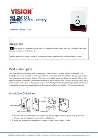
- 1. VIS_ZM1601 Wireless Siren - battery powered Firmware Version : 1.65 Quick Start A This device is a wireless Z-Wave actor. For Inclusion and Exclusion push the Tampering Switch for at least one second and release it. Please refer to the chapters below for detailed information about all aspects of the products usage. Product description The siren will warn everybody in the building by a loud sound and a flashing light about an alarm. This product is especially suited for security applications in combination with other Z-Wave devices such as door or windows sensors or motion detectors. The siren gives a loud sound and a flashing warning light, so that everybody in the building will know immediately that an alarm has occurred. The device can be configured to either use the strobe flash or the acoustic siren or both. A tamper switch protects the device from removal or manipulation if used in security applications. The device is battery powered by 4 AA standard batteries. Installation Guidelines 1. Remove the bracket from the siren by pressing the locking tab and then gently slide up the siren. Observe the correct polarity before insert the batteries. 2. Using the screws or adhesive tape to affix the bracket on the chosen location. (c) 2012 Z-Wave Europe GmbH, Goldbachstr. 13, 09337 Hohenstein-Ernstthal, Germany, All rights reserved, www.zwaveeurope.com - pp 1
- 2. 3. Slide back the cover and screw fastening with the front cover, the LED should go off. Please note: LED setting light will flash continuously in Exclusion condition. ZM1602 can only connect to DC 12~39V, AC 9~28V Power adapter. ZM1602 is extremely LOUD, please do not near your ear when you test! Behavior within the Z-Wave network I On factory default the device does not belong to any Z-Wave network. The device needs to join an existing wireless network to communicate with the devices of this network. This process is called Inclusion. Devices can also leave a network. This process is called Exclusion. Both processes are initiated by the primary controller of the Z-Wave network. This controller will be turned into exclusion respective inclusion mode. Please refer to your primary controllers manual on how to turn your controller into inclusion or exclusion mode. Only if the primary controller is in inclusion or exclusion mode, this device can join or leave the network. Leaving the network - i.e. being excluded - sets the device back to factory default. If the device already belongs to a network, follow the exclusion process before including it in your network. Otherwise inclusion of this device will fail. If the controller being included was a primary controller, it has to be reset first. Push the tampering switch for at least one seconds and release it. Operating the device Normal operation, the LED light will not be on. Self-Protection Mode: After put back the bracket over 5 seconds, ZM1601 will enter Self-Protection Mode. If the back cover is opened will trigger the Self-Protection Mode. The alarm time is default 30 seconds. User’s controller should support Z-wave FLiRS technology. Alarm Mode (It is the status of alarm triggered): It is based on the user’s configuration setting of LED flash ON/OFF and Siren ON/OFF. Note: for Default setting-Siren/Strobe Mode-Parameter will be All enable; Alarm Auto Stop Time-Parameter will be 30 sec. For safety reason, replace new battery whenever ZM1601 is triggered. Depending on the configuration settings the device will signal alarm when receiving a wireless alarm signal. Node Information Frame NI The Node Information Frame is the business card of a Z-Wave device. It contains information about the device type and the technical capabilities. The inclusion and exclusion of the device is confirmed by sending out a Node Information Frame. Beside this it may be needed for certain network operations to send out a Node Information Frame. Push the tampering switch for at least one seconds and release it. (c) 2012 Z-Wave Europe GmbH, Goldbachstr. 13, 09337 Hohenstein-Ernstthal, Germany, All rights reserved, www.zwaveeurope.com - pp 2
- 3. Configuration Parameters Z-Wave products are supposed to work out of the box after inclusion, however certain configuration can adapt the function better to user needs or unlock further enhanced features. IMPORTANT: Controllers may only allow to configure signed values. In order to set values in the range 128 … 255 the value sent in the application shall be the desired value minus 256. For example: to set a parameter to 200? it may be needed to set a value of 200 minus 256 = minus 56. In case of two byte value the same logic applies: Values greater than 32768 may needed to be given as negative values too. Siren Strobe Mode (Parameter Number 0, Parameter Size 1) defines the reaction of the siren Value Description 0 Strobe and Siren (Default) 1 Siren only 2 Strobe only Alarm auto stop (Parameter Number 1, Parameter Size 1) defines the auto time out of the alarm indication Value Description 1 60 seconds 2 120 seconds 3 no automated off 0 30 seconds (Default) Technical Data (c) 2012 Z-Wave Europe GmbH, Goldbachstr. 13, 09337 Hohenstein-Ernstthal, Germany, All rights reserved, www.zwaveeurope.com - pp 3
- 4. Battery Type 4 * AA Explorer Frame Support Yes SDK 4.54.01 Device Type Slave with routing capabilities Generic Device Class Binary Switch Specific Device Class Specific Device Class not used Routing No FLiRS No Firmware Version 1.65 (c) 2012 Z-Wave Europe GmbH, Goldbachstr. 13, 09337 Hohenstein-Ernstthal, Germany, All rights reserved, www.zwaveeurope.com - pp 4