Design and development of programmable controller for air sampling machine

Abstract A programmable Controller is designed and developed for time pedestal controlling of Air Sampling Machine. The major purpose of the designed system is to reduce filter damage of Air Sampling Machine. The main function of the controller is to automatically switching the Air Sampling Machine with predefined On-Off time interval for 24 hours operation. This is a low cost system which is designed using locally available components and user friendly. The controlling operation is maintained by ATMEL AT89C52 microcontroller. A programmable real time clock PCF8583 is used to produce timing control signal for automatic switching of the Air Sampling Machine. Control signals generated by real time clock operate opto-isolator and an electromechanical relay for switching the Air Sampling Machine. EEPROM (M24C64) is used to store necessary data. The instruction firmware for the designed controller has been developed in BASIC platform using BASCOM-8051 software. The designed system is functioning properly and serving the purpose of the design. Keywords: Programmable Controller, AT89C52 microcontroller, RTC, EEPROM, I2C Protocol, BASCOM-8051 IDE

Recommandé
Recommandé
Contenu connexe
Tendances
Tendances (20)
Similaire à Design and development of programmable controller for air sampling machine
Similaire à Design and development of programmable controller for air sampling machine (20)
Plus de eSAT Journals
Plus de eSAT Journals (20)
Dernier
Dernier (20)
Design and development of programmable controller for air sampling machine
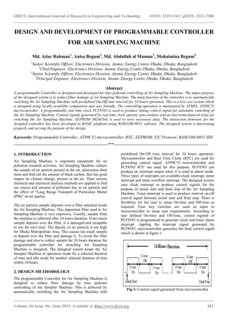
- 1. IJRET: International Journal of Research in Engineering and Technology eISSN: 2319-1163 | pISSN: 2321-7308 _______________________________________________________________________________________ Volume: 04 Issue: 06 | June-2015, Available @ http://www.ijret.org 257 DESIGN AND DEVELOPMENT OF PROGRAMMABLE CONTROLLER FOR AIR SAMPLING MACHINE Md. Atiar Rahman1 , Anisa Begum2 , Md. Abdullah al Mamun3 , Mohaimina Begum4 1 Senior Scientific Officer, Electronics Division, Atomic Energy Centre Dhaka, Dhaka, Bangladesh 2 Chief Engineer, Electronics Division, Atomic Energy Centre Dhaka, Dhaka, Bangladesh 3 Senior Scientific Officer, Electronics Division, Atomic Energy Centre Dhaka, Dhaka, Bangladesh 4 Principal Engineer, Electronics Division, Atomic Energy Centre Dhaka, Dhaka, Bangladesh Abstract A programmable Controller is designed and developed for time pedestal controlling of Air Sampling Machine. The major purpose of the designed system is to reduce filter damage of Air Sampling Machine. The main function of the controller is to automatically switching the Air Sampling Machine with predefined On-Off time interval for 24 hours operation. This is a low cost system which is designed using locally available components and user friendly. The controlling operation is maintained by ATMEL AT89C52 microcontroller. A programmable real time clock PCF8583 is used to produce timing control signal for automatic switching of the Air Sampling Machine. Control signals generated by real time clock operate opto-isolator and an electromechanical relay for switching the Air Sampling Machine. EEPROM (M24C64) is used to store necessary data. The instruction firmware for the designed controller has been developed in BASIC platform using BASCOM-8051 software. The designed system is functioning properly and serving the purpose of the design. Keywords: Programmable Controller, AT89C52 microcontroller, RTC, EEPROM, I2C Protocol, BASCOM-8051 IDE -------------------------------------------------------------------***------------------------------------------------------------------- 1. INTRODUCTION Air Sampling Machine is important equipment for air pollution research activities. Air Sampling Machine collects the sample of air particle present in the air, determines their mass and find out the amount of black carbon, that has great impact on climate change, present in the air. Then various chemical and statistical analysis methods are applied to find out source and amount of pollutant due to air particle and the effect of “Long Range Transport of Particulate Matter (PM)” on air quality. The air particle sample deposits over a filter attached inside the Air Sampling Machine. This deposition filter used in Air Sampling Machine is very expensive. Usually, sample from the machine is collected after 24 hours duration. If too much sample deposits over the filter, it is damaged and incapable to use for next time. The density of air particle is too high for Dhaka Metropolitan Area. This causes too much sample to deposit over the filter and damage it. To avoid the filter damage and also to collect sample for 24 hours duration the programmable controller for switching Air Sampling Machine is designed. The designed system keeps the Air Sampler Machine in operation mode for a selected duration of time and idle mode for another selected duration of time within 24 hours. 2. DESIGN METHODOLOGY The programmable Controller for Air Sampling Machine is designed to reduce filter damage by time pedestal controlling of Air Sampler Machine. This is achieved by automatically switching the Air Sampling Machine with predefined On-Off time interval for 24 hours operation. Microcontroller and Real Time Clock (RTC) are used for generating control signal. AT89C52 microcontroller and PCF8583 RTC are used for this purpose. PCF8583 can produce an interrupt output when it is used in alarm mode. Three types of interrupts are available-clock interrupt, timer interrupt and timer overflow interrupt. The designed system uses clock interrupt to produce control signals for the purpose of initial start and final stop of the Air Sampling Machine. Timer interrupt is used to produce interval on-off control signal between initial start and final stop. There is flexibility for the user to setup On-time and Off-time as required. Four key switches are used as input to microcontroller to setup user requirements. According to user defined On-time and Off-time, control register of PCF8583 is programmed to generate clock and timer alarm interrupt. Appling the interrupt signal generated by PCF8583, microcontroller generates the final control signal which is shown in figure 1. Fig-1: Control signal generated from microcontroller
- 2. IJRET: International Journal of Research in Engineering and Technology eISSN: 2319-1163 | pISSN: 2321-7308 _______________________________________________________________________________________ Volume: 04 Issue: 06 | June-2015, Available @ http://www.ijret.org 258 Inter-Integrated Circuit (I2C) protocol is used for communication between microcontroller and RTC. The I2C- bus is for bidirectional, two-line communication between different ICs or modules. The two lines are a serial data line (SDA) and a serial clock line (SCL). Both lines must be connected to a positive supply via a pull-up resistor. Data transfer may be initiated only when the bus is not busy. I2C communication occurs in Master-Slave mode. The device that controls the message is the „master‟ and the devices which are controlled by the master are the „slaves‟. Master- Slave configuration is shown in figure 2. Fig-2: System Configuration Both data and clock lines remain HIGH when the bus is not busy. A HIGH-to-LOW transition of the data line, while the clock is HIGH is defined as the start condition (S). A LOW- to-HIGH transition of the data line while the clock is HIGH is defined as the stop condition (P). Fig-3: Start and Stop condition of I2C communication One data bit is transferred during each clock pulse. The data on the SDA line must remain stable during the HIGH period of the clock pulse as changes in the data line at this time will be interpreted as a control signal. Changes in data are allowed only during LOW period of the clock pulses. Fig-4: Bit Transfer of I2C communication 3. HARDWARE DESIGN The rapid and revolutionary progress in power electronics and microelectronics in recent years has made it possible to apply modern control technology for controlling electronic equipment. Automatic control system reduces human doings and save money. Block diagram of the designed programmable controller for Air Sampling Machine is presented in figure 5. Fig-5: Block diagram of programmable Controller for Air Sampling Machine. 3.1 Power Supply Unit: Main function of the power supply unit is to convert 220v ac voltage to 5 volt dc voltage. Power supply unit consists of Step-down Transformer, Bridge Rectifier and Positive Voltage Regulator. 5 volt output of power supply unit is used by microcontroller, I2C Devices (RTC & EEPROM), Optoisolator, Relay and LCD Display. 3.2 Microcontroller Unit: This is the heart of the designed system. AT89C52 microcontroller is used to control all functionality of the designed system. The AT89S52 is a low-power, high- performance CMOS 8-bit microcontroller with 8K bytes of in-system programmable Flash memory. This is a powerful microcontroller which provides a highly-flexible and cost- effective solution to many embedded control applications. The AT89S52 provides the following standard features: 8K bytes of Flash, 256 bytes of RAM, 32 I/O lines, Watchdog timer, two data pointers, three 16-bit timer/counters, a six- vector two-level interrupt architecture, a full duplex serial port, on-chip oscillator, and clock circuitry. 3.3 RTC Unit: PCF8583 is a real time clock which is used in the designed system to provide real time clock and also to generate switching control signal of Air Sampler Machine. The PCF8583 is a clock/calendar circuit based on a 2048-bit static CMOS RAM organized as 256 words by 8 bits. Addresses and data are transferred serially via the two-line
- 3. IJRET: International Journal of Research in Engineering and Technology eISSN: 2319-1163 | pISSN: 2321-7308 _______________________________________________________________________________________ Volume: 04 Issue: 06 | June-2015, Available @ http://www.ijret.org 259 bidirectional I2C-bus. PCF8583 provides three types of interrupts – Clock alarm, timer alarm and timer overflow alarm interrupts. PCF8583 has an active low interrupt output which is activated during the occurrence of alarm function of any type. In this designed system, clock alarm is used in 24 four hour mode to provide initial start and final stop signal and Timer alarm is used to provide interval On-Off control signal between the initial start and final stop. 3.4 EEPROM Unit: M24C64 is used as EEPROM to store necessary data of the designed system. This device is compatible with the I2C memory protocol. This is a two wire serial interface that uses a bi-directional data bus and serial clock. The device behaves as a slave in the I2C protocol, with all memory operations synchronized by the serial clock. Read and Write operations are initiated by a Start condition, generated by the bus master. 3.5 Optoisolator and Relay Unit: There are many situations where signals and data need to be transferred from one subsystem to another within a piece of electronics equipment, or from one piece of equipment to another, without making a direct ohmic electrical connection. Often this is because the source and destination are (or may be at times) at very different voltage levels, like a microprocessor which is operating from 5V DC but being used to control a triac which is switching 240V AC. In such situations the link between the two must be an isolated one, to protect the microprocessor from over voltage damage. The control signal generated from the microcontroller is used to operate the optocoupler which gives an output signal that is used to operate an electromechanical relay for the purpose of switching the Air Sampling Machine. 3.6 Display Unit: A LCD is attached with the designed system to make visual interface for the user. The circuit diagram of the programmable controller for Air Sampling Machine is presented in figure 6. FILE NAME: BY: DATE: PAGE: ASM Controller.DSN 11/5/2014 <NONE> A B C D E F G H J K A B C D E F G H J K 0 1 2 3 4 5 6 7 8 9 0 1 2 3 4 5 6 7 8 9D:Paper2014ASM ControllerCircuitASM Controller.DSNPATH: 1 of 1 REV:<NONE> TIME: 4:27:48 PM DESIGN TITLE: ASM CONTROLLER XTAL2 18 XTAL1 19 ALE 30 EA 31 PSEN 29 RST 9 P0.0/AD0 39 P0.1/AD1 38 P0.2/AD2 37 P0.3/AD3 36 P0.4/AD4 35 P0.5/AD5 34 P0.6/AD6 33 P0.7/AD7 32 P1.0/T2 1 P1.1/T2EX 2 P1.2 3 P1.3 4 P1.4 5 P1.5 6 P1.6 7 P1.7 8 P3.0/RXD 10 P3.1/TXD 11 P3.2/INT0 12 P3.3/INT1 13 P3.4/T0 14 P3.7/RD 17 P3.6/WR 16 P3.5/T1 15 P2.7/A15 28 P2.0/A8 21 P2.1/A9 22 P2.2/A10 23 P2.3/A11 24 P2.4/A12 25 P2.5/A13 26 P2.6/A14 27 U1 AT89C52 C2 22p C1 22p X1 CRYSTAL C3 12p R1 1k 6 5 4 1 2 U8 OPTOCOUPLER-NPN R17 220 RST RST XTAL1 XTAL2 XTAL1 XTAL2 D7 14 D6 13 D5 12 D4 11 D3 10 D2 9 D1 8 D0 7 E 6 RW 5 RS 4 VSS 1 VDD 2 VEE 3 LCD1 LM044L P1.2 P1.3 P1.4 P1.5 P1.6 P1.7 P1.6 P1.7 P1.5 P1.4 P1.3 P1.2 R4 R5 R6 R7 KEY1 KEY2 KEY3 KEY4 P2.0 P2.1 P2.2 P2.3 P2.3 P2.2 P2.1 P2.0 SCL 6 SDA 5 WC 7 E0 1 E1 2 E2 3 U3 M24C64 Vout SCL 6 SDA 5 A0 3 INT 7 OSCI 1 OSCO 2 U4 PCF8583 R8 10k C7 30p X2 CRYSTAL INT R9 4k7 R10 4k7 R11 100k INT/P2.7 INT/P2.7 SDA/P3.6 SCL/P3.7 SDA/P3.6 SCL/P3.7 RL1 NTE-R46-12 Q1 2N2219 D3 1N4006 R1 4.7k R3 1k 1 2 J3 CONN-SIL2 To Instrument P2.6 P2.6BR1 W005G 1 2 J1 CONN-SIL2 Transformer From VI 1 VO 3 GND 2 U1 7812 VI 1 VO 3 GND 2 U2 7805 C2 10p C3 100u C4 10p C8 10p C1 10u 12VDC 12V DC POWER UNIT SWITCHING UNIT MICROCONTROLLER UNIT RTC & EEPROM Fig-6: Circuit diagram of programmable Controller for Air Sampling Machine.
- 4. IJRET: International Journal of Research in Engineering and Technology eISSN: 2319-1163 | pISSN: 2321-7308 _______________________________________________________________________________________ Volume: 04 Issue: 06 | June-2015, Available @ http://www.ijret.org 260 4. SOFTWARE DESIGN Bascom-8051 IDE is used to write program describing the functionality of the designed system. This a powerful tool developed by MCS electronics to build up firmware for AT89-series microcontroller. All instructions for program development are well defined in BASCOM-8051 user manual. The whole working Algorithms for designing the software are summarized in the flowcharts shown in Figures 7, 8 and 9. Flowchart shown in figure-7 describes the step by step operation of the designed system. Figure-8 shows the flowchart describing the process of setting real time clock. The same procedure is used to set clock alarm form which microcontroller will start switching operation for 24 hours duration. After 24 hours from the time programmed by clock alarm, microcontroller will stop switching operation. Within 24 hours interval On-Off time need to set for continuing interval switching operation. Flowchart in figure-9 describes the process of On-Time and Off-Time setting for interval switching of Air Sampling Machine. Fig-7: Flowchart of the designed system part-1 Fig-8: Flowchart of the designed system part-2 Fig-9: Flowchart of the designed system part-3 5. OPERATIONAL DESCRIPTION: Figure 10 shows the designed Programmable Controller attached with Air Sampling Machine.
- 5. IJRET: International Journal of Research in Engineering and Technology eISSN: 2319-1163 | pISSN: 2321-7308 _______________________________________________________________________________________ Volume: 04 Issue: 06 | June-2015, Available @ http://www.ijret.org 261 Fig-10: Designed Controller attached with Air Sampling Machine Four key switches are involved to setup user requirements, 1. Mode key “MOD”, 2. Increment Key “INCR”, 3. Decrement Key “DCR” and 4. Enter Key “ENTR” User should press MOD key to enter different operational mode of the designed system. After entering in desired mode, user should use INCR, DCR and ENTR keys to set up desired requirements. Various operational mode of the designed controller are: 1. Normal Mode: This mode displays default Date and Time (figure 11) but when the controller is in running condition this mode displays present date and time in addition with on-off status of the switching equipment i.e. Air Sampling Machine(figure 12). Fig 11: Normal mode Fig 12: Normal mode in running condition 2. SET CLOCK mode: In this mode user can set present date and time using Increment, Decrement and Enter Key. Fig13: Set Clock Mode 3. SET START TIME mode: In this mode user can set initial start time using Increment, Decrement and Enter Key from which the Air Sampling Machine start initially and will stop finally after 24 hours of the initial start. Actually, this is similar to set Clock Alarm Mode. Fig 14: Set Clock Alarm Mode 4. SET ON/OFF TIME mode: In this mode user can set Interval On-Time and Off-Time using Increment, Decrement and Enter. Fig 15: Set ON/OFF Time Mode 5. SHOW START TIME mode: This mode displays START time and ON/OFF time consigned by user. Fig 16: SHOW START TIME Mode
- 6. IJRET: International Journal of Research in Engineering and Technology eISSN: 2319-1163 | pISSN: 2321-7308 _______________________________________________________________________________________ Volume: 04 Issue: 06 | June-2015, Available @ http://www.ijret.org 262 6. RUN mode: In this mode user should press ENTER KEY to enter the controller in operational mode. When Enter Key is pressed the Controller display “RUNNING” indicating that the controller is now in operational mode. Fig 17: System is running 7. ON/OFF RECORD mode: In this mode user should press ENTER KEY to see ON/OFF records. Three records are shown at a time. Press Enter key again to see next three records and so on. Fig 18: On-Off Records 8. STOP mode: In this mode, if the controller is in “RUNNING” condition then the user should press ENTER KEY to manually stop the controlling action. Fig 19: Manual Stop by User 6. CONCLUSION The programmable controller for air sampling machine has been developed and is tested by controlling interval ON- OFF switching of Air Sampling Machine. It is working well by switching the Air Sampling Machine by user defined on- off time within 24 hours duration. Low productive cost, easy operation and good performance of the system make the system more significant. It reduces cost in air pollution research activities by preventing unexpected filter damage. The controller we have designed is not only for the Air Sampling Machine, it can also be used for machines and electronic equipments which need time based start and stop. At the same time it can be used as data logger. In future the designed system will be upgraded with GSM module to send ON-OFF status to the user. REFERENCES [1]. The 8051 Microcontroller and Embedded Systems (sixth edition) by M.A. Mazidi and J.G. Mazidi [2]. Electronics Devices and Circuit Theory by R.L Boylestad, L, Nashelsky and K.L Kishore [3]. Electronics Devices (Sixth edition) by Thomas L. Floyd [4]. RS Components (International Edition November 1991- February 1992) [5]. “Design &Implementation of I2C Master Controller Interfaced With RAM Using VHDL” by Sansar Chand Sankhyan, published on Int. Journal of Engineering Research and Applications [6]. Wikipedia Link on I2C Communication http://en.wikipedia.org/wiki/I%C2%B2C [7]. Sam Fleming; “Interfacing I2C Device to an Intel SMBUS Controller” Intel Corporation Jan 2009 [8]. Thomas Kugelstadt; “Designing an isolated I2C Bus interfacing using Digital isolator”, analog application Journal 2011 [9]. White Paper on “Accessing the Real Time Clock Registers and the NMI Enable Bit”, by Sam Fleming Technical Marketing Engineer Intel Corporation [10]. Datasheets of PCF8583 [11]. ATMEL Corporation “Interfacing Serial EEPROM to microcontroller” 2001 [12]. Datasheets of M24C64 [13]. Datasheets of AT89C52 BIOGRAPHIES Md. Atiar Rahman has completed graduation from University of Rajshahi, Bangladesh in Applied Physics and Electronics Engineering. Presently he is working as a Senior Researcher in the field of Electronics at Bangladesh Atomic Energy Commission. Anisa Begum has completed graduation from Bangladesh University of Engineering & Technology in EEE. Currently she is working as chief engineer & director, HRD, Bangladesh Atomic Energy Commission. Md. Abdullah Al Mamun has completed graduation from University of Dhaka, Bangladesh in Applied Physics, Electronics & Communication Engineering. Presently he is working as a Senior Researcher in the field of Electronics at Bangladesh Atomic Energy Commission.
- 7. IJRET: International Journal of Research in Engineering and Technology eISSN: 2319-1163 | pISSN: 2321-7308 _______________________________________________________________________________________ Volume: 04 Issue: 06 | June-2015, Available @ http://www.ijret.org 263 Mohimina Begum has completed graduation from Institute of Engineers, Bangladesh in Electrical Engineering. Presently she is working as a Principal Researcher in the field of Electronics at Bangladesh Atomic Energy Commission. hor’s Photo