SlideShare une entreprise Scribd logo
1  sur  109
Télécharger pour lire hors ligne
Symmetrix Configuration Management
With virtual LUN and an internal migration in the same storage, we can move from FC to SATA,
SSD, etc disks.

E20-335 certificacion de symm sol specialist. Faltaria el de symmetrix bussiness continuity
management y puedo certificar.

DMX Architecture Overview:


The Symmetrix V-Max system uses Engine-based packaging containing Front End, Back End and
memory components. The Symmetrix V-Max system implements a virtual matrix interconnect,
enabled by a new version of Enginuity. As the table shows, the new architecture enables
significant increases in scalability. Scalability has improved in all aspects: Front End connectivity,
Global Memory, Back End connectivity and usable capacity.
Let’s take a closer look at the Virtual Matrix Architecture. Symmetrix V-Max Series with Enginuity
is built around a scalable Virtual Matrix interconnect design.

The Virtual Matrix is redundant and dual active and supports all Global Memory references, all
messaging, and all management operations including internal discovery and initialization, path
management, load balancing, fail over, and fault isolation within the array.

The Symmetrix V-Max array is comprised of 1 to 8 V-Max Engines. Each V-Max Engine contains
two integrated directors. Each director has two connections to the V-Max Matrix Interface Board
Enclosure (MIBE) via the System Interface Board (SIB) ports.
Since every director has two separate physical paths to every other director via the Virtual Matrix,
this is a highly available interconnect with no single point of failure.

This design eliminates the need for separate interconnects for data, control, messaging,
environmental and system test. A single highly-available interconnect suffices for all
communications between the directors, which reduces complexity.

The denomination SE (or Single Engine) is for a base VMAX that cannot be upgraded, opposed to
the normal VMAX that no matter it is sold with a single engine, it can be upgraded and receive
multiple engines later.

Each director has two communications ports to the internal virtual matrix. Each director can
communicate with the other directors, throught theseports. An i/o might be reeived by one
engine, stored in the cache of another engine, and written to the drive by still another engine.
In the following graphic, you can see the diretor, joined by the VMAX virtual matrix above,
sharing its global cache memory.
The key data processing components of a Symmetrix V-Max array are engines. A full-sized array
can have up to eight engines. Each engine has two directors that service I/O requests from hosts
and the disk drives. V-Max directors are similar to DMX directors, however they have twice as
many ports.

Each director has four independent slices. Each slice manages two to four external host ports or
four internal drive ports.

Each engine is a self-contained module with its own power supplies, batteries, environmental
monitors, and internal and external I/O ports. Each director has connections to two independent
virtual matrices. This lets the directors communicate and share in the I/O handling—an I/O
processed by one director might be stored on drives managed by other directors.

Each V-Max engine also has a global cache area. As you add engines, you increase the amount of
cache in the array. It is considered to be global because any engine can access any other
engine’s cache memory. All I/O into or out of the array is cached in memory.

Each director has two communications ports to the internal virtual matrix. Each director can
communicate with the other directors through these ports. An I/O might be received by one
engine, stored in the cache of another engine, and written to the drive by still another engine.


Host I/O operation are managed by the Enginuity operating environment, which runs in the
Symmetrix I/O subsystem (channel directors and disk directors). Because each of the physical
disks are indirectly seen as part of the I/O protocol, Symmetrix devices are presented to the host
with the following configuration or emulation attributes:

Maximum Volume size that can be configured on a V-Max is 262668 cylinders. If host
applications require larger volumes, multiple volumes can be combined to form a metavolume.
 Each device has N cylinders. The number is configurable (blocks ÷ 960)
Each cylinder has 15 tracks (heads)
 Each device track in a fixed block architecture (FBA) has 128 blocks of 512 bytes (64K)
Note: prior to DMX3, the track size for FBA devices was 32K
 Mainframe hosts use Count Key Devices (CKD) uses variable block sizes.
The Symmetrix is configured using a static configuration file called the IMPL.bin. The file is
created initially using the SymmWin software from the Service Processor and loaded into each
director in the Symmetrix. When modifying a configuration, the current IMPL.bin file is pulled
from the Symmetrix and edited use Symmwin.

SymmWin is an EMC written graphical-based application for managing a Symmetrix. Capabilities
include:

 Building and modifying system configuration files (IMPL.bin)
 Issuing Inlines commands, diagnostic, and utility scripts
 Monitoring performance statistics
 Automatically performs periodic error polling for errors and events. Certain errors will cause
the service processor to “Call Home”.

SymmWin runs locally on a Symmetrix Service Processor or on a standalone PC. Running on the
service processor allows communications with an operational Symmetrix. Running it on a
standalone system allows you to build a new configuration or view and modify an archived
configuration file.

EMC’s Solution Enabler APIs are the storage management programming interfaces that provide
an access mechanism for managing the Symmetrix. They can be used to develop storage
management applications. SYMCLI resides on a host system to monitor and perform control
operations on Symmetrix arrays. SYMCLI commands are invoked from the host operating system
command line (shell). The SYMCLI commands are built on top of SYMAPI library functions, which
use system calls that generate low-level I/O SCSI commands to the storage arrays.


The SYMCLI configuration change command, symconfigure, is used to perform control operations
on Symmetrix arrays and the array devices and ports. Some of the Symmetrix array controls
include setting how many hypers per disk are allowed, and what type of devices the array will
support, such as RAID 6 devices. Device controls include creating devices, mapping and masking
devices, and configuring device pools. The symconfigure command is also used for reserving
devices and releasing device reservations.


To reduce the number of inquiries from the host to the storage arrays, configuration and status
information is maintained in a Symmetrix host database file called the Symmetrix configuration
database (default file name: symapi_db.bin).

The SYMCLI Configuration Change Component, frequently referred to as the Config Manager is
invoked using the symconfigure command. It can also be invoked through the Symmetrix
Management Console GUI.

Config Manager is capable of configuration operations in the Symmetrix. A few SRDF related
configuration activities cannot be performed by Config Manager. These include:

•Dynamic RDF group and pair creation and deletion which can be done with the symrdf
command

•Modification of dynamic RDF group parameters such as Prevent Automatic RDF Link
Recovery which can be set using the symrdf command

•Modify the RAs online upon Power On parameter which has to be set through the
Symmetrix Service Processor using Symwin.
The Config Manager architecture allows it to run Symwin scripts on the Symmetrix service
processor.

Configuration change requests are generated either by the symconfigure SYMCLI command or a
SYMAPI library call generated by a user making a request through the Symmetrix Management
Console (SMC) GUI.

These requests are converted by SYMAPI on the host to Symmetrix syscalls and transmitted to
the Symmetrix through the channel interconnect. The Symmetrix front end routes the requests to
the service processor, which invokes Symmwin procedures to perform the requested changes to
the Symmetrix.

Since these scripts are the same ones that a Customer Services Engineer would employ to
configure the Symmetrix, Config Manager is able to do almost everything that is possible through
Symwin scripts.

Note: The communication between storage devices has the purpose of replication and internal
commands, hence is better to have a local symcli / solutions enabler client connected by
gatekeepers to each storage instead of using it “remotely”, by the interstorage link.

Operation Classes:

   Array Wide Operations
   Device Operations
   Metadevice Operations
   Device Mapping
   Device Pool Management
   RDF Configuration (Older Symmetrix Arrays)
   RDF Group parameters
   Front-end port attributes
Configuration Manager operations can be divided into several classes.
A detailed listing of the actions available under each class is described in the Symmetrix Array
Controls Guide.

Array wide operations allow the setting of Symmetrix metrics.

Device operations comprise creation and deletion of devices, modification of device attributes and
binding and unbinding of Thin devices to pools.

Metadevice operations allow the formation and dissolution of metavolumes.

Mapping makes a device available to a Symmetrix front-end port.

Device pools operations allow for the management of Thin pools, Snap pools and SRDF DSE
pools.

RDF Configuration actions are more meaningful with the older Symmetrix arrays where static
RDF groups are more prevalent.

RA group parameters relate to RDF/A groups and DSE pools for SRDF/A.

Front-end port attributes are set to cater to the needs of different vendors’ operating systems.

Before making configuration changes, it is important to know the current Symmetrix
configuration.

Verify that the current Symmetrix configuration is a viable configuration for host-initiated
configuration changes.

The command:                     symconfigure verify -sid SymmID

will return successfully if the Symmetrix is ready for configuration changes

Free physical disk space can be checked using the command:

symconfigure list -freespace [-units CYLINDERS|MB] -sid SymmID

Use protected devices for storing data. Check the product documentation to understand the
impact that a configuration change operation can have on host I/O.

Configuration change requests are placed in a command file. The syntax for these commands is
described in Chapter 1 of the Symmetrix Array Control CLI Product Guide.

Prior to Enginuity 5669 only one class of commands could be submitted for execution at one
time.

Though that restriction does not exist today any more, changes to dynamic RDF, Save pools and
protected expansion of striped metavolumes can still not be mixed with other class operations in
the same command file.
Before 5874 a configuration change request acquired Symmetrix lock 15 and prevented other
changes from being made until the first was completed. In 5874 configuration changes need not
be done one at a time.

In 5874 a change operation only takes the resources it needs to do its job. The old locks 15 and
9 have been replaced with four separate locks described later. The new locks reserve system
resources with greater granularity and for shorter duration on the Symmetrix V-Max. With
Solutions Enabler 7.0 on a DMX running 5773 or earlier, locks will still be taken one at a time and
no parallelism is allowed.

Configuration Locks in 5874:

This information shown here is not exposed to the user and hence not documented in the
product guide. There are four kinds of locks that can be taken during a configuration change
session. The granularity of the locks allow operations that do not take the same locks to run in
parallel.

Director locks are taken by changes when a director is affected. A mapping operation will lock the
director to which a device is being mapped. However, a different device being mapped to a
different director will not take the same locks and could therefore be mapped in parallel.

The front end device lock is taken when the front end of the device, such as meta-formation or
device mapping is being undertaken.

The backend device lock is taken when the back end is being affected. An Optimizer swap affects
the back end only.

Changes that require a reloading of the IMPL.bin file take the static configuration lock.. This lock
prevents other configuration changes that require IMPL changes. Other configuration changes
can happen concurrently if they need device locks or director locks.
There is a CE Config Lock, that is set from the Service Processor, that acts like the old lock 15. It
prevents any other configuration changes from happening on the Symmetrix.
In the example shown a group of devices being mapped to a director takes the front end lock
for the devices involved and a lock on the director to which the devices are being mapped.
A device creation operation takes the static configuration lock, the device front and back end
locks for the devices being created. Since the devices being created are not the ones being
mapped, the two changes can occur in parallel.

If however, the device creation step also included a mapping step that mapped the newly
created devices to the same director to which the first set of devices are being mapped, the two
actions could not happen in parallel.

On the right hand side are two hosts competing for the same front end director port. As a result
one of the hosts that issues the second request for the front end director resources will fail to
complete the change.


Configuration change sessions can be viewed using the symconfigure query command. If there
are multiple sessions running all session details are shown.
In rare instances, it might become necessary to abort configuration changes. This can be done
with the symconfigure abort command as long as the point of no return has not been reached.
Aborting a change that involves RDF devices in a remote array might necessitate the termination
of changes in a remote array.

# symconfigure -sid 207 -session_id 39682 abort -noprompt
A Configuration Change abort is in progress. Please wait...
A Configuration Change operation is in progress. Please wait...
Looking for an existing configuration session.............Established.
The session changes are in the class of: Creating new symdevices
{
create dev count=1, size=2200 cyl, emulation=FBA, config=2-Way Mir,mvs_ssid=a;
}
The Application that initiated the configuration change : SYMCONFIGURE
The Host that initiated the configuration change             : api1051
The Process ID that initiated the configuration change : 12382
The session length                                 : 18 secs
Aborting configuration changes............................Aborted.
Terminating the configuration change session..............Done.
The configuration change session has been aborted.


A Symmetrix can have over 64000 devices configured. Not all devices are accessed by every
front-end port. Instead, specific devices are “mapped” to specific ports by assigning a channel
address. Host systems discover and access Symmetrix devices using these Channel Addresses.
For open systems hosts, the Channel address is the SCSI ID. Normally a host uses a combination
of the Controller, Target, and Logical Unit Number to address a disk device. The Controller
number is the Host Bus Adapter, the Target is the port on the Storage System and the Logical
Unit Number is the Channel Address we assign.
The reverse of mapping a device is unmapping a device. Unmapping can become necessary prior
to a device being converted from one type to another e.g. a standard to a meta member. Before
the device is unmapped it has to be set not ready. The unmap action will fail if the device is R/W
enabled.


Before connecting an open systems host to the Symmetrix the following questions should be
answered:

 Which host is going to connect to which port.
 What are the operating systems and versions of the hosts.
 Number, type, and firmware levels for Host Bus Adapters (HBA).
 Is PowerPath or other multi-pathing failover software used.
 How many, what protection, what size volumes are required.
 Performance considerations (e.g. faster disks should be picked for high performance
applications).

On the host side, the host bus adapter (HBA) has to be configured with the correct drivers. Multi-
pathing software if present needs to be set up on the host.
The physical SAN connection between the host and the Symmetrix consists of cables and SAN
equipment such as Fibre channel switches. Logical zones are needed to establish a connection
between the host bus adapter and the Symmetrix front end ports.

On the Symmetrix side the front end adapter (e.g. FA) needs to be cabled to the SAN and zoned
such that the host HBA and the front end adapter (e.g. FA) are in the same zone. Zoning can be
done using software from the SAN vendors.

The characteristics of the front end adapter port, to which the HBA connects, need to be
appropriately set so the host operating system can access the Symmetrix devices. Device
mapping permits a device to be accessible through a front end port. Config Manager is the
appropriate tool to perform both of these tasks..

Device masking permits only a subset of devices that are mapped to a port to be visible to an
HBA. This feature allows multiple hosts to share the same Symmetrix front end port without
encroaching on another host’s devices. Device masking is performed using the masking
commands in Solutions Enabler symmask and symmaskdb.


Storage Area Networks provide a fan-out capability where it is likely that more than one host is
connected to the same Symmetrix port. The actual number of HBAs that can be configured to a
single port is operating system and configuration dependent but fan-out ratios as high as 256:1
are currently supported. Reference the support matrix for specific configuration limitations.

When several hosts connect to a single Symmetrix port, an access control conflict can occur
because all hosts have the potential to discover and use the same storage devices. However, by
creating entries in the Symmetrix’s device masking database (VCMDB), it is possible to control
the volumes “seen” by a host.

Device Masking is independent from zoning but zoning and masking are typically used together in
an environment. Zoning provides access control at the port level. It establishes a logical
connection between the host bus adapter and port on the storage system. Device masking allows
a subset of volumes mapped to a port to be visible to the host bus adapter.

With Fibre Channel, Device Masking uses the UWWN (Unique Worldwide Name) of Host Bus
Adapters and a VCM database device. In iSCSI, the iSCSI Qualified Name (IQN) is used.
Regardless of the protocol, the concepts are the same. The device-masking database (VCMDB)
on each Symmetrix unit specifies the devices that a particular WWN or IQN can access through a
specific Fibre port.
The Volume Logix Database persistently maintains the device masking information. Originally the
database was located directly on a Symmetrix Logical Volume. On DMX-3 it is maintained in the
Symmetrix File System (SFS). Rather than create the actual VCMDB device, today we create a
VCM Gatekeeper device which is used by the Solutions Enabler to access the database on the
SFS, as the SFS volumes are not host addressable. The VCM Gatekeeper is a 6-cyl device.

By default, the device masking VCMDB is accessible to all HBAs that log into the director port
where the database is configured. Thus, any host with access privileges can effectively modify
the contents of the database if it has device masking commands are installed. Beginning with
Enginuity Version 5670, the VCMDB can be unmapped from any director that is not being used
for masking control.

This database, “VCMB” is now in a disk, with the SFS (symmetrix file system), the same as
aclx/aclxdb. It is always recommended to run a symmaskdb –sid xx backup –f ‘backup.bkb’
before doing a config change and a symmask –sid xx refresh after it.

Device Masking controls host access to a set of devices by maintaining a set of entries in the
VCMDB on the array that defines the relationship between masked connections and devices.
These entries are sometimes called initiator records.

Each entry includes a host's HBA identity (WWN or iSCSI Qualified Name), its associated FA port,
and a range of devices mapped to the FA port that should be visible only to the corresponding
HBA.

Once you make this VCMDB entry and activate the configuration, the Symmetrix makes visible to
a host those devices that the VCMDB indicates are available to that host's initiator through that
FA port.
Volume Logix is the brand name for the software in the Symmetrix that performs the device
masking function. The capability is built into Enginuity but its use is optional.


An Initiator Group contains the world wide name or iSCSI name of a host initiator, also referred
to as an HBA or host bus adapter. An initiator group may contain a combination of up to thirty-
two, Fibre Channel initiators or eight, iSCSI names or a combination of both. There is a limit of
eight thousand one hundred ninety-two, (8,192) initiator groups in a Symmetrix V-Max array.
Port flags are set on an initiator group basis, with one set of port flags applying to all initiators in
  the group. However the FCID lockdown is set on a per initiator basis. An individual initiator can
  only belong to one Initiator Group.

  However once the initiator is in a group, the group can be a member in another initiator group. It
  can be grouped within a group. This feature is called cascaded initiator groups, and is only
  allowed to a cascaded level of one.

  A Port Group may contain any number of valid front end ports, FAs. Front end ports may belong
  to more than one port group. There is a limit of five hundred twelve (512) port groups. Before a
  port can be added to a port group the ACLX flag must enabled on the port.

  A Storage Group may contain up to four thousand ninety-six, (4,096) Symmetrix logical volumes.
  A logical volume may belong to more than one storage group. There is a limit of eight thousand
  one hundred ninety-two, (8,192) storage groups.


  Each Symmetrix logical volume is allowed up to 4 mirrors. Prior to Enginuity 5874, local mirrors
  and parity RAID mirrors would occupy a second mirror position. This limited the number of
  remote mirrors and TimeFinder/Mirror BCVs these volumes could be joined to.

  In 5874, TimeFinder/Mirror is no longer supported. Remote mirrors still occupy a mirror position
  but local mirrors no longer occupy a mirror position. Thus the 4 mirror limit is no longer a limiting
  factor.

  Apart from unprotected devices, which are not recommended, Symmetrix volumes can be
  configured with RAID-1, RAID-5 or RAID-6 protection.

 BCVs are device types that are used for local replication.
 RDF volumes are used for remote replication.
 Virtual devices are used in TF/Snap. They are cache only devices and do not consume disk space.
 Thin Devices are used for Virtual provisioning. They are cache only devices and do not consume
disk space.
 Diskless devices are used for cascaded R21s. They are cache only devices and do not consume
disk space.
 Save and Data devices hold the actual data for Virtual and Thin devices respectively.
 Each of these devices can be created with the Configuration manager. Less commonly used
devices, such as DRV devices have not been listed above.


                                                             
                                                             VDEV + SAVE are used by TF/SNAP.

                                                             
                                                             TDEV + DATA are used by Virtual
                                                             provisioning.

                                                             
                                                             Diskless device = R21, it is a
                                                             position in memory used for
                                                             cascaded SRDF.
Once the four slots used as mirror positions, there cannot be another operation with the device
(IE RAID1 uses 2 positions, TF mirror uses one, and SRDF uses another one) hence, no
operations left to be done. If TF Clone is used, then 3 positions from the new device are free to
use. An spare could not be involed in the four positions are used. VMAX uses only one position in
RAID1, leaving one position free to use. (RVA as named before)


In the command file, you can delete one or more Symmetrix devices from the specified
Symmetrix array. Deleting a device frees the space that it once occupied for future use. There
are restrictions on device deletions that are aimed at protecting the data on the devices or any
devices that may have associations with that device. This is the reason behind not allowing the
deletion of devices with Snap or BCV sessions.

The complete syntax for device deletion is: delete dev SymDevName[:SymDevName];
When devices are deleted, the device numbers they used to occupy disappear from the list of
Symmetrix devices. Thus deletion of devices have the potential for creating noncontiguous device
numbers in the Symmetrix.
Although the configuration tool allows the deletion of existing devices, it does not allow the
assignment of specific device numbers when new devices are being created. Symmwin uses
internal algorithms for the best distribution and placement of devices in the Symmetrix and the
user has no control over the placement or numbering of new devices. In the example shown, a
gap was created in the Symmetrix device numbers after 1A4 due to the deletion of devices A5
and A6.

However, a subsequent creation of 4 devices does not fill up the gaps left by the deletions.


                           A meta device is a Symmetrix mechanism for defining a device larger
                           than the current maximum hyper-volume size. You can concatenate
                           existing devices to form a larger meta device that is presented to the
                           host as a single addressable device.

                           There are two kinds of meta devices - concatenated and striped:

 On a concatenated meta device addressing of data continues to the end of a device before
any data on the next device is referenced. You can add or remove devs from a concatenated
device, but EMC does not guarantees the data inside.

 On a striped meta device data on meta members is addressed in user-defined stripes or
chunks instead of filling an entire volume first before addressing the next volume.


The meta head is the Symmetrix device that is recognized by the host and used for performing
I/O.
It is not a good idea to stripe on top of a stripe. Thus, if host striping is planned and meta
volumes are being used, concatenated meta volumes are better.

Striped meta volumes perform better than concatenated meta volumes when there are enough
spindles to support them.

However, if the striping leads to the same physical spindle hosting two or more members of the
meta volume, striping loses its effectiveness. In such a case, using concatenated meta volumes is
better.

In Virtual Provisioning environments it is advisable to use concatenated meta volumes in most
cases. In rare cases for performance reasons striped meta volumes may be better.
Before a meta can be formed, the devices must be unmapped to guard against data loss.

Metavolumes can be formed from virtual and thin devices Members can be removed from the tail
of concatenated metavolumes but not from striped metavolumes

Metadevice creation:

Metadevices can be created in either be formed using symconfigure or they can be automatically
created using Solutions Enabler 6.5.1 or higher.

The syntax for forming metavolumes is:
form meta from dev SymDevName, config=MetaOption
[, stripe_size=MetaStripeSize[cyl]]
[, count=member_count];

The stripe size parameter is not used for Enginuity versions 5669 and later. It is always 1
cylinders or 1920 blocks.
The explanation on auto-meta features is clearer in the man page for symconfigure than in the
documentation.

The first two settings are self explanatory. The auto_meta_member_size is the default member
size when metavolumes are automatically created.

The min_auto_meta_size specifies the size threshold that triggers auto meta creation. When
users try to create a device greater than min_auto_meta_size, and auto_meta is enabled, a meta
will be created. Possible values are between 0 and the maximum value from the table
below (the default value is the same as the maximum value):
Device Creation and Mapping:

Before the newly created device can be used it has to be mapped to a front end port to which
the receiving host is connected. For example, the output below indicates that the host
DMX800SUN1 is connected to FA 2C port 0
The unmapping step causes the device(s) to no longer be presented to the front end port. Hosts
accessing the devices should cease I/O to the device(s) before unmapping. It is important to
perform a bus scan after unmapping so the host is made aware of the missing device.


Setting front end port flags allows the FA port to be compatible with different types of hosts and
fibre topologies. The Common Serial Number, SCSI3 and SPC2 Protocol version are used across a
variety of platforms. Volume set addressing is used by HP-UX hosts.
Front end port flags can be overridden by the setting of HBA flags by using the symaccess
command. To use auto provisioning groups on Symmetrix V-Max the ACLX flag must be enabled
on the port
SCM2-SUN1 / symconfigure -sid 57 -cmd reserve dev 00A5:00A8; -owner GB -comment
Testing GB reserve -nop

A Device Reservation update is in progress.

  Reserve_id = 000004

The Device Reservation update has succeeded.

SCM2-SUN1 / symconfigure -reserved list -sid 57

Symmetrix ID: 000194900757

      SYMMETRIX DEVICE RESERVATIONS

Reserve Date           Flags
ID      Reserved TM Owner                     Devices Port Addresses
------- ----------- ----- ------------- --------- ---------------------------------
000003 11/23 15:20 E- win3                     00A1:00A2          -
  Comment: Testing Reservations

000004 11/23 15:25 E-               GB            00A5:00A8           -
 Comment: Testing GB


A Symmetrix device can have a number of attributes that are settable at device creation time.
The attributes described here are documented in Chapter 1 of the Array Controls Guide.

CKD_META volumes are the equivalent of striped meta volumes in the Mainframe world.
Save devices provide the storage for TimeFinder Snap. When an application writes to a TF/Snap
Virtual device, the data is stored on the save device. Save devices are also used as temporary
storage to handle overflow data when an RDF/A delta set runs out of space in cache memory.

Datadevs are the repository for data written to Thin devices. This two last type of devices cannot
be rolledback. They must be deleted to resume its ‘save/data”-dev device attribute.

SCSI_3 persistent reservation attribute, sometimes called the PER bit is used by a number of Unix
cluster products such as Veritas and Sun.

ACLX flag is set on a device, which acts as a gatekeeper to the auto provisioning information that
resides on the Symmetrix file system. There is only one ACLX device per Symmetrix. In addition,
ports have to have the ACLX flag enabled to participate in autoprovisioning.

Dynamic RDF attributes allow a device to be configured as a dynamic R1 only (dyn_rdf1),
dynamic R2 only (dyn_rdf2), or dynamic RDF1 or RDF2 device (dyn_rdf). Except under special
circumstances, most devices are assigned the dyn_rdf flag.

Device Attributes for Enginuity 5874


Dynamic RDF Groups (RA group or RDF group)

 Dynamic RDF groups allow creation and deletion of SRDF groups using the symrdf command

 Works over switched SRDF network.

 You can mix SRDF ports in the same group. If multiple ports, they are resilient or redundant.

 Sample command:
symrdf addgrp –label label -sid xx -rdfg m -dir i -remote_sid yy -remote_rdfg
n -remote_dir j

 Additional documentation is located in Chapters 3 and 7 of the SYMCLI SRDF manual.

Dynamic RDF groups can be created between two Symmetrix arrays that are zoned together
through a fiber or Gig-e switch. Creation and removal of the groups can be done quickly through
the use of the symrdf command and do not require intervention from an EMC customer services
engineer.
Dynamic RDF Devices

 Use the symrdf command to permit quick creation and deletion of RDF pairs

    Devices can be:
–   R1 capable
–   R2 capable
–   R1 and R2 capable

 Dynamic RDF attribute of a device can be examined in the output of symdev show:
# symdev show 95 -sid 35
Dynamic RDF Capability : RDF1_OR_RDF2_Capable

Dynamic RDF devices can only exist in a Symmetrix that has the Dynamic RDF feature enabled.
They can be created to be RDF1 capable, RDF2 capable, or RDF1 or RDF2 capable (as shown
above).

Dynamic RDF Pairs

 The Symmetrix must be set to allow Dynamic RDF Pairs Dynamic RDF Configuration State:
Enabled

 A device file containing device pairs comprising source and target devices is needed

 Sample command:
symrdf createpair –file device file -sid xx -rdfg n -type RDF1 -establish

 The file content is in stanza format, two columns, left column with source devices and right
column with target devices. (i.e: DEV001         DEV009)

RDF Group Attributes for SRDF/A
The attributes assignable to RDF/A groups are shown here. Session priority is used when there
are multiple RDF/A groups being used in a Symmetrix. In the event of cache shortage, the lower
priority session (higher number) will drop before a higher priority session is dropped.

The minimum cycle timer measures minimum the time that has to elapse before a cycle switch is
undertaken.

Transmit idle is a default setting of all RDF groups. When Transmit Idle is enabled on an RDF/A
group, a temporary loss of network connectivity between source and target can be overcome by
storing the writes in cache as long as there is cache available. If network connectivity returns
before cache overflows, SRDF/A can continue cycle switching. If cache overflows before the
network is restored, the session is dropped.

The DSE (Delta Set Extension) related attributes refer to the devices that are used for storing
overflow data from an SRDF/A cycle when the cache overflows.

SRDF/A Session Characteristics:

 Session priority
– Sessions can be assigned a value between 1 and 64
– If multiple SRDF/A sessions are contending for cache and there is no more cache available, the
lower priority session drops first.

 Minimum Cycle Time
– Minimum amount of time after which SRDF/A will attempt to switchcycles (aka delta sets)
– Value of cycle timer can be set from 1 – 59 secs.

All SRDF/A sessions are assigned a default priority of 33. If desired, a session can be assigned a
priority between 1 and 64 where 1 is the highest priority and 64 the lowest. If Symmetrix cache
fills up due to heavy SRDF/A traffic, the lowest priority session will be dropped first to free up
cache resources.

The minimum cycle time for SRDF/A is set to 30 seconds by default. Lowering the cycle time
improves the RPO but it places a higher demand on the link bandwidth. Changing the cycle timer
must therefore be done after careful consideration of host throughput and link bandwidth.

There are three kinds of device pools supported by Enginuity:

Snap pools and DSE pools contain save devices. These devices can be used in either kind of pool.

Thin pools contain data devices, which cannot be used in Snap or RDF DSE pools.

A Save device is assigned to a default pool after creation. These can be used by TimeFinder/Snap
but not RDF/DSE.If both RDF and Snap pools are in use in the Symmetrix, it is a good practice to
place devices into named pools that have been designated as Snap or DSE pools.

Managing Device Pools

    Three kinds of pools
–   snap (contains save devices)
–   rdfa_dse (contains save devices)
–   thin (contains data devices – covered under Virtual Provisioning)
When save devices are created, they are assigned to a default pool and are available for use
by TimeFinder/Snap.

 When pools are created they have to be named and identified as TF/Snap or RDF/A DSE pools

 Save devices can be moved into named pools

 Maximum number of pools in a Symmetrix is 510

Since SRDF devices can belong to a variety of operating systems with different emulations, the
DSE pools used with SRDF can contain any one of four kinds of devices. Each DSE pool can hold
only one kind of device.

SRDF/A DSE Pools

 Can be shared with multiple SRDF/A groups

 A single SRDF/A group can have at most one of each kind of pool associated with it.

        – FBA (Fiber Black Architecture)

        – CKD 3380

        – CKD 3390

        – AS400

 A DSE pool can contain only one kind of the above four kinds of devices.

TimeFinder/Snap Save Pools

 All save devices initially belong to a DEFAULT_POOL

 The DEFAULT_POOL is available for use by TimeFinder/Snap

 It is also possible to create named TimeFinder/Snap pools and move save devices into them

 To use a named snap pool the pool name can be specified when a TF/Snap session is created

 Pool space can be monitored using SYMCLI, SMC or Event daemon

When a save device gets created, it is initially placed into a default pool. The devices in the
default pool are available for use by TimeFinder/Snap but not RDF/DSE.

If both Snap and RDF save pools are being used in a Symmetrix, it is best to create named pools
that are explicitly designated for use by TimeFinder/Snap or RDF/DSE.

TF Snap uses save devices in save pool, for destaging from cache, original position of snap.
Snap should not be used when modifications are superior to 20%.
With Enginuity 5874, users can create a group of host initiators called an initiator group; a group
of director ports, or port group; and a group of Symmetrix devices, or storage group; then
associate all three in a masking view. When the masking view is created, the devices are
automatically mapped and masked and become accessible to the host(s).

After the masking view is created, any objects (devices, ports, or initiators) added to an existing
group automatically become part of the associated masking view. This means that no additional
steps are necessary to add additional devices, ports, or initiators to an existing configuration. All
necessary operations to make them part of the configuration are handled automatically by

Enginuity once the objects are added to the applicable group. This reduces the number of
commands needed for mapping and masking devices and allows for easier storage allocation and
de-allocation. Prior to creating groups, organization of host applications, corresponding storage
tiers and naming conventions should be performed to ensure a logical layout of the storage
environment.

One of SLS Banks challenges is the dynamic multi-platform environment particularly the
increased adoption of virtual machines. The storage administrator has to maintain SLAs for
various storage configuration changes and is concerned about the impact of the increasing
complexity of these changes. Autoprovisioning can be implemented to dramatically reduce the
time and complexity associated with these changes.
SYMCLI Filtering facilitates Device Search

 Options in “symdev list” and SMC facilitate filtering
– N : Sets the number of devices to list. The # specifies the maximum number of
devices to return. The actual number returned may be less than the specified
number if fewer devices exist. The default is to list all devices.

– RAID1, RAID5 [-protection 3+1 | 7+1], RAID6 [-protection 6+2 | 14+2]
Lists RAID-1, RAID-5 and RAID-6 devices

– CAP : Sets the device capacity to a specific value (in megabytes) for the selection criteria to
be listed.

 To find 5 unmapped standard 8.6 GB RAID5 (7+1) devices in disk group 1
symdev list –sid 1201 –raid5 –protection 7+1 –noport –N 5 –nobcv -disk_group 1 –cap 8631

Utilizing device filtering flags will help to expedite the storage selection process by allowing you
to define, in advance, the characteristics of the devices you want to display in the output of
“symdev list” statements.

Filtering mechanisms can work well within scripts. For example: Perform above search and add
found devices into an existing device group called “appgrp2”.

for dev in $(symdev list –sid 1201 –raid5 –protection 7+1 –noport –N 5 –nobcv -disk_group 1
–cap 8631 | grep ???:? | awk '{print $1}'); do symld -g appgrp2 add dev $dev -sid 1201; done

Rationale for Autoprovisioning

 Newer larger arrays contain greater numbers of devices

 Makes it easier to provision storage in environments with clusters and hosts using multiple
paths to the array

 Performed through use of the symaccess command

    Command symsg added in Solutions Enabler 7.1 to manage Storage Groups:
–   Used for Autoprovisioning and for FAST Storage Tiering
–   Performs many of the functions that symaccess performs
–   Similar in command structure to symdg and symcg

As the number of volumes in a single array continues to climb higher, a more flexible scheme for
provisioning storage needed to be developed. Autoprovisioning makes it easier to provision
storage in large enterprises. Autoprovisioning in the Symmetrix V-Max is achieved through the
use of the symaccess command. The symsg command was introduced in Solutions Enabler V 7.1
for use with FAST (Fully Automated Storage Tiering) and with Autoprovisioning. The syntax for
symsg is compatible with that of symdg and symcg.

Autoprovisioning requires the use of Initiator Groups, Port Groups and Storage Groups.

Initiator groups contains host initiator or iSCSI names. Port Groups contain valid front end FA or

Gig-E ports. Storage groups contain Symmetrix devices.
One of each type of group is bound together to form a Masking View.
Steps for provisioning storage

In a simple configuration it is possible to create a masking view for a single initiator on a single
port with any number of devices using just one symaccess command.

The following are the general steps that can be followed to accomplish this goal:

1. Create a view and specify a view name, HBA WWN, front-end port, and Symmetrix volumes
for the first path.

2. Create a view and specify a view name, HBA WWN, front-end port, and Symmetrix volumes
for the second path.
Once the masking view has been created, the devices are available to the
initiators on the storage ports. Host-specific commands can then be run to configure the devices
to the operating system.

Example of provisioning storage:

Step 1 - Create a view and specify a view name, HBA WWN, front-end port, and Symmetrix
volumes for the first path. When using this method, the view is given a name by the user and
that name is used for the initiator, port, and storage groups.

The symaccess list hba command can be used to print the HBA WWNs and the ports that they
are zoned to:

# symaccess list hba
Identifier       Physical Device Path                Symmetrix ID Dir:P
---------------- -------------------------------- ------------ -----
10000000c9767816 c3t5000097208139918d0s2                          000192601254 07E:0
10000000c9767817 c4t5000097208139959d0s2                          000192601254 07F:1

Gatekeepers 08F – 092 will be made available on the first path:
# symaccess create view -name mgmtGKpath0 -wwn 10000000c9767816 -dirport 7E:0
devs 08F:092 -sid 54

Step 2 - Create a view and specify a view name, HBA WWN, front-end port, and Symmetrix
volumes for the second path.
Gatekeepers 093 – 096 will be made available on the second path:
# symaccess create view -name mgmtGKpath1 -wwn 10000000c9767817 -dirport 7F:1
devs 093:096 -sid 54

The devices are now available to the initiators on the storage ports. After the host configures the
devices, they are available to the operating system on both paths:
# symaccess list view -sid 54

Symmetrix ID            : 000192601254

Masking View Name Initiator Group                Port Group            Storage Group
------------------- ------------------- ------------------- -----------------
mgmtGKpath0              mgmtGKpath0               mgmtGKpath0              mgmtGKpath0
mgmtGKpath1              mgmtGKpath1               mgmtGKpath1              mgmtGKpath1

# syminq

       Device                      Product                   Device
---------------------------- -------------------------- ---------------------
Name                   Type Vendor ID                  Rev Ser Num           Cap (KB)
---------------------------- -------------------------- ---------------------
/dev/rdsk/c3t50*8d0s2 GK             EMC       SYMMETRIX 5874 5400054000                  5760
/dev/rdsk/c3t50*8d1s2 GK             EMC       SYMMETRIX 5874 540008F000                  5760
/dev/rdsk/c3t50*8d2s2 GK             EMC       SYMMETRIX 5874 5400090000                  5760
/dev/rdsk/c3t50*8d3s2 GK             EMC       SYMMETRIX 5874 5400091000                  5760
/dev/rdsk/c3t50*8d4s2 GK             EMC       SYMMETRIX 5874 5400092000                  5760
/dev/rdsk/c4t50*9d0s2 GK             EMC       SYMMETRIX 5874 5400054000                  5760
/dev/rdsk/c4t50*9d1s2 GK             EMC       SYMMETRIX 5874 5400093000                  5760
/dev/rdsk/c4t50*9d2s2 GK             EMC       SYMMETRIX 5874 5400094000                  5760
/dev/rdsk/c4t50*9d3s2 GK             EMC       SYMMETRIX 5874 5400095000                  5760
/dev/rdsk/c4t50*9d4s2 GK             EMC       SYMMETRIX 5874 5400096000                  5760

# symcfg discover

This operation may take up to a few minutes. Please be patient...
# symaccess show view mgmtGKpath0 -sid 54

Symmetrix ID         : 000192601254

Masking View Name     : mgmtGKpath0
Initiator Group Name : mgmtGKpath0

  Host Initiators
   {
     WWN : 10000000c9767816
   }

Port Group Name        : mgmtGKpath0

  Director Identification
   {
     FA-7E:0
   }

Storage Group Name          : mgmtGKpath0

Sym Dev                              Host
Name Dir:P Physical Device Name                Lun Attr Cap(MB)
------ ----- ----------------------- ---- ---- -------
008F 07E:0 c3t5000097208139918d1s*                  1        5
0090 07E:0 c3t5000097208139918d2s*                   2       5
0091 07E:0 c3t5000097208139918d3s*                   3       5
0092 07E:0 c3t5000097208139918d4s*                   4       5

# symaccess show view mgmtGKpath1 -sid 54

Symmetrix ID         : 000192601254

Masking View Name     : mgmtGKpath1
Initiator Group Name : mgmtGKpath1

  Host Initiators
   {
     WWN : 10000000c9767817
   }

Port Group Name        : mgmtGKpath1

  Director Identification
   {
     FA-7F:1
   }

Storage Group Name          : mgmtGKpath1

Sym Dev                              Host
Name Dir:P Physical Device Name                Lun Attr Cap(MB)
------ ----- ----------------------- ---- ---- -------
0093 07F:1 c4t5000097208139959d1s*                  1        5
0094 07F:1 c4t5000097208139959d2s*                  2        5
0095 07F:1 c4t5000097208139959d3s*                  3        5
0096 07F:1 c4t5000097208139959d4s*                  4        5

Additional elements such as initiators, ports, or volumes can be added, as needed, to the groups
that are created by the command.

Note: Running symcfg discover is not required; however, the Physical Device Name field in
symaccess show view will display the devices as “Not Visible” until they are configured by the
host and symcfg discover is run.
Symaccess Control Operations


symaccess is a function rich command and has a number of control actions and a couple of
display actions. A summary of the control actions is provided here.

Symaccess Display Commands


Symsg Control Operations
The syntax for symsg is similar to that of other group commands such as symdg and symcg. It
has a number of control actions and a couple of display actions. A summary of the control actions
is provided here.

Storage Groups

 Contain Symmetrix Devices
 Device reservations are enforced when adding devices to a storage group
 Device can belong to more than one storage group

Storage group names can be up to 64 characters, and are not case sensitive. Group names must
be unique per group type, but different group types can share the same name. For example, a
storage group, a port group, and an initiator group can all have the name Financial_DB.
However, two storage groups cannot be named Financial_DB.
Device reservations will be enforced whenever devices are being added to a storage group.

Storage Group Command Syntax

#symaccess create –sid 458 –name SG_1 –type storage devs 50:52
OR
#symsg create –sid 458 SG_1
#symsg –sg SG_1 addall devs –range 50:52

You can create a storage group using a range of devices, device names,
device group devices, or a device file.
The example shows how to use both symaccess and symsg commands to
create storage groups.


Common Operations on Storage Groups
Port Groups :

   Contain valid front end ports
   A port can belong to more than one port group
   Only Fibre and Gig-E ports on front end directors allowed
   Ports must have ACLX flag enabled

Port groups may contain any number of valid front-end ports. A port can belong to more than
one port group.
Only Fibre and Gig-E ports on front-end directors will be allowed to be added to a port group.
Port groups can have mixed port types.
Ports must have the ACLX flag enabled to be added to a port group.

Port Group Creation Command Syntax

symaccess create -sid 80 -name PG_1 -type port –dirport 7E:0,7G:1,8F:0

Port groups may contain any number of valid front-end ports.
A port can belong to more than one port group.
Only Fibre and Gig-E ports on front-end directors will be allowed to
be added to a port group.
Port groups can have mixed port types.
Ports must have the ACLX flag enabled to be added to a port group.
The syntax for port group creation is:

symaccess –sid SymmID create -name GroupName -type port [-dirport
Dir:Port [,Dir:Port...]]

Common Operations on Port Groups


Initiator Group:
An initiator group is a container of one or more host initiators (Fibre or iSCSI). Each initiator
group can contain up to 32 entries. An initiator group may also include the name of another
initiator group to allow the groups to be cascaded to a depth of one.
NOTE: An HBA may only belong to one group, but may have masking views for both an upper
and lower group if cascaded.

 Contains Fibre WWNs or iSCSI names
 Maximum of 32 entries
 An initiator may belong to only one IG
 IGs can be cascaded one deep, an IG can belong to
one or more IGs
 Example:
– Initiator Group IG_1 contains WWN1
– Initiator Group IG_2 contains WWN2
– Initiator Group IG_Both can contain IG_1 and IG_2

Initiator Group Creation Syntax
#symaccess create -sid 80 -name hp1_Initiators -type initiator
#symaccess -sid 80 -name hp1_Initiators -type initiator -wwn 50060b00000788a8 add
#symaccess -sid 80 -name hp1_Initiators -type initiator -wwn 50060b0000077fbc add
OR
#symaccess create –sid 80 –name hp1_Initiators –type initiator –file HBA_WWNS
File HBA_WWNS contains
wwn:50060b00000788a8
wwn:50060b0000077fbc

You can create an initiator group using the HBA’s WWN, iSCSI, a file containing
WWNs or iSCSI names, or another initiator group name.

The symaccess syntax for creating an initiator group is:

symaccess -sid SymmID create -name GroupName -type initiator [ -wwn wwn | -iscsi iscsi |
-file InitiatorFilename | -ig InitiatorGroupName ] [-consistent_lun]

Common Operations on Initiator Groups
Use the -consistent_lun option if the devices of a storage group (in a view) need to be seen on
the same LUN on all ports of the port group). If the -consistent_lun option is set on the initiator
group, Solutions Enabler will make sure that the LUN number assigned to devices is the same for
the ports. If this is not set, then the first availale LUN on each individual port will be chosen.

Masking View Command Syntax

#symaccess create view –sid 458 –name MV_1 –sg SG_1 –pg PG_1 -ig IG_1


                                                                Storage Group
                                                                contains Symmetrix
                                                                Devices.


A Masking View Contains: 1 Initiator Group + 1 Port Group + 1 Storage Group.

On a Symmetrix V-Max Autoprovisioning groups allow storage administrators to create groups of
hos initiators, front-end ports, and logical devices. These groups are then associated to form a
masking view, from which all controls are managed.

A masking view is a container of a storage group, a port group, and an initiator group. When you
create a masking view, the devices in the storage group become visible to the host. The devices
are masked and mapped automatically.

Dynamic LUN addressing is enabled by default. SYMAPI checks the SFS and assigns the next
available LUN address when the masking view is created.

The syntax is:

symaccess –sid SymmID create view -name ViewName -sg StorageGroupName
-pg PortGroupName -ig InitiatorGroupName [  [-reserve_id ResvID[,ResvID[,ResvID...]]]
[-lun Addr]
Common Operations on Masking Views


Reason for Dynamic LUN Addressing

 Inside the Symmetrix each FA assigns a device a LUN value after mapping
# symcfg list -sid 80 -avail -addr -fa 7F -p 0
…………………………………………………………………………………………………………………………………………
Director                 Device Name             Attr Address
---------------------- ----------------------------- ---- --------------
Ident Symbolic Port Sym Physical                               VBUS TID LUN
------ -------- ---- ---- ----------------------- ---- --- ---
FA-7F 07F            0 0028 c2t50000972C002D158d0s* ACLX                 0 00 000
00B1 /dev/rdsk/emcpower50c                     0 00 001
00B2 /dev/rdsk/emcpower54c                     0 00 002
00B3 /dev/rdsk/emcpower58c                     0 00 003
…………………………………………………………………………………………………………………………………………
0194 Not Visible                      0 00 044
- AVAILABLE                         0 00 045 *


 Sometimes the LUN values assigned by the FA are unsuitable for the host
– FA assigned values can exceed the HBA’s ability to address
– Applications may require a specific LUN number to function correctly

A Symmetrix FA port is capable of supporting 4096 mapped devices. It assigns LUN numbers to
mapped devices starting at 0 and counting up in 3 hexadecimal digits. For some host
environments this is a problem, because some host HBAs are limited in the highest LUN that they
can support. In other instances, applications might rely on a certain LUN such as LUN 0. Dynamic
LUN addressing addresses this problem.

Dynamic LUN Addressing with Autoprovisioning

Dynamic LUN addressing allows specific LUN values to be assigned, either manually or
automatically, to each Symmetrix device that is being masked to an HBA, regardless of what LUN
was assigned when the device was mapped to the FA. This eliminates the potential impact of the
256 LUNs per target limit of many HBAs by allowing LUN addresses between 0 and 255 to be
specified on a per HBA World Wide Name basis. It also allows any device to be addressed as LUN
0 if a host requires that a device be assigned that LUN value.

 Dynamic LUN Addressing is enabled by default.
 By default Symmetrix array assigns the next available LUN address on the FA port when the
masking view is created.
 If needed user can define LUN address making LUN addresses consistent across FAs
 Example: Create a masking view named Prod1_View utilizing pre-existing group components
Prod1_IG, Prod1_PG, and Prod1_SG. Optional - use a starting LUN address of 040 for devices

symaccess –sid 1201 create view –name Prod1_View –sg Prod1_SG –pg Prod1_PG –ig Prod1_IG
–lun 040

Examples of List Output

DMX800SUN1/usr/sengupta symaccess list view -sid 80
Symmetrix ID             : 000194900180
Masking View Name Initiator Group                  Port Group          Storage Group
------------------- ------------------- ------------------- -------------------
WIN1_MaskingView WIN1_Initiators                     WIN1_Ports           WIN1_StorageGroup
sun1_MaskingView sun1_Initiators                   sun1_Ports          sun1_StorageGroup
ibm1_MaskingView ibm1_Initiators                   ibm1_Ports           ibm1_StorageGroup
lin1_MaskingView lin1_Initiators               lin1_Ports          lin1_StorageGroup
hp1_MaskingView           hp1_Initiators          hp1_Ports           hp1_StorageGroup
DMX800SUN1/usr/sengupta symaccess list -type port -sid 80 -detail
Symmetrix ID             : 000194900180
Port View
Port Group Name                       Count Count
-------------------------------- ----- -----
WIN1_Ports                             2      1
hp1_Ports                            2       1
ibm1_Ports                            2      1
lin1_Ports                          2      1
sun1_Ports                            2      1


Examples of Show Output

DMX800SUN1/usr/sengupta symaccess show hp1_StorageGroup -type storage -sid 80
Symmetrix ID          : 000194900180
Last updated at      : 04:07:26 PM on Tue May 19,2009
Storage Group Name : hp1_StorageGroup
Devices          : 0029:005D 005F 0061 0063 0065:006C
Masking View Names
{
hp1_MaskingView
}
DMX800SUN1/usr/sengupta symaccess show lin1_Initiators -type initiator -sid 80
Symmetrix ID          : 000194900180
Last updated at      : 04:07:21 PM on Tue May 19,2009
Initiator Group Name : lin1_Initiators
Host Initiators
{
WWN :10000000c94eadda
WWN :10000000c94eaddb
}
Masking View Names
{
lin1_MaskingView
}
Parent Initiator Groups
{
None}
Setting HBA Flags
 The following HBA flags can be set on a per initiator or initiator group basis

–   Common_Serial_Number           [C]
–   Disable_Q_Reset_on_UA          [D]
–   Environ_Set                    [E]
–   Volume_Set_Addressing          [V]
–   Avoid_Reset_Broadcast          [ARB]
–   AS400                          [AS4]
–   OpenVMS                        [OVMS]
–   SCSI_3                         [SC3]
–   SPC2_Protocol_Version          [SPC2]
–   SCSI_Support1                  [OS2007]

Symmetrix V-Max arrays allow you to set the HBA port flags on a per initiator or initiator group
basis.
This feature allows specific host flags to be enabled and disabled on the director port.
To set (or reset) the port flags, use the following form:

symaccess -sid SymmID -wwn wwn | -iscsi iscsi set hba_flags on flag,flag,flag...
-enable |-disable |off [flag,flag,flag...] list logins [-dirport Dir:Port] [-v]

symaccess -sid SymmID -name GroupName -type initiatorset ig_flags on flag -
enable |-disable | off [flag]

A flag cannot be set for the group if it conflicts with any initiator in the group. After a flag is set
for a group, it cannot be changed on an initiator basis.

Mapping and Unmapping with symaccess

 Mapping
– if symaccess finds unmapped devices during view creation, it will map the unmapped devices to
all ports in the port group associated with the view
– In prior versions of Solutions Enabler, mapping of devices usingsymconfigure was an essential
step before masking

 Unmapping
– The user has the option of

 Unmapping all devices when the view is deleted
 Unmapping devices that are removed from a storage group while that storage group is part of
a view

 Unmapping devices from the port if that port is removed from a port group (the port group has
to be part of a view for this to happen)
– All affected devices including those mapped with symconfigure will be unmapped.

The symaccess command will map devices to a port if needed at the time of view creation. The
mapping happens automatically without user intervention. However, it takes longer to create a
masking view, if the devices have to be mapped as well.
Unmapping of devices can be performed when a view is deleted
symaccess –sid 80 delete view –name MV –unmap

Unmapping of devices that are part of a storage group which is participating in a masking view
symaccess –sid 80 –name SV –type storage remove dev 011 –unmap

Unmapping of devices from a port that is participating in a masking view when the port is
removed from the masking view
symaccess –sid 80 –name PV –type port –dirport 7E:0 –unmap remove


This is a practical example of how one might configure shared storage intended for a cluster or a
shared database. In a clustered environment, some devices need to be seen by the all the hosts
in the cluster. Other devices such as gatekeepers may need to be seen only by individual hosts in
the cluster.

To achieve this, FOUR initiator groups, FOUR storage groups, and FOUR masking views are
created.

We’ll assume one port in one port group to keep the example simple.
The storage groups are straightforward. Each of the four pools of storage are placed in a storage
group.

The first three initiator groups contain one WWN each. The fourth initiator group is a cascaded
initiator group which contains the names of the three initiator groups, which contain the HBA
WWNs.

Using the cascaded initiator group it is possible to give all the initiator groups access to the
shared storage while each individual initiator retains private access to its gatekeepers.
Using the 4 storage groups and 4 initiator groups it is now possible to construct 4 masking views
Steps to Replace an HBA:

 The replace action can be used to allow a new HBA to take over the devices visible to the old
HBA

 View old HBA WWN
symaccess list logins

 Swap out the old HBA board with the new HBA

 Discover the WWN of the new HBA
symaccess discover hba or symaccess list hba

 Use the replace action
symaccess –sid 80 replace –wwn WWN_old -new_wwn WWN_new

 Use the rename action to establish the new alias for the HBA
symaccess discover hba -rename

In the event a host adapter fails, or needs replacement for any reason, you can replace the
adapter and assign its set of devices to a new adapter by using the replace action in the
following form: symaccess replace -wwn wwn -new_wwn NewWWN [-noprompt]


Thin pools now can be shrunk non-disruptively, helping reuse space to improve efficiency. When
a data device is disabled, it will first move data elsewhere in the pool by draining any active
extents to other, enabled data devices in the thin storage pool. Once the draining is complete,
that device (volume) is disabled and can then be removed from the pool.
Reasons for for V-LUN Migration

   Migration of applications between tiers of storage
   Migration of applications from one class of RAID protection to another
   Information Lifecycle Management
   Performance Optimization

Virtual LUN Migration allows Symmetrix users to seamlessly move application data between
different storage tiers. If data for an application is initially placed on a lower tier of storage and
performance needs increase, V-LUN Migration allows the application to be moved to faster disks
without interruption of production.

V-LUN migration permits applications to move from one class of RAID protection to another to
save storage space, e.g. RAID-1 to RAID-5.

As data ages and the need for its availability diminishes, it can be moved to less expensive
storage as part of the ILM process.

Performance optimization is another function of V-LUN migration as applications are moved
between storage tiers

Enhanced Virtual LUN Technology

 Non-disruptive migration of devices and meta devices
– Between RAID levels or Disk Groups
– Key enabler for storage tiering within the array


Symmetrix V-Max with Enginuity 5874 enables users to perform non-disruptive migration of
volumes among storage tiers within the same array and between RAID protection schemes.

Enhanced Virtual LUN technology is supported for both open systems (FBA) and mainframe
volumes (CKD), and includes support for meta volumes. Virtual LUN Technology is a licensed
feature bundled under the Symmetrix Optimization offering which includes Symmetrix Optimizer.
However, DRV volumes are not needed for Enhanced Virtual LUN Technology.
Virtual LUN technology enables data migration within an array without host or application
disruption allowing an Information Lifecycle Management (ILM) strategy to be adapted over time
by easily moving information throughout the storage system as requirements change. It can
assist in system reconfiguration, performance improvement, and consolidation efforts all while
helping maintain vital service levels.

In this example, data may start out on a set of tier 0 volumes such as Enterprise Flash Drives.
Over time, that data may no longer warrant the high performance of Flash Drives. Migrating that
data off array is time consuming and disruptive. However, leveraging Virtual LUN technology,
this data can be moved to another tier in the same array without needing to shut down
applications or systems and without disrupting local or remote replication.

RAID Virtual Architecture

 RAID Architecture with Enginuity 5874
– Abstracts RAID protection from Device
– RAID Group occupies single mirror
position
– Enabling technology for Virtual LUN
migration and Fully Automated Storage
Tiering (FAST)
– All RAID types (RAID-1, RAID-5, RAID-
6) supported.

RAID Virtual Architecture implemented with Enginuity Operating Environment 5874 is used for
handling device mirror position usage. RAID Virtual Architecture is an enabling technology for the
Enhanced Virtual LUN technology and Fully Automated Storage Tiering (FAST). Note that RAID
Virtual Architecture does not introduce any new RAID types. All device protection types use the
same I/O execution engine which separates the mirror position interface from RAID internal
operations.

With the RAID virtual architecture a mirror position holds a logical representation of a RAID
group rather than a device, resulting in additional free mirror positions as demonstrated in this
example.

Notice the RAID 5 volume with SRDF protection consumes only two mirror positions. The RAID 5
group occupies only one mirror position with the SRDF protection occupying a second position.
This frees two mirror positions for other operations such as a migration to another RAID type.

RVA Operations and Limitations

    2 RAID Groups Attached
–   During migration only
–   RAID Groups can be in different Disk Groups
–   Non-disruptive to local and remote replication

The diagram shows the migration process of an
R2 device, which has one remote mirror.

When a migration is initiated, the target device occupies the third mirror position during the
course of the migration.
The RAID Virtual Architecture (RVA) will allow a maximum of two RAID groups attached as a
mirror at the same time. However, this is a transitional state to support operations such as
migrations and Optimizer swaps. The array operations associated with the RAID groups will be
handled independently for both attached groups. The attached RAID groups may be in different
disk groups containing different capacities and speeds.

Symmigrate

symmigrate–f dev_pairs.txt establish symmigrate –name mig_01


Solutions Enabler 7.0 introduced the SYMCLI command, symmigrate, which can be used to
perform and monitor migrations. When performing a migration you must designate the source
which is the device the data will be migrated from. The device can be selected from the
Symmetrix Management Console or on the command line by device group, an auto provisioning
storage group, or by a device file that contains a single column listing only the desired source
devices.

Next you will need to identify the target which is the volume the data will be migrated to. The
criteria and syntax for designating the target will vary based on whether the target is
unconfigured or configured. A symcli device group cannot be designated as a target.

When working with configured space you can control which source volumes are migrated to
which target volumes by creating a device file with two columns. The first column containing the
source device numbers and the second column containing the desired target device numbers.
Migrations are submitted and managed as sessions, so you can use a session name using the –
name option.

Note that the control host for the migration must be locally connected to the Symmetrix V-Max
array on which the migration is being performed.

Symmigrate Operations
The symmigrate command has three control actions and three monitor actions. The control
actions include validate which tests the user input to see if it will run, establish which creates the
migration session and start the synchronization process, and terminate which removes a session
by name.

The terminate action can only be performed when all volumes in the session are in the Migrated
state.

The monitor actions include query which provides status about a specified session, list which
shows all sessions for a given Symmetrix array or all local Symmetrix arrays, and verify which
determines if the specified session is in a specified state.

Implementation

 Migration facilitated by the creation and movement of RAID groups
 Target RAID group added as secondary mirror
 Target RAID group then made primary mirror
 Upon completion of the migration the
original RAID group is either deleted or an
iVTOC is performed.

V-LUN migration is made possible by the
creation and movement of RAID groups.
Initially the target RAID group is added as
a secondary mirror. Once the migration
completes, the target RAID group is made
the primary mirror. If migrating to
unconfigured space, the target RAID
group, i.e. the original
source device is deleted. If migrating to
configured space the target device, i.e. the
original source device is iVTOC’d after the
migration is completed.

V-LUN Migration can be controlled
either from the command line using the
symmigrate command or from the SMC
GUI.
Virtual LUN Migration To Configured Space – 1


In the first example we will demonstrate a Virtual LUN Migration which transfers two volumes
non-disruptively from RAID-1 to RAID-6 protection.

The symmigrate validate command checks the Symmetrix for suitable migration candidates. In
our example the validation step identifies devices 191 and 192 as suitable targets for migration.

The RAID-1 volumes are part of disk group 1 and the RAID-6 volumes are in disk group 2. When
the LUN migration starts the RAID-6 volume temporarily takes up a mirror position while the two
volumes are synchronized. Once the migration is complete the original target device assumes the
identity of the source and the original source assumes the identity of the target. Data on the
target LUN, i.e. the original source is destroyed through IVTOC.

Virtual LUN Migration To Configured Space – 2

We’ll start with a device group called Appdg. It contains two devices 1078 MB in size. Note that
the back end of these devices are connected to directors 7B:D0 and 7D:D0. A look at the symdisk
output shown on the slide and in the notes section tells us that both of the devices are in disk
group 1.

DMX800SUN3/ symdisk list -da 7D -interface D -tid 0 -v
Symmetrix ID           : 000194900182
Disks Selected        :1
Director          : DF-7D
Interface         :D
Target ID          :0
Disk Group Number       :1
…………………………………………………………………………………………………………………………………………


In real life environments, a disk group usually comprises disks of the same type of size and
performance. Devices with different performance characteristics are placed in different disk
groups.
Symmetrix devices do not cross disk groups, because that would interfere with tiering storage.
Here, we can conclude that both devices reside on disk group 1.
Virtual LUN Migration To Configured Space – 3

DMX800SUN3/ symmigrate validate -nop -outfile devlist -g Appdg -tgt_raid6 -tgt_prot 6+2 -
tgt_dsk_grp 2 -tgt_config -name migdemo1
'Validate' operation execution is in progress for
the device group 'Appdg'. Please wait...
Validate Migration..............................................Started.
Validate Migration..............................................Done.
'Validate' operation successfully executed for
the device group 'Appdg'.
DMX800SUN3/ cat devlist
b2 0192
b1 0191

The validate command queries the Symmetrix to find if there are devices that suit the criteria
that we asked for, namely, RAID-6 devices with 6+2 protection. The –tgt_config option specifies
that the migration should be undertaken to configured space. If valid targets exist the device
pairing should be written out to a file. This file can later be used as input to the symmigrate
command.

Virtual LUN Migration To Configured Space – 4

Here we take a look at the two devices suggested by the output of the validate command.
A little known fact is that interrogation marks in the SA column in the symdev list output mean
the devices are unmapped. Asterisks mean that the devices are mapped to more than one front
end port.

There happen to be two RAID-6 devices in this Symmetrix that are not mapped to any director as
evidenced by the interrogation marks in the SA column. The devices in the output are connected
to backend directors 7A:C4 and 7D:D4.
The devices are in disk group 2. They are suitable targets for our migration.
Virtual LUN Migration To Configured Space – 5


Virtual LUN Migration To Configured Space – 6
The query output shows slightly different information. We see here that the migration is
complete. A listing of the device group shows that devices B1 and B2 are now RAID-6 protected
and the back end directors are 7A:4 and 7D:4

Virtual LUN Migration To Configured Space – 7


The old devices 191 and 192 have now become RAID-1 devices connected to backend directors
7B:D0 and 7D:D0. The data on the old physical devices, which are now 191 and 192 is no longer
available as the logical volumes have gone through a VTOC.
Finally, the session can be terminated.

Migration To Configured Space: Summary

After specifying configured space and the target protection (or disk type), the establish action
instructs the array to perform the following steps:
1. An available target Symmetrix LUN is determined with a RAID group of the protection and disk
type specified.
2. The RAID group is disassociated from the target Symmetrix LUN and is associated to the
Symmetrix LUN being migrated as the secondary mirror.
3. The secondary mirror is synchronized to the primary mirror.
4. The primary and secondary indicators are swapped between the two mirrors.
5. The secondary mirror, which is now pointing to the original RAID group, is disassociated from
the Symmetrix LUN being migrated and associated as the primary mirror to the target Symmetrix
LUN.
6. The target Symmetrix LUN is then iVTOC’d to clear the data from it.
Virtual LUN Migration To Unconfigured Space – 1


This time we’ll perform a migration from the same device group to unconfigured space.

The unconfigured space to which the data is being moved is designated on the command line
with the option –tgt_unconfigured. When migrating to unconfigured space we must designate the
desired target configuration and protection on the command line, in this case we are designating
RAID 1 which will be built automatically and placed in the next available mirror position.

Once we issue the command, the migration session is established and the source is synchronized
with the target, while also servicing production I/O from the host. After synchronization
completes, the target assumes the identity of the source. The source is then deallocated and the
storage capacity is freed up in the original disk group. From the host’s point-of-view this
operation is completely transparent. Keep in mind that migrating to unconfigured space is a
slightly longer operation as the target configuration is created before the migration begins.

Virtual LUN Migration Using Unconfigured Space
Use Case: Migration of production volumes across RAID tiers
Virtual LUN Migration To Unconfigured Space – 2


This time we will move devices B1 and B2 from the device group Appdg back to disk group 1 with
RAID-1 protection. We first validate if this will work and execute the migration. The session takes
a little longer to create because the Symmetrix has to search for suitable space.

Virtual LUN Migration To Unconfigured Space – 3
As can be seen devices B1 and B2 are back to being 2-Way-Mir or RAID-1 protected devices

Virtual LUN Migration To Unconfigured Space – 4


B1 and B2 are again part of disk group 1.

                                        Migration To Unconfigured Space: Summary
After specifying unconfigured space and the target protection (or disk type), the establish action
instructs the array to perform the following steps:

1. A new RAID group of the specified protection type is created on the specified disk type.

2. The newly created RAID group is associated to the Symmetrix LUN being migrated as the
secondary mirror.

3. The secondary mirror is synchronized to the primary mirror.

4. The primary and secondary indicators are swapped.

5. The secondary mirror, which is now pointing to the original RAID group, is deleted.


Supported and Unsupported Features


Interoperability considerations for the Virtual LUN migration feature are shown here.

First, Virtual LUN migration requires that either the RAID protection level, the disk group, or both
change. You can migrate between device types which is key to supporting intra-array storage
tiering, notice that the device size cannot change and when migrating meta devices the size and
number of members must remain the same.

Also note, CKD striped meta devices can only migrate to other CKD striped meta devices, and
that target protection type is restricted to RAID-1. Most device types are supported, note that
TimeFinder/Snap and Virtual Provisioning devices are not supported. As should be expected, you
cannot migrate from protected to unprotected storage.
Virtual provisioning.

   Overview of Virtual provisioning
   Benefits of Virtual Provisioning
   Components of a Virtual Provisioning environment
   Suitable and unsuitable environments for Virtual Provisioning
   Guiding principles behind Thin pool creation and expansion
   Tools to monitor Thin pool storage space
   Local and remote replication capabilities of Thin Devices

Host / Application view of Virtual Provisioning


The basic building blocks of Virtual Provisioning are a cache only device called a Thin Device and
a Data Device that is part of a shared pool of storage called the thin pool.

In this example Host A has been given access to a 180 Gb logical volume that was created on a
thin device. The host treats the device as any other device. Until an application on host A writes
to this thin device no physical storage is consumed. If an application on the host writes 2 Mb of
data to the volume, 2 Mb of actual storage is used from the devices in the thin pool.

Host B is also mapped to a thin device, which shares storage with Host A. When an application
on Host B writes 60 Gb of data to the thin device. 60 Gb of storage will be consumed from the
thin pool.

Again, storage is only consumed as needed. All the unused storage from
the pool is available to be shared.

Virtual Provisioning – High Level Description

 Known in the industry as Thin Provisioning
 Large volume presented to a host consumes physical storage from a
shared pool only as needed
 Managed and monitored with Symmetrix Management Console (SMC)
and the Solutions
Enabler command line interface (SYMCLI)
Symmetrix Virtual Provisioning, also known in the industry as “thin provisioning”, is the ability to
present a host and therefore an application, with more storage capacity than is physically
allocated to it in the storage array. The physical storage is then allocated to the application “on-
demand” as it is needed from a shared pool of storage.

Oversubscription of Storage


The size of the thin device should be the largest possible size that an application will potentially
ever use. This will allow for the future growth of an application and reduce the need to
reconfigure the size of the thin device. If the thin device is sized correctly there should be no
need to take a host or application off line.

There is no limit on the number of data devices that can be added to a Thin Pool. When a thin
device writes to a Thin Pool the data is striped across the data devices. The more data devices in
the pool, the wider the striping. This could be a performance benefit for some applications.
Another benefit of virtual provisioning is the ability to over provision storage. In the example
there are three thin devices with a total capacity of six hundred gigabytes sharing a three
hundred gigabyte Thin Pool. This is called oversubscription. This allows for future growth of an
application.

As the oversubscribed Thin pool fills up additional data devices can be added to the pool.
When data devices are added to the Thin Pool they should be added in groups. The reason for
this is due to the fact the data is striped across multiple devices. If only one data device is added
this could cause a reduction in performance.

Benefits of Virtual Provisioning -1

    Improved capacity utilization
–   Reduce the amount of allocated but unused physical storage
–   Avoid over allocation of physical storage to applications
–   Reduces energy consumption and footprint
Ease and speed of provisioning
–   Provision independently of physical storage infrastructure
–   Minimize the challenges of growth and expansion
–   Simplifies data layout
–   Saves costs by simplifying procedures to add new storage

One of the issues with the way provisioning is typically done today is the amount of allocated but
unused storage. When a host is allocated a lun it has exclusive access to that lun. Any unused
space on the lun can not be accessed by any other host. It becomes unused storage.

With Symmetrix virtual provisioning, storage is allocated from a shared Thin pool. Multiple
host/application can access this shared storage. This means the utilization of storage capacity
can be optimized when using Symmetrix Virtual Provisioning. There will be less unused storage.

Another advantage is the ease and speed of provisioning, specifically re-provisioning. While the
initial provisioning process is the same for thin devices as it is for regular “thick devices”, adding
additional capacity is simply a matter of adding data devices to the Thin pool. By presenting to a
host a larger device than is initially required, re-provisioning operations are not required at the
host level.

Thus, Symmetrix Virtual Provisioning can simplify storage management. Storage provisioning can
be done independently of the physical storage and it can reduce the re-provisioning steps
required to support capacity growth.

    Pool based view of back-end layout allows efficient use of available resources
–   Wide striping distributes I/O across spindles
   No requirement for LVM striping or striped metas
–   Reduces disk contention and enhances performance
–   Maximize return on investment

An added benefit is improved performance for certain workloads. There is the overhead of the
initial allocation, however because the Thin pool utilizes wide striping, there is a performance
benefit for subsequent access.

Symmetrix Virtual Provisioning: Components

 Thin Device (This is a pointer in the system cache)
 Data Device
 Thin Pool
These components take part in various operations such as binding, draining, etc.

Symmetrix Virtual Provisioning uses a new type of Symmetrix device called a Thin Device. It is
called a thin device because no actual data is saved on the device. The thin device is presented
to a host like any Symmetrix hyper volume. An application, on the host, can use this thin device
just like any symmetrix logical volume and write data to it.

Data does not get written to the thin device. It is written to a collection of symmetrix hyper
volumes, called data devices.

The data devices are grouped together into a storage pool called a Thin Pool. A Thin Device must
be bound to a Thin Pool before it can be used. This Thin Pool provides the shared storage. The
storage capacity in the Thin Pool can be shared among multiple host and applications.
The action of binding a thin device to a thin pool makes the device ready and associates storage
with the thin device.

Virtual Provisioning Device Type - Thin Device

• Consumes no disk space, consists of data structures in cache
 Mapped and masked to a host like any other device
 Presents a Not Ready status until bound to a thin pool
– Can be mapped and masked prior to binding
 Physical storage is allocated from a thin pool containing data devices
– Initial allocation of 12 tracks (768 KB) when bound
– Additional allocation made when needed in 12 track increments
 TDEVS can be replicated
– Local replication using TimeFinder/Snap and TimeFinder/Clone
– Remote replication using Open Replicator and SRDF

Thin devices are visible to the host. Data devices are not. They use 143 KB of cache plus 8 KB of
cache for each GB of reported device size. Thin devices are operating system agnostic and are
mapped and masked in the same manner as a regular Symmetrix device.

Thin devices can be mapped and masked prior to being bound to a Thin pool containing data
devices.

Once mapped and masked, the device will appear in the inquiry output. When the device is
bound to a Thin pool an initial allocation of twelve 64 KB tracks (768 KB) is made unless a larger
quota is pre-allocated. More space is allocated as needed by the host application.

TDEVs can be replicated using EMC Symmetrix local and remote replication products.

Virtual Provisioning Device Type – Data Device (we must mark devs as DDs to be able to
map them to a host)

    Non-addressable private Symmetrix device
    Provides physical storage for use by a thin device
    Configured to Thin pool to which the thin devices are associated or “bound”
    Data devices must be protected
–   RAID-1, RAID-5 or RAID-6 data devices support local and remote replication
    No support for dynamic sparing

Data devices are dedicated to providing storage to thin devices and are not visible to a host.
They cannot be mapped, masked, replicated, or configured as metadevices.
Data devices should be protected. If RAID-1 or RAID-6 volumes are used as data devices, local
and remote replication is possible. Thin devices bound to a pool containing RAID 5 devices
cannot be locally or remotely replicated.

Virtual Provisioning Thin Pools

    Data devices assigned to Thin pools
    Thin pools are user configurable
–   Support tiered storage requirements– Work load isolation
    Data devices dynamically added to or subtracted from pool
    Thin pool requirements:
–   Zero or more data devices
Need at least one to bind a TDEV
    Larger pools provide greater efficiency
–   Same protection type (required)
–   Same size (recommendation)

Symmetrix supports three types of save pools;
TimeFinder/Snap, SRDF DSE, and Virtual Provisioning
Thin pools. Thin pools contain the aggregate available
space that is available for a set of thin devices.

A pool can contain zero or more data devices and can be
created in a separate operation or at the time that the data
devices are created. When a device is added to a pool it
can be enabled for allocation or disabled for use in the
future.

Unlike Snap Save Pools, there is not a default pool for Thin
Devices. Therefore at least one user defined Thin pool
must be created. Application performance requirements
must be considered as all TDEVs associated with a Thin
Pool share the same pool resources, and can compete for
access to the same set of spindles. Therefore it may be
appropriate to create multiple pools to isolate thin devices by performance and availability
requirements. Pools are set up with a specific protection type. This is set when the first data
device is added. If first device added to a pool is RAID1, all additional devices must be RAID1.

As per the Array Controls Guide a maximum of 510 pools of all types combined can exist in the
Symmetrix. The most efficient use of pool resources is achieved by using a minimal number of
pools so that capacity can be shared.

Binding and Unbinding Thin Devices

 Unbound Thin Devices are not ready for access

 Binding makes thin devices accessible and storage capacity usable
– One device can be bound to one pool only
– Many thin devices can share a pool

    Unbinding thin Devices from a pool takes them out of service
–   Must be NR or unmapped before unbinding
–   All data on device is lost
–   Allocation extents on data devices are freed

Thin devices and data devices can be configured without being bound to a pool at the time of
creation.

However, a thin device must be bound to a Thin Pool before it can be used. Binding and
unbinding thin devices can be performed using symconfigure commands or SMC. Symmwinn can
also be used to bind or unbind thin devices to and from a Thin Pool. However, SE and SMC are
the recommended methods to bind and unbind thin devices from a pool.
A thin device can only be bound to one Thin Pool at a time. The thin device writes its data to the
Thin Pool it is bound to. If a thin device is not bound to a pool, it will be set to user not ready,
Once it is bound to a pool it is in the ready state.
Thin devices can be deleted once they are unbound from the Thin pool. When thin devices are
unbound, the extents that have been allocated to them from the Thin pool are freed, causing all
data from the thin device to be discarded.

Host Writes to Thin Devices

 The initial bind of a thin device to a pool causes 1 thin device extent to be allocated per thin
device:
– 1 extent = 12 x 64 KB tracks = 768 KB
– 1 extent = 1536 x 512 byte blocks

 Extent allocation is triggered if host writes to a Logical Block
Address (LBA) that is not part of a previously allocated extent.

 A round-robin mechanism is used to balance the allocation of
DATA device extents across all available DATA devices in the pool

 A 4 member thin meta would cause 4 extents to be allocated

As a host performs write operations, Enginuity will sequentially
allocate storage to the thin device from the data devices in the
associated pool. The unit of allocation is an extent which is 12
tracks or 768Kbytes. The extents are striped across all members
of the pool. This wide striping can potentially provide increased
performance.
The allocation is sequential regardless of whether the host writes
are sequential or random.

Extent Allocation on Host writes to LBA

 Initial bind causes one thin extent to be allocated
 Write to LBA 872 which is part of a previously allocated
extent requires no allocation
 8 KB write to LBA 72588
– requires extent allocation
 8 KB write to LBA 73724
– No extent allocation neede for the first 2 KB,
– Extent allocation needed for the second 6 KB

The diagram is intended to provide a logical view of a thin
device when writes are addressed to different logical block
addresses.
The initial 12 track (768 KB = 1536 block) allocation provides a
location for LBA 872.
Since allocations only occur in 1536 block chunks, an 8KB write
to LBA 72588 causes the 48th extent
(72192/1536= 47) to get allocated.
A subsequent 8 KB (16 block) write to LBA 73724 will cause
blocks 73724 through 73727 to be used from the existing
extent, whereas the next 6 KB or 12 blocks will be assigned from a newly allocated 1536b extent.
In VMAX there is no place for Dynamic Spare, only Permanent Spare is possible.

Host Reads From Thin Device

 Thin devices are cache devices and contain only pointers to
allocated extents on DATA devices
 A read from a thin device, retrieves data from the data device
 Read to LBAs on unallocated extents
– returns zeros
– does not trigger storage allocation

A thin device is seen by the host like any other device. Normally an
application will only read storage that was previously written to.
However, if the host reads a block that was not previously written
to, the Symmetrix returns data blocks that contain all zeros.

Over-subscription

 Bound TDEV capacity is greaterthan available capacity in the thin
pool
– Addresses inefficiency of under utilized storage
 Oversubscription has risks
– If the pool becomes full, writes to unallocated extents on TDEVs
fail and an IO error is returned
– Storage administrator must monitor pool to prevent “pool full”
condition
 Data devices can be dynamically added to the thin pool
– Best practice is to add multiple devices to the pool to prevent
bottlenecks

Over-subscription is where the total capacity of all TDEVs bound to a
Thin pool is greater than the aggregate capacity of all data devices
in the pool. This is a normal practice but does require that a
storage administrator monitor the pool to prevent a “pool full”
condition. When the pool is full and a host attempts to perform a
write that requires a new extent to be allocated, a write error is
returned to the host.

Different hosts react differently when this error is experienced. The
Host Connectivity Guide for each operating system describes the
behavior of the specific operating system, volume manager and file
system. These Guides are available on Powerlink.

When additional capacity is needed in the pool, data devices can be
dynamically assigned to the pool. It is a best practice to add
multiple devices to the pool at the same time to ensure that the
allocations to a thin device are spread across multiple data devices
By default there is no limit to oversubscription. To reduce the risk of
over subscription, a limit can be set for a pool that would limit the
total capacity of the thin devices that are bound to a thin pool as a
percent of the pool capacity.
Disabling and Draining Data Devices

 Data devices may be disabled and removed from pool
– Usually after all thin devices using the pool have been unbound

    Non-disruptive draining and removal of data devices in Enginuity 5874
–   Device must be disabled
–   Disabling causes device to drain
–   Allocated Extents copied to other data devices
–   Up to 20% of total capacity can be removed at one time

If the thin devices that have allocated extents on a Data Device are unbound from the pool, the
Data devices may be disabled and removed from a Thin pool. Because data on the thin device
will be striped across all enabled devices in the pool, in practice all thin devices in a pool will need
to be unbound before data devices can be disabled and removed from the pool.

In Enginuity 5874, one or more data devices can be removed from a pool as long as there are
enough unallocated extents on the remaining devices to share the data from the device being
drained. Before removing a data device from a pool, the device must be disabled. Disabling a
data device changes its state from Enabled to Draining. The concept of device draining is
common to all pool types (data, DSE, and snap pools).

When a device enters a draining state, allocated extents on that device are copied to the
remaining, enabled devices in the pool. This allows devices to be removed from a pool and
repurposed without having to delete any accompanying sessions associated with the device.

Rebalancing Thin Pool

    Used capacity of data devices within a thin pool is balanced
    Invoked by using symconfigure, balancing runs as a background process
    The operation is run against an entire thin pool
    Balancing moves thin extents from the most utilized devices to the least

With Enginuity 5874, SMC 7.1, and Solutions Enabler 7.1, automated pool rebalancing allows the
user to automatically rebalance workloads non-disruptively in order to extend thin pool capacity
in small increments as needed, maximizing performance and minimizing TCO. Users can run a
command against a thin pool that will rebalance the allocated extents across all enabled data
devices in the pool.
This allows a small number of data devices to be used to expand a pool without causing wide
striping to be compromised.
Up to eight thin pools may be rebalanced at any one time.

Space Reclamation from Thin Devices

 Reclaiming unused space on Data devices
– Reclamation operations are run against individual thin devices
– Enginuity will examine all extents on specified thin device

 Two kinds of unused space
– unwritten by hosts, e.g. pre-allocated space
– space that was populated by zeros as in Open Replicator push or pull to a Thin Device
Symmetrix Configuration Management in 40 Characters

Contenu connexe

Tendances

IBM DataPower Gateway - Common Use Cases
IBM DataPower Gateway - Common Use CasesIBM DataPower Gateway - Common Use Cases
IBM DataPower Gateway - Common Use CasesIBM DataPower Gateway
 
Ceph with CloudStack
Ceph with CloudStackCeph with CloudStack
Ceph with CloudStackShapeBlue
 
X-Tour Nutanix 101
X-Tour Nutanix 101X-Tour Nutanix 101
X-Tour Nutanix 101NEXTtour
 
VMware Performance Troubleshooting
VMware Performance TroubleshootingVMware Performance Troubleshooting
VMware Performance Troubleshootingglbsolutions
 
Understanding nas (network attached storage)
Understanding nas (network attached storage)Understanding nas (network attached storage)
Understanding nas (network attached storage)sagaroceanic11
 
Virtual SAN 6.2, hyper-converged infrastructure software
Virtual SAN 6.2, hyper-converged infrastructure softwareVirtual SAN 6.2, hyper-converged infrastructure software
Virtual SAN 6.2, hyper-converged infrastructure softwareDuncan Epping
 
Vmware training presentation
Vmware training presentationVmware training presentation
Vmware training presentationAmit Kapadia
 
VMware vSphere 6.0 - Troubleshooting Training - Day 2
VMware vSphere 6.0 - Troubleshooting Training - Day 2VMware vSphere 6.0 - Troubleshooting Training - Day 2
VMware vSphere 6.0 - Troubleshooting Training - Day 2Sanjeev Kumar
 
IBM WebSphere MQ Introduction
IBM WebSphere MQ Introduction IBM WebSphere MQ Introduction
IBM WebSphere MQ Introduction ejlp12
 
VMware Vsphere Graduation Project Presentation
VMware Vsphere Graduation Project PresentationVMware Vsphere Graduation Project Presentation
VMware Vsphere Graduation Project PresentationRabbah Adel Ammar
 
NF101: Nutanix 101
NF101: Nutanix 101NF101: Nutanix 101
NF101: Nutanix 101NEXTtour
 
Esxi troubleshooting
Esxi troubleshootingEsxi troubleshooting
Esxi troubleshootingOvi Chis
 
Hpe Data Protector troubleshooting guide
Hpe Data Protector troubleshooting guideHpe Data Protector troubleshooting guide
Hpe Data Protector troubleshooting guideAndrey Karpov
 
Storage Management using LVM
Storage Management using LVMStorage Management using LVM
Storage Management using LVMPriyank Kapadia
 
HPE SimpliVity VM保護備份
HPE SimpliVity VM保護備份HPE SimpliVity VM保護備份
HPE SimpliVity VM保護備份裝機安 Angelo
 

Tendances (20)

IBM DataPower Gateway - Common Use Cases
IBM DataPower Gateway - Common Use CasesIBM DataPower Gateway - Common Use Cases
IBM DataPower Gateway - Common Use Cases
 
Ceph with CloudStack
Ceph with CloudStackCeph with CloudStack
Ceph with CloudStack
 
X-Tour Nutanix 101
X-Tour Nutanix 101X-Tour Nutanix 101
X-Tour Nutanix 101
 
VMware Performance Troubleshooting
VMware Performance TroubleshootingVMware Performance Troubleshooting
VMware Performance Troubleshooting
 
Understanding nas (network attached storage)
Understanding nas (network attached storage)Understanding nas (network attached storage)
Understanding nas (network attached storage)
 
Virtual SAN 6.2, hyper-converged infrastructure software
Virtual SAN 6.2, hyper-converged infrastructure softwareVirtual SAN 6.2, hyper-converged infrastructure software
Virtual SAN 6.2, hyper-converged infrastructure software
 
Vmware training presentation
Vmware training presentationVmware training presentation
Vmware training presentation
 
Time finder
Time finderTime finder
Time finder
 
Netapp Storage
Netapp StorageNetapp Storage
Netapp Storage
 
Emc data domain
Emc data domainEmc data domain
Emc data domain
 
VMware vSphere 6.0 - Troubleshooting Training - Day 2
VMware vSphere 6.0 - Troubleshooting Training - Day 2VMware vSphere 6.0 - Troubleshooting Training - Day 2
VMware vSphere 6.0 - Troubleshooting Training - Day 2
 
IBM WebSphere MQ Introduction
IBM WebSphere MQ Introduction IBM WebSphere MQ Introduction
IBM WebSphere MQ Introduction
 
VMware Vsphere Graduation Project Presentation
VMware Vsphere Graduation Project PresentationVMware Vsphere Graduation Project Presentation
VMware Vsphere Graduation Project Presentation
 
VMWARE ESX
VMWARE ESXVMWARE ESX
VMWARE ESX
 
NF101: Nutanix 101
NF101: Nutanix 101NF101: Nutanix 101
NF101: Nutanix 101
 
Esxi troubleshooting
Esxi troubleshootingEsxi troubleshooting
Esxi troubleshooting
 
Hpe Data Protector troubleshooting guide
Hpe Data Protector troubleshooting guideHpe Data Protector troubleshooting guide
Hpe Data Protector troubleshooting guide
 
Storage Management using LVM
Storage Management using LVMStorage Management using LVM
Storage Management using LVM
 
UCS Presentation
UCS PresentationUCS Presentation
UCS Presentation
 
HPE SimpliVity VM保護備份
HPE SimpliVity VM保護備份HPE SimpliVity VM保護備份
HPE SimpliVity VM保護備份
 

En vedette

102550121 symmetrix-foundations-student-resource-guide
102550121 symmetrix-foundations-student-resource-guide102550121 symmetrix-foundations-student-resource-guide
102550121 symmetrix-foundations-student-resource-guideAmit Sharma
 
Navisphere manager resume
Navisphere manager resumeNavisphere manager resume
Navisphere manager resume.Gastón. .Bx.
 
Veritas Software Foundations
Veritas Software FoundationsVeritas Software Foundations
Veritas Software Foundations.Gastón. .Bx.
 
Inline command emc内部inline命令集
Inline command emc内部inline命令集Inline command emc内部inline命令集
Inline command emc内部inline命令集luweinet
 
Emc vmax3 technical deep workshop
Emc vmax3 technical deep workshopEmc vmax3 technical deep workshop
Emc vmax3 technical deep workshopsolarisyougood
 
Agenda Joven 22oct 1nov 2010
Agenda Joven 22oct 1nov 2010Agenda Joven 22oct 1nov 2010
Agenda Joven 22oct 1nov 2010Omij Huesca
 
Diario Resumen 20160817
Diario Resumen 20160817Diario Resumen 20160817
Diario Resumen 20160817Diario Resumen
 
Design for Fingers, Thumbs & People
Design for Fingers, Thumbs & PeopleDesign for Fingers, Thumbs & People
Design for Fingers, Thumbs & PeopleSteven Hoober
 
Carl Jung y la Parapsicología
Carl Jung y la ParapsicologíaCarl Jung y la Parapsicología
Carl Jung y la Parapsicologíasocialsciences
 
Proyecto aurora autoridades y extensión m eugenia
Proyecto aurora autoridades y extensión m eugeniaProyecto aurora autoridades y extensión m eugenia
Proyecto aurora autoridades y extensión m eugeniamaliciapino
 
Cursos y Talleres de Mariano Cabrera Lanfranconi (Octubre 2013)
Cursos y Talleres de Mariano Cabrera Lanfranconi (Octubre 2013)Cursos y Talleres de Mariano Cabrera Lanfranconi (Octubre 2013)
Cursos y Talleres de Mariano Cabrera Lanfranconi (Octubre 2013)Mariano Cabrera Lanfranconi
 
Enterprise 2.0 - zamereno na firemni wiki
Enterprise 2.0 - zamereno na firemni wikiEnterprise 2.0 - zamereno na firemni wiki
Enterprise 2.0 - zamereno na firemni wikiJiri Kodera
 
Miguel Anxo. Xuizo Final
Miguel Anxo. Xuizo FinalMiguel Anxo. Xuizo Final
Miguel Anxo. Xuizo FinalAntonio
 
Marcos yoaryth
Marcos yoarythMarcos yoaryth
Marcos yoarythmarcos
 

En vedette (20)

commands v2.3.1
commands v2.3.1commands v2.3.1
commands v2.3.1
 
102550121 symmetrix-foundations-student-resource-guide
102550121 symmetrix-foundations-student-resource-guide102550121 symmetrix-foundations-student-resource-guide
102550121 symmetrix-foundations-student-resource-guide
 
Replistor Resume
Replistor ResumeReplistor Resume
Replistor Resume
 
Navisphere manager resume
Navisphere manager resumeNavisphere manager resume
Navisphere manager resume
 
Symm basics
Symm basicsSymm basics
Symm basics
 
Veritas Software Foundations
Veritas Software FoundationsVeritas Software Foundations
Veritas Software Foundations
 
Inline command emc内部inline命令集
Inline command emc内部inline命令集Inline command emc内部inline命令集
Inline command emc内部inline命令集
 
Emc vmax3 technical deep workshop
Emc vmax3 technical deep workshopEmc vmax3 technical deep workshop
Emc vmax3 technical deep workshop
 
Agenda Joven 22oct 1nov 2010
Agenda Joven 22oct 1nov 2010Agenda Joven 22oct 1nov 2010
Agenda Joven 22oct 1nov 2010
 
Diario Resumen 20160817
Diario Resumen 20160817Diario Resumen 20160817
Diario Resumen 20160817
 
Agencia de Azafatas
Agencia de AzafatasAgencia de Azafatas
Agencia de Azafatas
 
Design for Fingers, Thumbs & People
Design for Fingers, Thumbs & PeopleDesign for Fingers, Thumbs & People
Design for Fingers, Thumbs & People
 
Carl Jung y la Parapsicología
Carl Jung y la ParapsicologíaCarl Jung y la Parapsicología
Carl Jung y la Parapsicología
 
Proyecto aurora autoridades y extensión m eugenia
Proyecto aurora autoridades y extensión m eugeniaProyecto aurora autoridades y extensión m eugenia
Proyecto aurora autoridades y extensión m eugenia
 
Cursos y Talleres de Mariano Cabrera Lanfranconi (Octubre 2013)
Cursos y Talleres de Mariano Cabrera Lanfranconi (Octubre 2013)Cursos y Talleres de Mariano Cabrera Lanfranconi (Octubre 2013)
Cursos y Talleres de Mariano Cabrera Lanfranconi (Octubre 2013)
 
Enterprise 2.0 - zamereno na firemni wiki
Enterprise 2.0 - zamereno na firemni wikiEnterprise 2.0 - zamereno na firemni wiki
Enterprise 2.0 - zamereno na firemni wiki
 
Miguel Anxo. Xuizo Final
Miguel Anxo. Xuizo FinalMiguel Anxo. Xuizo Final
Miguel Anxo. Xuizo Final
 
As 1902-metal-seated-ball-valve-en
As 1902-metal-seated-ball-valve-enAs 1902-metal-seated-ball-valve-en
As 1902-metal-seated-ball-valve-en
 
Poemas textosprosa x_xaniversarioencuentros
Poemas textosprosa x_xaniversarioencuentrosPoemas textosprosa x_xaniversarioencuentros
Poemas textosprosa x_xaniversarioencuentros
 
Marcos yoaryth
Marcos yoarythMarcos yoaryth
Marcos yoaryth
 

Similaire à Symmetrix Configuration Management in 40 Characters

COST/BENEFIT CASE FOR IBM SYSTEM STORAGE DS8700: COMPARISONS WITH EMC SYMMETR...
COST/BENEFIT CASE FOR IBM SYSTEM STORAGE DS8700: COMPARISONS WITH EMC SYMMETR...COST/BENEFIT CASE FOR IBM SYSTEM STORAGE DS8700: COMPARISONS WITH EMC SYMMETR...
COST/BENEFIT CASE FOR IBM SYSTEM STORAGE DS8700: COMPARISONS WITH EMC SYMMETR...IBM India Smarter Computing
 
Using Unisphere for VMAX to Manage CKD Devices in zOS
Using Unisphere for VMAX to Manage CKD Devices in zOSUsing Unisphere for VMAX to Manage CKD Devices in zOS
Using Unisphere for VMAX to Manage CKD Devices in zOSBarry Snoots
 
Arm's new architecture for automotive and industrial control markets
Arm's new architecture for automotive and industrial control marketsArm's new architecture for automotive and industrial control markets
Arm's new architecture for automotive and industrial control marketsSwaroop Reddy Bugulu
 
Future of Power: PureFlex and IBM i - Erik Rex
Future of Power: PureFlex and IBM i - Erik RexFuture of Power: PureFlex and IBM i - Erik Rex
Future of Power: PureFlex and IBM i - Erik RexIBM Danmark
 
Sofware architure of a SAN storage Control System
Sofware architure of a SAN storage Control SystemSofware architure of a SAN storage Control System
Sofware architure of a SAN storage Control SystemGrupo VirreySoft
 
White Paper: New Features in EMC Enginuity 5876 for Mainframe Environments
White Paper: New Features in EMC Enginuity 5876 for Mainframe Environments  White Paper: New Features in EMC Enginuity 5876 for Mainframe Environments
White Paper: New Features in EMC Enginuity 5876 for Mainframe Environments EMC
 
Eco4Cloud - Company Presentation
Eco4Cloud - Company PresentationEco4Cloud - Company Presentation
Eco4Cloud - Company PresentationEco4Cloud
 
virtualization.pptx
virtualization.pptxvirtualization.pptx
virtualization.pptxssuser6e6eec
 
Maxta_MxSP_for_VMware (1)
Maxta_MxSP_for_VMware (1)Maxta_MxSP_for_VMware (1)
Maxta_MxSP_for_VMware (1)Tarah DiNardo
 
A Comparison of IBM’s New Flex System Environment to Traditional Blade Archit...
A Comparison of IBM’s New Flex System Environment to Traditional Blade Archit...A Comparison of IBM’s New Flex System Environment to Traditional Blade Archit...
A Comparison of IBM’s New Flex System Environment to Traditional Blade Archit...IBM India Smarter Computing
 
Chapter 5 – Cloud Resource Virtua.docx
Chapter 5 – Cloud Resource                        Virtua.docxChapter 5 – Cloud Resource                        Virtua.docx
Chapter 5 – Cloud Resource Virtua.docxmadlynplamondon
 
Chapter 5 – Cloud Resource Virtua.docx
Chapter 5 – Cloud Resource                        Virtua.docxChapter 5 – Cloud Resource                        Virtua.docx
Chapter 5 – Cloud Resource Virtua.docxgertrudebellgrove
 
Add Memory, Improve Performance, and Lower Costs with IBM MAX5 Technology
Add Memory, Improve Performance, and Lower Costs with IBM MAX5 TechnologyAdd Memory, Improve Performance, and Lower Costs with IBM MAX5 Technology
Add Memory, Improve Performance, and Lower Costs with IBM MAX5 TechnologyIBM India Smarter Computing
 
Hyper-V Best Practices & Tips and Tricks
Hyper-V Best Practices & Tips and TricksHyper-V Best Practices & Tips and Tricks
Hyper-V Best Practices & Tips and TricksAmit Gatenyo
 

Similaire à Symmetrix Configuration Management in 40 Characters (20)

COST/BENEFIT CASE FOR IBM SYSTEM STORAGE DS8700: COMPARISONS WITH EMC SYMMETR...
COST/BENEFIT CASE FOR IBM SYSTEM STORAGE DS8700: COMPARISONS WITH EMC SYMMETR...COST/BENEFIT CASE FOR IBM SYSTEM STORAGE DS8700: COMPARISONS WITH EMC SYMMETR...
COST/BENEFIT CASE FOR IBM SYSTEM STORAGE DS8700: COMPARISONS WITH EMC SYMMETR...
 
Using Unisphere for VMAX to Manage CKD Devices in zOS
Using Unisphere for VMAX to Manage CKD Devices in zOSUsing Unisphere for VMAX to Manage CKD Devices in zOS
Using Unisphere for VMAX to Manage CKD Devices in zOS
 
Arm's new architecture for automotive and industrial control markets
Arm's new architecture for automotive and industrial control marketsArm's new architecture for automotive and industrial control markets
Arm's new architecture for automotive and industrial control markets
 
IBM Flex System V7000 Storage Node
IBM Flex System V7000 Storage NodeIBM Flex System V7000 Storage Node
IBM Flex System V7000 Storage Node
 
IBM Flex System Manager
IBM Flex System ManagerIBM Flex System Manager
IBM Flex System Manager
 
Future of Power: PureFlex and IBM i - Erik Rex
Future of Power: PureFlex and IBM i - Erik RexFuture of Power: PureFlex and IBM i - Erik Rex
Future of Power: PureFlex and IBM i - Erik Rex
 
H6176 symmetrix-vmax-20k-ss
H6176 symmetrix-vmax-20k-ssH6176 symmetrix-vmax-20k-ss
H6176 symmetrix-vmax-20k-ss
 
Sofware architure of a SAN storage Control System
Sofware architure of a SAN storage Control SystemSofware architure of a SAN storage Control System
Sofware architure of a SAN storage Control System
 
White Paper: New Features in EMC Enginuity 5876 for Mainframe Environments
White Paper: New Features in EMC Enginuity 5876 for Mainframe Environments  White Paper: New Features in EMC Enginuity 5876 for Mainframe Environments
White Paper: New Features in EMC Enginuity 5876 for Mainframe Environments
 
IBM XIV Gen3 Storage System
IBM XIV Gen3 Storage SystemIBM XIV Gen3 Storage System
IBM XIV Gen3 Storage System
 
Eco4Cloud - Company Presentation
Eco4Cloud - Company PresentationEco4Cloud - Company Presentation
Eco4Cloud - Company Presentation
 
3487570
34875703487570
3487570
 
virtualization.pptx
virtualization.pptxvirtualization.pptx
virtualization.pptx
 
Maxta_MxSP_for_VMware (1)
Maxta_MxSP_for_VMware (1)Maxta_MxSP_for_VMware (1)
Maxta_MxSP_for_VMware (1)
 
Symm.63
Symm.63Symm.63
Symm.63
 
A Comparison of IBM’s New Flex System Environment to Traditional Blade Archit...
A Comparison of IBM’s New Flex System Environment to Traditional Blade Archit...A Comparison of IBM’s New Flex System Environment to Traditional Blade Archit...
A Comparison of IBM’s New Flex System Environment to Traditional Blade Archit...
 
Chapter 5 – Cloud Resource Virtua.docx
Chapter 5 – Cloud Resource                        Virtua.docxChapter 5 – Cloud Resource                        Virtua.docx
Chapter 5 – Cloud Resource Virtua.docx
 
Chapter 5 – Cloud Resource Virtua.docx
Chapter 5 – Cloud Resource                        Virtua.docxChapter 5 – Cloud Resource                        Virtua.docx
Chapter 5 – Cloud Resource Virtua.docx
 
Add Memory, Improve Performance, and Lower Costs with IBM MAX5 Technology
Add Memory, Improve Performance, and Lower Costs with IBM MAX5 TechnologyAdd Memory, Improve Performance, and Lower Costs with IBM MAX5 Technology
Add Memory, Improve Performance, and Lower Costs with IBM MAX5 Technology
 
Hyper-V Best Practices & Tips and Tricks
Hyper-V Best Practices & Tips and TricksHyper-V Best Practices & Tips and Tricks
Hyper-V Best Practices & Tips and Tricks
 

Dernier

Tampa BSides - Chef's Tour of Microsoft Security Adoption Framework (SAF)
Tampa BSides - Chef's Tour of Microsoft Security Adoption Framework (SAF)Tampa BSides - Chef's Tour of Microsoft Security Adoption Framework (SAF)
Tampa BSides - Chef's Tour of Microsoft Security Adoption Framework (SAF)Mark Simos
 
Search Engine Optimization SEO PDF for 2024.pdf
Search Engine Optimization SEO PDF for 2024.pdfSearch Engine Optimization SEO PDF for 2024.pdf
Search Engine Optimization SEO PDF for 2024.pdfRankYa
 
Transcript: New from BookNet Canada for 2024: BNC CataList - Tech Forum 2024
Transcript: New from BookNet Canada for 2024: BNC CataList - Tech Forum 2024Transcript: New from BookNet Canada for 2024: BNC CataList - Tech Forum 2024
Transcript: New from BookNet Canada for 2024: BNC CataList - Tech Forum 2024BookNet Canada
 
The Future of Software Development - Devin AI Innovative Approach.pdf
The Future of Software Development - Devin AI Innovative Approach.pdfThe Future of Software Development - Devin AI Innovative Approach.pdf
The Future of Software Development - Devin AI Innovative Approach.pdfSeasiaInfotech2
 
Ensuring Technical Readiness For Copilot in Microsoft 365
Ensuring Technical Readiness For Copilot in Microsoft 365Ensuring Technical Readiness For Copilot in Microsoft 365
Ensuring Technical Readiness For Copilot in Microsoft 3652toLead Limited
 
Designing IA for AI - Information Architecture Conference 2024
Designing IA for AI - Information Architecture Conference 2024Designing IA for AI - Information Architecture Conference 2024
Designing IA for AI - Information Architecture Conference 2024Enterprise Knowledge
 
Nell’iperspazio con Rocket: il Framework Web di Rust!
Nell’iperspazio con Rocket: il Framework Web di Rust!Nell’iperspazio con Rocket: il Framework Web di Rust!
Nell’iperspazio con Rocket: il Framework Web di Rust!Commit University
 
CloudStudio User manual (basic edition):
CloudStudio User manual (basic edition):CloudStudio User manual (basic edition):
CloudStudio User manual (basic edition):comworks
 
DevoxxFR 2024 Reproducible Builds with Apache Maven
DevoxxFR 2024 Reproducible Builds with Apache MavenDevoxxFR 2024 Reproducible Builds with Apache Maven
DevoxxFR 2024 Reproducible Builds with Apache MavenHervé Boutemy
 
Advanced Test Driven-Development @ php[tek] 2024
Advanced Test Driven-Development @ php[tek] 2024Advanced Test Driven-Development @ php[tek] 2024
Advanced Test Driven-Development @ php[tek] 2024Scott Keck-Warren
 
Leverage Zilliz Serverless - Up to 50X Saving for Your Vector Storage Cost
Leverage Zilliz Serverless - Up to 50X Saving for Your Vector Storage CostLeverage Zilliz Serverless - Up to 50X Saving for Your Vector Storage Cost
Leverage Zilliz Serverless - Up to 50X Saving for Your Vector Storage CostZilliz
 
AI as an Interface for Commercial Buildings
AI as an Interface for Commercial BuildingsAI as an Interface for Commercial Buildings
AI as an Interface for Commercial BuildingsMemoori
 
"Federated learning: out of reach no matter how close",Oleksandr Lapshyn
"Federated learning: out of reach no matter how close",Oleksandr Lapshyn"Federated learning: out of reach no matter how close",Oleksandr Lapshyn
"Federated learning: out of reach no matter how close",Oleksandr LapshynFwdays
 
Commit 2024 - Secret Management made easy
Commit 2024 - Secret Management made easyCommit 2024 - Secret Management made easy
Commit 2024 - Secret Management made easyAlfredo García Lavilla
 
"ML in Production",Oleksandr Bagan
"ML in Production",Oleksandr Bagan"ML in Production",Oleksandr Bagan
"ML in Production",Oleksandr BaganFwdays
 
SIP trunking in Janus @ Kamailio World 2024
SIP trunking in Janus @ Kamailio World 2024SIP trunking in Janus @ Kamailio World 2024
SIP trunking in Janus @ Kamailio World 2024Lorenzo Miniero
 
"Debugging python applications inside k8s environment", Andrii Soldatenko
"Debugging python applications inside k8s environment", Andrii Soldatenko"Debugging python applications inside k8s environment", Andrii Soldatenko
"Debugging python applications inside k8s environment", Andrii SoldatenkoFwdays
 
Kotlin Multiplatform & Compose Multiplatform - Starter kit for pragmatics
Kotlin Multiplatform & Compose Multiplatform - Starter kit for pragmaticsKotlin Multiplatform & Compose Multiplatform - Starter kit for pragmatics
Kotlin Multiplatform & Compose Multiplatform - Starter kit for pragmaticscarlostorres15106
 
Developer Data Modeling Mistakes: From Postgres to NoSQL
Developer Data Modeling Mistakes: From Postgres to NoSQLDeveloper Data Modeling Mistakes: From Postgres to NoSQL
Developer Data Modeling Mistakes: From Postgres to NoSQLScyllaDB
 
My INSURER PTE LTD - Insurtech Innovation Award 2024
My INSURER PTE LTD - Insurtech Innovation Award 2024My INSURER PTE LTD - Insurtech Innovation Award 2024
My INSURER PTE LTD - Insurtech Innovation Award 2024The Digital Insurer
 

Dernier (20)

Tampa BSides - Chef's Tour of Microsoft Security Adoption Framework (SAF)
Tampa BSides - Chef's Tour of Microsoft Security Adoption Framework (SAF)Tampa BSides - Chef's Tour of Microsoft Security Adoption Framework (SAF)
Tampa BSides - Chef's Tour of Microsoft Security Adoption Framework (SAF)
 
Search Engine Optimization SEO PDF for 2024.pdf
Search Engine Optimization SEO PDF for 2024.pdfSearch Engine Optimization SEO PDF for 2024.pdf
Search Engine Optimization SEO PDF for 2024.pdf
 
Transcript: New from BookNet Canada for 2024: BNC CataList - Tech Forum 2024
Transcript: New from BookNet Canada for 2024: BNC CataList - Tech Forum 2024Transcript: New from BookNet Canada for 2024: BNC CataList - Tech Forum 2024
Transcript: New from BookNet Canada for 2024: BNC CataList - Tech Forum 2024
 
The Future of Software Development - Devin AI Innovative Approach.pdf
The Future of Software Development - Devin AI Innovative Approach.pdfThe Future of Software Development - Devin AI Innovative Approach.pdf
The Future of Software Development - Devin AI Innovative Approach.pdf
 
Ensuring Technical Readiness For Copilot in Microsoft 365
Ensuring Technical Readiness For Copilot in Microsoft 365Ensuring Technical Readiness For Copilot in Microsoft 365
Ensuring Technical Readiness For Copilot in Microsoft 365
 
Designing IA for AI - Information Architecture Conference 2024
Designing IA for AI - Information Architecture Conference 2024Designing IA for AI - Information Architecture Conference 2024
Designing IA for AI - Information Architecture Conference 2024
 
Nell’iperspazio con Rocket: il Framework Web di Rust!
Nell’iperspazio con Rocket: il Framework Web di Rust!Nell’iperspazio con Rocket: il Framework Web di Rust!
Nell’iperspazio con Rocket: il Framework Web di Rust!
 
CloudStudio User manual (basic edition):
CloudStudio User manual (basic edition):CloudStudio User manual (basic edition):
CloudStudio User manual (basic edition):
 
DevoxxFR 2024 Reproducible Builds with Apache Maven
DevoxxFR 2024 Reproducible Builds with Apache MavenDevoxxFR 2024 Reproducible Builds with Apache Maven
DevoxxFR 2024 Reproducible Builds with Apache Maven
 
Advanced Test Driven-Development @ php[tek] 2024
Advanced Test Driven-Development @ php[tek] 2024Advanced Test Driven-Development @ php[tek] 2024
Advanced Test Driven-Development @ php[tek] 2024
 
Leverage Zilliz Serverless - Up to 50X Saving for Your Vector Storage Cost
Leverage Zilliz Serverless - Up to 50X Saving for Your Vector Storage CostLeverage Zilliz Serverless - Up to 50X Saving for Your Vector Storage Cost
Leverage Zilliz Serverless - Up to 50X Saving for Your Vector Storage Cost
 
AI as an Interface for Commercial Buildings
AI as an Interface for Commercial BuildingsAI as an Interface for Commercial Buildings
AI as an Interface for Commercial Buildings
 
"Federated learning: out of reach no matter how close",Oleksandr Lapshyn
"Federated learning: out of reach no matter how close",Oleksandr Lapshyn"Federated learning: out of reach no matter how close",Oleksandr Lapshyn
"Federated learning: out of reach no matter how close",Oleksandr Lapshyn
 
Commit 2024 - Secret Management made easy
Commit 2024 - Secret Management made easyCommit 2024 - Secret Management made easy
Commit 2024 - Secret Management made easy
 
"ML in Production",Oleksandr Bagan
"ML in Production",Oleksandr Bagan"ML in Production",Oleksandr Bagan
"ML in Production",Oleksandr Bagan
 
SIP trunking in Janus @ Kamailio World 2024
SIP trunking in Janus @ Kamailio World 2024SIP trunking in Janus @ Kamailio World 2024
SIP trunking in Janus @ Kamailio World 2024
 
"Debugging python applications inside k8s environment", Andrii Soldatenko
"Debugging python applications inside k8s environment", Andrii Soldatenko"Debugging python applications inside k8s environment", Andrii Soldatenko
"Debugging python applications inside k8s environment", Andrii Soldatenko
 
Kotlin Multiplatform & Compose Multiplatform - Starter kit for pragmatics
Kotlin Multiplatform & Compose Multiplatform - Starter kit for pragmaticsKotlin Multiplatform & Compose Multiplatform - Starter kit for pragmatics
Kotlin Multiplatform & Compose Multiplatform - Starter kit for pragmatics
 
Developer Data Modeling Mistakes: From Postgres to NoSQL
Developer Data Modeling Mistakes: From Postgres to NoSQLDeveloper Data Modeling Mistakes: From Postgres to NoSQL
Developer Data Modeling Mistakes: From Postgres to NoSQL
 
My INSURER PTE LTD - Insurtech Innovation Award 2024
My INSURER PTE LTD - Insurtech Innovation Award 2024My INSURER PTE LTD - Insurtech Innovation Award 2024
My INSURER PTE LTD - Insurtech Innovation Award 2024
 

Symmetrix Configuration Management in 40 Characters

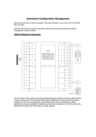
  • 1. Symmetrix Configuration Management With virtual LUN and an internal migration in the same storage, we can move from FC to SATA, SSD, etc disks. E20-335 certificacion de symm sol specialist. Faltaria el de symmetrix bussiness continuity management y puedo certificar. DMX Architecture Overview: The Symmetrix V-Max system uses Engine-based packaging containing Front End, Back End and memory components. The Symmetrix V-Max system implements a virtual matrix interconnect, enabled by a new version of Enginuity. As the table shows, the new architecture enables significant increases in scalability. Scalability has improved in all aspects: Front End connectivity, Global Memory, Back End connectivity and usable capacity.
  • 2. Let’s take a closer look at the Virtual Matrix Architecture. Symmetrix V-Max Series with Enginuity is built around a scalable Virtual Matrix interconnect design. The Virtual Matrix is redundant and dual active and supports all Global Memory references, all messaging, and all management operations including internal discovery and initialization, path management, load balancing, fail over, and fault isolation within the array. The Symmetrix V-Max array is comprised of 1 to 8 V-Max Engines. Each V-Max Engine contains two integrated directors. Each director has two connections to the V-Max Matrix Interface Board Enclosure (MIBE) via the System Interface Board (SIB) ports. Since every director has two separate physical paths to every other director via the Virtual Matrix, this is a highly available interconnect with no single point of failure. This design eliminates the need for separate interconnects for data, control, messaging, environmental and system test. A single highly-available interconnect suffices for all communications between the directors, which reduces complexity. The denomination SE (or Single Engine) is for a base VMAX that cannot be upgraded, opposed to the normal VMAX that no matter it is sold with a single engine, it can be upgraded and receive multiple engines later. Each director has two communications ports to the internal virtual matrix. Each director can communicate with the other directors, throught theseports. An i/o might be reeived by one engine, stored in the cache of another engine, and written to the drive by still another engine.
  • 3. In the following graphic, you can see the diretor, joined by the VMAX virtual matrix above, sharing its global cache memory.
  • 4.
  • 5. The key data processing components of a Symmetrix V-Max array are engines. A full-sized array can have up to eight engines. Each engine has two directors that service I/O requests from hosts and the disk drives. V-Max directors are similar to DMX directors, however they have twice as many ports. Each director has four independent slices. Each slice manages two to four external host ports or four internal drive ports. Each engine is a self-contained module with its own power supplies, batteries, environmental monitors, and internal and external I/O ports. Each director has connections to two independent virtual matrices. This lets the directors communicate and share in the I/O handling—an I/O processed by one director might be stored on drives managed by other directors. Each V-Max engine also has a global cache area. As you add engines, you increase the amount of cache in the array. It is considered to be global because any engine can access any other engine’s cache memory. All I/O into or out of the array is cached in memory. Each director has two communications ports to the internal virtual matrix. Each director can communicate with the other directors through these ports. An I/O might be received by one engine, stored in the cache of another engine, and written to the drive by still another engine. Host I/O operation are managed by the Enginuity operating environment, which runs in the Symmetrix I/O subsystem (channel directors and disk directors). Because each of the physical disks are indirectly seen as part of the I/O protocol, Symmetrix devices are presented to the host with the following configuration or emulation attributes: Maximum Volume size that can be configured on a V-Max is 262668 cylinders. If host applications require larger volumes, multiple volumes can be combined to form a metavolume. Each device has N cylinders. The number is configurable (blocks ÷ 960)
  • 6. Each cylinder has 15 tracks (heads) Each device track in a fixed block architecture (FBA) has 128 blocks of 512 bytes (64K) Note: prior to DMX3, the track size for FBA devices was 32K Mainframe hosts use Count Key Devices (CKD) uses variable block sizes.
  • 7. The Symmetrix is configured using a static configuration file called the IMPL.bin. The file is created initially using the SymmWin software from the Service Processor and loaded into each director in the Symmetrix. When modifying a configuration, the current IMPL.bin file is pulled from the Symmetrix and edited use Symmwin. SymmWin is an EMC written graphical-based application for managing a Symmetrix. Capabilities include: Building and modifying system configuration files (IMPL.bin) Issuing Inlines commands, diagnostic, and utility scripts Monitoring performance statistics Automatically performs periodic error polling for errors and events. Certain errors will cause the service processor to “Call Home”. SymmWin runs locally on a Symmetrix Service Processor or on a standalone PC. Running on the service processor allows communications with an operational Symmetrix. Running it on a standalone system allows you to build a new configuration or view and modify an archived configuration file. EMC’s Solution Enabler APIs are the storage management programming interfaces that provide an access mechanism for managing the Symmetrix. They can be used to develop storage management applications. SYMCLI resides on a host system to monitor and perform control operations on Symmetrix arrays. SYMCLI commands are invoked from the host operating system command line (shell). The SYMCLI commands are built on top of SYMAPI library functions, which use system calls that generate low-level I/O SCSI commands to the storage arrays. The SYMCLI configuration change command, symconfigure, is used to perform control operations on Symmetrix arrays and the array devices and ports. Some of the Symmetrix array controls
  • 8. include setting how many hypers per disk are allowed, and what type of devices the array will support, such as RAID 6 devices. Device controls include creating devices, mapping and masking devices, and configuring device pools. The symconfigure command is also used for reserving devices and releasing device reservations. To reduce the number of inquiries from the host to the storage arrays, configuration and status information is maintained in a Symmetrix host database file called the Symmetrix configuration database (default file name: symapi_db.bin). The SYMCLI Configuration Change Component, frequently referred to as the Config Manager is invoked using the symconfigure command. It can also be invoked through the Symmetrix Management Console GUI. Config Manager is capable of configuration operations in the Symmetrix. A few SRDF related configuration activities cannot be performed by Config Manager. These include: •Dynamic RDF group and pair creation and deletion which can be done with the symrdf command •Modification of dynamic RDF group parameters such as Prevent Automatic RDF Link Recovery which can be set using the symrdf command •Modify the RAs online upon Power On parameter which has to be set through the Symmetrix Service Processor using Symwin.
  • 9. The Config Manager architecture allows it to run Symwin scripts on the Symmetrix service processor. Configuration change requests are generated either by the symconfigure SYMCLI command or a SYMAPI library call generated by a user making a request through the Symmetrix Management Console (SMC) GUI. These requests are converted by SYMAPI on the host to Symmetrix syscalls and transmitted to the Symmetrix through the channel interconnect. The Symmetrix front end routes the requests to the service processor, which invokes Symmwin procedures to perform the requested changes to the Symmetrix. Since these scripts are the same ones that a Customer Services Engineer would employ to configure the Symmetrix, Config Manager is able to do almost everything that is possible through Symwin scripts. Note: The communication between storage devices has the purpose of replication and internal commands, hence is better to have a local symcli / solutions enabler client connected by gatekeepers to each storage instead of using it “remotely”, by the interstorage link. Operation Classes: Array Wide Operations Device Operations Metadevice Operations Device Mapping Device Pool Management RDF Configuration (Older Symmetrix Arrays) RDF Group parameters Front-end port attributes
  • 10. Configuration Manager operations can be divided into several classes. A detailed listing of the actions available under each class is described in the Symmetrix Array Controls Guide. Array wide operations allow the setting of Symmetrix metrics. Device operations comprise creation and deletion of devices, modification of device attributes and binding and unbinding of Thin devices to pools. Metadevice operations allow the formation and dissolution of metavolumes. Mapping makes a device available to a Symmetrix front-end port. Device pools operations allow for the management of Thin pools, Snap pools and SRDF DSE pools. RDF Configuration actions are more meaningful with the older Symmetrix arrays where static RDF groups are more prevalent. RA group parameters relate to RDF/A groups and DSE pools for SRDF/A. Front-end port attributes are set to cater to the needs of different vendors’ operating systems. Before making configuration changes, it is important to know the current Symmetrix configuration. Verify that the current Symmetrix configuration is a viable configuration for host-initiated configuration changes. The command: symconfigure verify -sid SymmID will return successfully if the Symmetrix is ready for configuration changes Free physical disk space can be checked using the command: symconfigure list -freespace [-units CYLINDERS|MB] -sid SymmID Use protected devices for storing data. Check the product documentation to understand the impact that a configuration change operation can have on host I/O. Configuration change requests are placed in a command file. The syntax for these commands is described in Chapter 1 of the Symmetrix Array Control CLI Product Guide. Prior to Enginuity 5669 only one class of commands could be submitted for execution at one time. Though that restriction does not exist today any more, changes to dynamic RDF, Save pools and protected expansion of striped metavolumes can still not be mixed with other class operations in the same command file.
  • 11.
  • 12. Before 5874 a configuration change request acquired Symmetrix lock 15 and prevented other changes from being made until the first was completed. In 5874 configuration changes need not be done one at a time. In 5874 a change operation only takes the resources it needs to do its job. The old locks 15 and 9 have been replaced with four separate locks described later. The new locks reserve system resources with greater granularity and for shorter duration on the Symmetrix V-Max. With Solutions Enabler 7.0 on a DMX running 5773 or earlier, locks will still be taken one at a time and no parallelism is allowed. Configuration Locks in 5874: This information shown here is not exposed to the user and hence not documented in the product guide. There are four kinds of locks that can be taken during a configuration change session. The granularity of the locks allow operations that do not take the same locks to run in parallel. Director locks are taken by changes when a director is affected. A mapping operation will lock the director to which a device is being mapped. However, a different device being mapped to a different director will not take the same locks and could therefore be mapped in parallel. The front end device lock is taken when the front end of the device, such as meta-formation or device mapping is being undertaken. The backend device lock is taken when the back end is being affected. An Optimizer swap affects the back end only. Changes that require a reloading of the IMPL.bin file take the static configuration lock.. This lock prevents other configuration changes that require IMPL changes. Other configuration changes can happen concurrently if they need device locks or director locks. There is a CE Config Lock, that is set from the Service Processor, that acts like the old lock 15. It prevents any other configuration changes from happening on the Symmetrix.
  • 13. In the example shown a group of devices being mapped to a director takes the front end lock for the devices involved and a lock on the director to which the devices are being mapped.
  • 14. A device creation operation takes the static configuration lock, the device front and back end locks for the devices being created. Since the devices being created are not the ones being mapped, the two changes can occur in parallel. If however, the device creation step also included a mapping step that mapped the newly created devices to the same director to which the first set of devices are being mapped, the two actions could not happen in parallel. On the right hand side are two hosts competing for the same front end director port. As a result one of the hosts that issues the second request for the front end director resources will fail to complete the change. Configuration change sessions can be viewed using the symconfigure query command. If there are multiple sessions running all session details are shown.
  • 15. In rare instances, it might become necessary to abort configuration changes. This can be done with the symconfigure abort command as long as the point of no return has not been reached. Aborting a change that involves RDF devices in a remote array might necessitate the termination of changes in a remote array. # symconfigure -sid 207 -session_id 39682 abort -noprompt A Configuration Change abort is in progress. Please wait... A Configuration Change operation is in progress. Please wait... Looking for an existing configuration session.............Established. The session changes are in the class of: Creating new symdevices { create dev count=1, size=2200 cyl, emulation=FBA, config=2-Way Mir,mvs_ssid=a; } The Application that initiated the configuration change : SYMCONFIGURE The Host that initiated the configuration change : api1051 The Process ID that initiated the configuration change : 12382 The session length : 18 secs Aborting configuration changes............................Aborted. Terminating the configuration change session..............Done. The configuration change session has been aborted. A Symmetrix can have over 64000 devices configured. Not all devices are accessed by every front-end port. Instead, specific devices are “mapped” to specific ports by assigning a channel address. Host systems discover and access Symmetrix devices using these Channel Addresses. For open systems hosts, the Channel address is the SCSI ID. Normally a host uses a combination of the Controller, Target, and Logical Unit Number to address a disk device. The Controller number is the Host Bus Adapter, the Target is the port on the Storage System and the Logical Unit Number is the Channel Address we assign.
  • 16. The reverse of mapping a device is unmapping a device. Unmapping can become necessary prior to a device being converted from one type to another e.g. a standard to a meta member. Before the device is unmapped it has to be set not ready. The unmap action will fail if the device is R/W enabled. Before connecting an open systems host to the Symmetrix the following questions should be answered: Which host is going to connect to which port. What are the operating systems and versions of the hosts. Number, type, and firmware levels for Host Bus Adapters (HBA). Is PowerPath or other multi-pathing failover software used. How many, what protection, what size volumes are required. Performance considerations (e.g. faster disks should be picked for high performance applications). On the host side, the host bus adapter (HBA) has to be configured with the correct drivers. Multi- pathing software if present needs to be set up on the host. The physical SAN connection between the host and the Symmetrix consists of cables and SAN equipment such as Fibre channel switches. Logical zones are needed to establish a connection between the host bus adapter and the Symmetrix front end ports. On the Symmetrix side the front end adapter (e.g. FA) needs to be cabled to the SAN and zoned such that the host HBA and the front end adapter (e.g. FA) are in the same zone. Zoning can be done using software from the SAN vendors. The characteristics of the front end adapter port, to which the HBA connects, need to be appropriately set so the host operating system can access the Symmetrix devices. Device
  • 17. mapping permits a device to be accessible through a front end port. Config Manager is the appropriate tool to perform both of these tasks.. Device masking permits only a subset of devices that are mapped to a port to be visible to an HBA. This feature allows multiple hosts to share the same Symmetrix front end port without encroaching on another host’s devices. Device masking is performed using the masking commands in Solutions Enabler symmask and symmaskdb. Storage Area Networks provide a fan-out capability where it is likely that more than one host is connected to the same Symmetrix port. The actual number of HBAs that can be configured to a single port is operating system and configuration dependent but fan-out ratios as high as 256:1 are currently supported. Reference the support matrix for specific configuration limitations. When several hosts connect to a single Symmetrix port, an access control conflict can occur because all hosts have the potential to discover and use the same storage devices. However, by creating entries in the Symmetrix’s device masking database (VCMDB), it is possible to control the volumes “seen” by a host. Device Masking is independent from zoning but zoning and masking are typically used together in an environment. Zoning provides access control at the port level. It establishes a logical connection between the host bus adapter and port on the storage system. Device masking allows a subset of volumes mapped to a port to be visible to the host bus adapter. With Fibre Channel, Device Masking uses the UWWN (Unique Worldwide Name) of Host Bus Adapters and a VCM database device. In iSCSI, the iSCSI Qualified Name (IQN) is used. Regardless of the protocol, the concepts are the same. The device-masking database (VCMDB) on each Symmetrix unit specifies the devices that a particular WWN or IQN can access through a specific Fibre port.
  • 18. The Volume Logix Database persistently maintains the device masking information. Originally the database was located directly on a Symmetrix Logical Volume. On DMX-3 it is maintained in the Symmetrix File System (SFS). Rather than create the actual VCMDB device, today we create a VCM Gatekeeper device which is used by the Solutions Enabler to access the database on the SFS, as the SFS volumes are not host addressable. The VCM Gatekeeper is a 6-cyl device. By default, the device masking VCMDB is accessible to all HBAs that log into the director port where the database is configured. Thus, any host with access privileges can effectively modify the contents of the database if it has device masking commands are installed. Beginning with Enginuity Version 5670, the VCMDB can be unmapped from any director that is not being used for masking control. This database, “VCMB” is now in a disk, with the SFS (symmetrix file system), the same as aclx/aclxdb. It is always recommended to run a symmaskdb –sid xx backup –f ‘backup.bkb’ before doing a config change and a symmask –sid xx refresh after it. Device Masking controls host access to a set of devices by maintaining a set of entries in the VCMDB on the array that defines the relationship between masked connections and devices. These entries are sometimes called initiator records. Each entry includes a host's HBA identity (WWN or iSCSI Qualified Name), its associated FA port, and a range of devices mapped to the FA port that should be visible only to the corresponding HBA. Once you make this VCMDB entry and activate the configuration, the Symmetrix makes visible to a host those devices that the VCMDB indicates are available to that host's initiator through that FA port.
  • 19. Volume Logix is the brand name for the software in the Symmetrix that performs the device masking function. The capability is built into Enginuity but its use is optional. An Initiator Group contains the world wide name or iSCSI name of a host initiator, also referred to as an HBA or host bus adapter. An initiator group may contain a combination of up to thirty- two, Fibre Channel initiators or eight, iSCSI names or a combination of both. There is a limit of eight thousand one hundred ninety-two, (8,192) initiator groups in a Symmetrix V-Max array.
  • 20. Port flags are set on an initiator group basis, with one set of port flags applying to all initiators in the group. However the FCID lockdown is set on a per initiator basis. An individual initiator can only belong to one Initiator Group. However once the initiator is in a group, the group can be a member in another initiator group. It can be grouped within a group. This feature is called cascaded initiator groups, and is only allowed to a cascaded level of one. A Port Group may contain any number of valid front end ports, FAs. Front end ports may belong to more than one port group. There is a limit of five hundred twelve (512) port groups. Before a port can be added to a port group the ACLX flag must enabled on the port. A Storage Group may contain up to four thousand ninety-six, (4,096) Symmetrix logical volumes. A logical volume may belong to more than one storage group. There is a limit of eight thousand one hundred ninety-two, (8,192) storage groups. Each Symmetrix logical volume is allowed up to 4 mirrors. Prior to Enginuity 5874, local mirrors and parity RAID mirrors would occupy a second mirror position. This limited the number of remote mirrors and TimeFinder/Mirror BCVs these volumes could be joined to. In 5874, TimeFinder/Mirror is no longer supported. Remote mirrors still occupy a mirror position but local mirrors no longer occupy a mirror position. Thus the 4 mirror limit is no longer a limiting factor. Apart from unprotected devices, which are not recommended, Symmetrix volumes can be configured with RAID-1, RAID-5 or RAID-6 protection.  BCVs are device types that are used for local replication.  RDF volumes are used for remote replication.  Virtual devices are used in TF/Snap. They are cache only devices and do not consume disk space.
  • 21.  Thin Devices are used for Virtual provisioning. They are cache only devices and do not consume disk space.  Diskless devices are used for cascaded R21s. They are cache only devices and do not consume disk space.  Save and Data devices hold the actual data for Virtual and Thin devices respectively.  Each of these devices can be created with the Configuration manager. Less commonly used devices, such as DRV devices have not been listed above.  VDEV + SAVE are used by TF/SNAP.  TDEV + DATA are used by Virtual provisioning.  Diskless device = R21, it is a position in memory used for cascaded SRDF.
  • 22. Once the four slots used as mirror positions, there cannot be another operation with the device (IE RAID1 uses 2 positions, TF mirror uses one, and SRDF uses another one) hence, no operations left to be done. If TF Clone is used, then 3 positions from the new device are free to use. An spare could not be involed in the four positions are used. VMAX uses only one position in RAID1, leaving one position free to use. (RVA as named before) In the command file, you can delete one or more Symmetrix devices from the specified Symmetrix array. Deleting a device frees the space that it once occupied for future use. There are restrictions on device deletions that are aimed at protecting the data on the devices or any devices that may have associations with that device. This is the reason behind not allowing the deletion of devices with Snap or BCV sessions. The complete syntax for device deletion is: delete dev SymDevName[:SymDevName];
  • 23. When devices are deleted, the device numbers they used to occupy disappear from the list of Symmetrix devices. Thus deletion of devices have the potential for creating noncontiguous device numbers in the Symmetrix.
  • 24. Although the configuration tool allows the deletion of existing devices, it does not allow the assignment of specific device numbers when new devices are being created. Symmwin uses internal algorithms for the best distribution and placement of devices in the Symmetrix and the user has no control over the placement or numbering of new devices. In the example shown, a gap was created in the Symmetrix device numbers after 1A4 due to the deletion of devices A5 and A6. However, a subsequent creation of 4 devices does not fill up the gaps left by the deletions. A meta device is a Symmetrix mechanism for defining a device larger than the current maximum hyper-volume size. You can concatenate existing devices to form a larger meta device that is presented to the host as a single addressable device. There are two kinds of meta devices - concatenated and striped: On a concatenated meta device addressing of data continues to the end of a device before any data on the next device is referenced. You can add or remove devs from a concatenated device, but EMC does not guarantees the data inside. On a striped meta device data on meta members is addressed in user-defined stripes or chunks instead of filling an entire volume first before addressing the next volume. The meta head is the Symmetrix device that is recognized by the host and used for performing I/O.
  • 25. It is not a good idea to stripe on top of a stripe. Thus, if host striping is planned and meta volumes are being used, concatenated meta volumes are better. Striped meta volumes perform better than concatenated meta volumes when there are enough spindles to support them. However, if the striping leads to the same physical spindle hosting two or more members of the meta volume, striping loses its effectiveness. In such a case, using concatenated meta volumes is better. In Virtual Provisioning environments it is advisable to use concatenated meta volumes in most cases. In rare cases for performance reasons striped meta volumes may be better.
  • 26. Before a meta can be formed, the devices must be unmapped to guard against data loss. Metavolumes can be formed from virtual and thin devices Members can be removed from the tail of concatenated metavolumes but not from striped metavolumes Metadevice creation: Metadevices can be created in either be formed using symconfigure or they can be automatically created using Solutions Enabler 6.5.1 or higher. The syntax for forming metavolumes is: form meta from dev SymDevName, config=MetaOption [, stripe_size=MetaStripeSize[cyl]] [, count=member_count]; The stripe size parameter is not used for Enginuity versions 5669 and later. It is always 1 cylinders or 1920 blocks.
  • 27. The explanation on auto-meta features is clearer in the man page for symconfigure than in the documentation. The first two settings are self explanatory. The auto_meta_member_size is the default member size when metavolumes are automatically created. The min_auto_meta_size specifies the size threshold that triggers auto meta creation. When users try to create a device greater than min_auto_meta_size, and auto_meta is enabled, a meta will be created. Possible values are between 0 and the maximum value from the table below (the default value is the same as the maximum value):
  • 28.
  • 29. Device Creation and Mapping: Before the newly created device can be used it has to be mapped to a front end port to which the receiving host is connected. For example, the output below indicates that the host DMX800SUN1 is connected to FA 2C port 0
  • 30. The unmapping step causes the device(s) to no longer be presented to the front end port. Hosts accessing the devices should cease I/O to the device(s) before unmapping. It is important to perform a bus scan after unmapping so the host is made aware of the missing device. Setting front end port flags allows the FA port to be compatible with different types of hosts and fibre topologies. The Common Serial Number, SCSI3 and SPC2 Protocol version are used across a variety of platforms. Volume set addressing is used by HP-UX hosts.
  • 31. Front end port flags can be overridden by the setting of HBA flags by using the symaccess command. To use auto provisioning groups on Symmetrix V-Max the ACLX flag must be enabled on the port
  • 32.
  • 33. SCM2-SUN1 / symconfigure -sid 57 -cmd reserve dev 00A5:00A8; -owner GB -comment Testing GB reserve -nop A Device Reservation update is in progress. Reserve_id = 000004 The Device Reservation update has succeeded. SCM2-SUN1 / symconfigure -reserved list -sid 57 Symmetrix ID: 000194900757 SYMMETRIX DEVICE RESERVATIONS Reserve Date Flags ID Reserved TM Owner Devices Port Addresses ------- ----------- ----- ------------- --------- --------------------------------- 000003 11/23 15:20 E- win3 00A1:00A2 - Comment: Testing Reservations 000004 11/23 15:25 E- GB 00A5:00A8 - Comment: Testing GB A Symmetrix device can have a number of attributes that are settable at device creation time. The attributes described here are documented in Chapter 1 of the Array Controls Guide. CKD_META volumes are the equivalent of striped meta volumes in the Mainframe world.
  • 34. Save devices provide the storage for TimeFinder Snap. When an application writes to a TF/Snap Virtual device, the data is stored on the save device. Save devices are also used as temporary storage to handle overflow data when an RDF/A delta set runs out of space in cache memory. Datadevs are the repository for data written to Thin devices. This two last type of devices cannot be rolledback. They must be deleted to resume its ‘save/data”-dev device attribute. SCSI_3 persistent reservation attribute, sometimes called the PER bit is used by a number of Unix cluster products such as Veritas and Sun. ACLX flag is set on a device, which acts as a gatekeeper to the auto provisioning information that resides on the Symmetrix file system. There is only one ACLX device per Symmetrix. In addition, ports have to have the ACLX flag enabled to participate in autoprovisioning. Dynamic RDF attributes allow a device to be configured as a dynamic R1 only (dyn_rdf1), dynamic R2 only (dyn_rdf2), or dynamic RDF1 or RDF2 device (dyn_rdf). Except under special circumstances, most devices are assigned the dyn_rdf flag. Device Attributes for Enginuity 5874 Dynamic RDF Groups (RA group or RDF group) Dynamic RDF groups allow creation and deletion of SRDF groups using the symrdf command Works over switched SRDF network. You can mix SRDF ports in the same group. If multiple ports, they are resilient or redundant. Sample command: symrdf addgrp –label label -sid xx -rdfg m -dir i -remote_sid yy -remote_rdfg n -remote_dir j Additional documentation is located in Chapters 3 and 7 of the SYMCLI SRDF manual. Dynamic RDF groups can be created between two Symmetrix arrays that are zoned together through a fiber or Gig-e switch. Creation and removal of the groups can be done quickly through the use of the symrdf command and do not require intervention from an EMC customer services engineer.
  • 35. Dynamic RDF Devices Use the symrdf command to permit quick creation and deletion of RDF pairs Devices can be: – R1 capable – R2 capable – R1 and R2 capable Dynamic RDF attribute of a device can be examined in the output of symdev show: # symdev show 95 -sid 35 Dynamic RDF Capability : RDF1_OR_RDF2_Capable Dynamic RDF devices can only exist in a Symmetrix that has the Dynamic RDF feature enabled. They can be created to be RDF1 capable, RDF2 capable, or RDF1 or RDF2 capable (as shown above). Dynamic RDF Pairs The Symmetrix must be set to allow Dynamic RDF Pairs Dynamic RDF Configuration State: Enabled A device file containing device pairs comprising source and target devices is needed Sample command: symrdf createpair –file device file -sid xx -rdfg n -type RDF1 -establish The file content is in stanza format, two columns, left column with source devices and right column with target devices. (i.e: DEV001 DEV009) RDF Group Attributes for SRDF/A
  • 36. The attributes assignable to RDF/A groups are shown here. Session priority is used when there are multiple RDF/A groups being used in a Symmetrix. In the event of cache shortage, the lower priority session (higher number) will drop before a higher priority session is dropped. The minimum cycle timer measures minimum the time that has to elapse before a cycle switch is undertaken. Transmit idle is a default setting of all RDF groups. When Transmit Idle is enabled on an RDF/A group, a temporary loss of network connectivity between source and target can be overcome by storing the writes in cache as long as there is cache available. If network connectivity returns before cache overflows, SRDF/A can continue cycle switching. If cache overflows before the network is restored, the session is dropped. The DSE (Delta Set Extension) related attributes refer to the devices that are used for storing overflow data from an SRDF/A cycle when the cache overflows. SRDF/A Session Characteristics: Session priority – Sessions can be assigned a value between 1 and 64 – If multiple SRDF/A sessions are contending for cache and there is no more cache available, the lower priority session drops first. Minimum Cycle Time – Minimum amount of time after which SRDF/A will attempt to switchcycles (aka delta sets) – Value of cycle timer can be set from 1 – 59 secs. All SRDF/A sessions are assigned a default priority of 33. If desired, a session can be assigned a priority between 1 and 64 where 1 is the highest priority and 64 the lowest. If Symmetrix cache fills up due to heavy SRDF/A traffic, the lowest priority session will be dropped first to free up cache resources. The minimum cycle time for SRDF/A is set to 30 seconds by default. Lowering the cycle time improves the RPO but it places a higher demand on the link bandwidth. Changing the cycle timer must therefore be done after careful consideration of host throughput and link bandwidth. There are three kinds of device pools supported by Enginuity: Snap pools and DSE pools contain save devices. These devices can be used in either kind of pool. Thin pools contain data devices, which cannot be used in Snap or RDF DSE pools. A Save device is assigned to a default pool after creation. These can be used by TimeFinder/Snap but not RDF/DSE.If both RDF and Snap pools are in use in the Symmetrix, it is a good practice to place devices into named pools that have been designated as Snap or DSE pools. Managing Device Pools Three kinds of pools – snap (contains save devices) – rdfa_dse (contains save devices) – thin (contains data devices – covered under Virtual Provisioning)
  • 37. When save devices are created, they are assigned to a default pool and are available for use by TimeFinder/Snap. When pools are created they have to be named and identified as TF/Snap or RDF/A DSE pools Save devices can be moved into named pools Maximum number of pools in a Symmetrix is 510 Since SRDF devices can belong to a variety of operating systems with different emulations, the DSE pools used with SRDF can contain any one of four kinds of devices. Each DSE pool can hold only one kind of device. SRDF/A DSE Pools Can be shared with multiple SRDF/A groups A single SRDF/A group can have at most one of each kind of pool associated with it. – FBA (Fiber Black Architecture) – CKD 3380 – CKD 3390 – AS400 A DSE pool can contain only one kind of the above four kinds of devices. TimeFinder/Snap Save Pools All save devices initially belong to a DEFAULT_POOL The DEFAULT_POOL is available for use by TimeFinder/Snap It is also possible to create named TimeFinder/Snap pools and move save devices into them To use a named snap pool the pool name can be specified when a TF/Snap session is created Pool space can be monitored using SYMCLI, SMC or Event daemon When a save device gets created, it is initially placed into a default pool. The devices in the default pool are available for use by TimeFinder/Snap but not RDF/DSE. If both Snap and RDF save pools are being used in a Symmetrix, it is best to create named pools that are explicitly designated for use by TimeFinder/Snap or RDF/DSE. TF Snap uses save devices in save pool, for destaging from cache, original position of snap. Snap should not be used when modifications are superior to 20%.
  • 38. With Enginuity 5874, users can create a group of host initiators called an initiator group; a group of director ports, or port group; and a group of Symmetrix devices, or storage group; then associate all three in a masking view. When the masking view is created, the devices are automatically mapped and masked and become accessible to the host(s). After the masking view is created, any objects (devices, ports, or initiators) added to an existing group automatically become part of the associated masking view. This means that no additional steps are necessary to add additional devices, ports, or initiators to an existing configuration. All necessary operations to make them part of the configuration are handled automatically by Enginuity once the objects are added to the applicable group. This reduces the number of commands needed for mapping and masking devices and allows for easier storage allocation and de-allocation. Prior to creating groups, organization of host applications, corresponding storage tiers and naming conventions should be performed to ensure a logical layout of the storage environment. One of SLS Banks challenges is the dynamic multi-platform environment particularly the increased adoption of virtual machines. The storage administrator has to maintain SLAs for various storage configuration changes and is concerned about the impact of the increasing complexity of these changes. Autoprovisioning can be implemented to dramatically reduce the time and complexity associated with these changes.
  • 39. SYMCLI Filtering facilitates Device Search Options in “symdev list” and SMC facilitate filtering – N : Sets the number of devices to list. The # specifies the maximum number of devices to return. The actual number returned may be less than the specified number if fewer devices exist. The default is to list all devices. – RAID1, RAID5 [-protection 3+1 | 7+1], RAID6 [-protection 6+2 | 14+2] Lists RAID-1, RAID-5 and RAID-6 devices – CAP : Sets the device capacity to a specific value (in megabytes) for the selection criteria to be listed. To find 5 unmapped standard 8.6 GB RAID5 (7+1) devices in disk group 1 symdev list –sid 1201 –raid5 –protection 7+1 –noport –N 5 –nobcv -disk_group 1 –cap 8631 Utilizing device filtering flags will help to expedite the storage selection process by allowing you to define, in advance, the characteristics of the devices you want to display in the output of “symdev list” statements. Filtering mechanisms can work well within scripts. For example: Perform above search and add found devices into an existing device group called “appgrp2”. for dev in $(symdev list –sid 1201 –raid5 –protection 7+1 –noport –N 5 –nobcv -disk_group 1 –cap 8631 | grep ???:? | awk '{print $1}'); do symld -g appgrp2 add dev $dev -sid 1201; done Rationale for Autoprovisioning Newer larger arrays contain greater numbers of devices Makes it easier to provision storage in environments with clusters and hosts using multiple paths to the array Performed through use of the symaccess command Command symsg added in Solutions Enabler 7.1 to manage Storage Groups: – Used for Autoprovisioning and for FAST Storage Tiering – Performs many of the functions that symaccess performs – Similar in command structure to symdg and symcg As the number of volumes in a single array continues to climb higher, a more flexible scheme for provisioning storage needed to be developed. Autoprovisioning makes it easier to provision storage in large enterprises. Autoprovisioning in the Symmetrix V-Max is achieved through the use of the symaccess command. The symsg command was introduced in Solutions Enabler V 7.1 for use with FAST (Fully Automated Storage Tiering) and with Autoprovisioning. The syntax for symsg is compatible with that of symdg and symcg. Autoprovisioning requires the use of Initiator Groups, Port Groups and Storage Groups. Initiator groups contains host initiator or iSCSI names. Port Groups contain valid front end FA or Gig-E ports. Storage groups contain Symmetrix devices. One of each type of group is bound together to form a Masking View.
  • 40. Steps for provisioning storage In a simple configuration it is possible to create a masking view for a single initiator on a single port with any number of devices using just one symaccess command. The following are the general steps that can be followed to accomplish this goal: 1. Create a view and specify a view name, HBA WWN, front-end port, and Symmetrix volumes for the first path. 2. Create a view and specify a view name, HBA WWN, front-end port, and Symmetrix volumes for the second path. Once the masking view has been created, the devices are available to the
  • 41. initiators on the storage ports. Host-specific commands can then be run to configure the devices to the operating system. Example of provisioning storage: Step 1 - Create a view and specify a view name, HBA WWN, front-end port, and Symmetrix volumes for the first path. When using this method, the view is given a name by the user and that name is used for the initiator, port, and storage groups. The symaccess list hba command can be used to print the HBA WWNs and the ports that they are zoned to: # symaccess list hba Identifier Physical Device Path Symmetrix ID Dir:P ---------------- -------------------------------- ------------ ----- 10000000c9767816 c3t5000097208139918d0s2 000192601254 07E:0 10000000c9767817 c4t5000097208139959d0s2 000192601254 07F:1 Gatekeepers 08F – 092 will be made available on the first path: # symaccess create view -name mgmtGKpath0 -wwn 10000000c9767816 -dirport 7E:0 devs 08F:092 -sid 54 Step 2 - Create a view and specify a view name, HBA WWN, front-end port, and Symmetrix volumes for the second path. Gatekeepers 093 – 096 will be made available on the second path: # symaccess create view -name mgmtGKpath1 -wwn 10000000c9767817 -dirport 7F:1 devs 093:096 -sid 54 The devices are now available to the initiators on the storage ports. After the host configures the devices, they are available to the operating system on both paths: # symaccess list view -sid 54 Symmetrix ID : 000192601254 Masking View Name Initiator Group Port Group Storage Group ------------------- ------------------- ------------------- ----------------- mgmtGKpath0 mgmtGKpath0 mgmtGKpath0 mgmtGKpath0 mgmtGKpath1 mgmtGKpath1 mgmtGKpath1 mgmtGKpath1 # syminq Device Product Device ---------------------------- -------------------------- --------------------- Name Type Vendor ID Rev Ser Num Cap (KB) ---------------------------- -------------------------- --------------------- /dev/rdsk/c3t50*8d0s2 GK EMC SYMMETRIX 5874 5400054000 5760 /dev/rdsk/c3t50*8d1s2 GK EMC SYMMETRIX 5874 540008F000 5760 /dev/rdsk/c3t50*8d2s2 GK EMC SYMMETRIX 5874 5400090000 5760 /dev/rdsk/c3t50*8d3s2 GK EMC SYMMETRIX 5874 5400091000 5760 /dev/rdsk/c3t50*8d4s2 GK EMC SYMMETRIX 5874 5400092000 5760 /dev/rdsk/c4t50*9d0s2 GK EMC SYMMETRIX 5874 5400054000 5760 /dev/rdsk/c4t50*9d1s2 GK EMC SYMMETRIX 5874 5400093000 5760 /dev/rdsk/c4t50*9d2s2 GK EMC SYMMETRIX 5874 5400094000 5760 /dev/rdsk/c4t50*9d3s2 GK EMC SYMMETRIX 5874 5400095000 5760 /dev/rdsk/c4t50*9d4s2 GK EMC SYMMETRIX 5874 5400096000 5760 # symcfg discover This operation may take up to a few minutes. Please be patient...
  • 42. # symaccess show view mgmtGKpath0 -sid 54 Symmetrix ID : 000192601254 Masking View Name : mgmtGKpath0 Initiator Group Name : mgmtGKpath0 Host Initiators { WWN : 10000000c9767816 } Port Group Name : mgmtGKpath0 Director Identification { FA-7E:0 } Storage Group Name : mgmtGKpath0 Sym Dev Host Name Dir:P Physical Device Name Lun Attr Cap(MB) ------ ----- ----------------------- ---- ---- ------- 008F 07E:0 c3t5000097208139918d1s* 1 5 0090 07E:0 c3t5000097208139918d2s* 2 5 0091 07E:0 c3t5000097208139918d3s* 3 5 0092 07E:0 c3t5000097208139918d4s* 4 5 # symaccess show view mgmtGKpath1 -sid 54 Symmetrix ID : 000192601254 Masking View Name : mgmtGKpath1 Initiator Group Name : mgmtGKpath1 Host Initiators { WWN : 10000000c9767817 } Port Group Name : mgmtGKpath1 Director Identification { FA-7F:1 } Storage Group Name : mgmtGKpath1 Sym Dev Host Name Dir:P Physical Device Name Lun Attr Cap(MB) ------ ----- ----------------------- ---- ---- ------- 0093 07F:1 c4t5000097208139959d1s* 1 5 0094 07F:1 c4t5000097208139959d2s* 2 5 0095 07F:1 c4t5000097208139959d3s* 3 5 0096 07F:1 c4t5000097208139959d4s* 4 5 Additional elements such as initiators, ports, or volumes can be added, as needed, to the groups that are created by the command. Note: Running symcfg discover is not required; however, the Physical Device Name field in symaccess show view will display the devices as “Not Visible” until they are configured by the host and symcfg discover is run.
  • 43. Symaccess Control Operations symaccess is a function rich command and has a number of control actions and a couple of display actions. A summary of the control actions is provided here. Symaccess Display Commands Symsg Control Operations
  • 44. The syntax for symsg is similar to that of other group commands such as symdg and symcg. It has a number of control actions and a couple of display actions. A summary of the control actions is provided here. Storage Groups Contain Symmetrix Devices Device reservations are enforced when adding devices to a storage group Device can belong to more than one storage group Storage group names can be up to 64 characters, and are not case sensitive. Group names must be unique per group type, but different group types can share the same name. For example, a storage group, a port group, and an initiator group can all have the name Financial_DB. However, two storage groups cannot be named Financial_DB. Device reservations will be enforced whenever devices are being added to a storage group. Storage Group Command Syntax #symaccess create –sid 458 –name SG_1 –type storage devs 50:52 OR #symsg create –sid 458 SG_1 #symsg –sg SG_1 addall devs –range 50:52 You can create a storage group using a range of devices, device names, device group devices, or a device file. The example shows how to use both symaccess and symsg commands to create storage groups. Common Operations on Storage Groups
  • 45. Port Groups : Contain valid front end ports A port can belong to more than one port group Only Fibre and Gig-E ports on front end directors allowed Ports must have ACLX flag enabled Port groups may contain any number of valid front-end ports. A port can belong to more than one port group. Only Fibre and Gig-E ports on front-end directors will be allowed to be added to a port group. Port groups can have mixed port types. Ports must have the ACLX flag enabled to be added to a port group. Port Group Creation Command Syntax symaccess create -sid 80 -name PG_1 -type port –dirport 7E:0,7G:1,8F:0 Port groups may contain any number of valid front-end ports. A port can belong to more than one port group. Only Fibre and Gig-E ports on front-end directors will be allowed to be added to a port group. Port groups can have mixed port types. Ports must have the ACLX flag enabled to be added to a port group. The syntax for port group creation is: symaccess –sid SymmID create -name GroupName -type port [-dirport Dir:Port [,Dir:Port...]] Common Operations on Port Groups Initiator Group: An initiator group is a container of one or more host initiators (Fibre or iSCSI). Each initiator group can contain up to 32 entries. An initiator group may also include the name of another initiator group to allow the groups to be cascaded to a depth of one.
  • 46. NOTE: An HBA may only belong to one group, but may have masking views for both an upper and lower group if cascaded. Contains Fibre WWNs or iSCSI names Maximum of 32 entries An initiator may belong to only one IG IGs can be cascaded one deep, an IG can belong to one or more IGs Example: – Initiator Group IG_1 contains WWN1 – Initiator Group IG_2 contains WWN2 – Initiator Group IG_Both can contain IG_1 and IG_2 Initiator Group Creation Syntax #symaccess create -sid 80 -name hp1_Initiators -type initiator #symaccess -sid 80 -name hp1_Initiators -type initiator -wwn 50060b00000788a8 add #symaccess -sid 80 -name hp1_Initiators -type initiator -wwn 50060b0000077fbc add OR #symaccess create –sid 80 –name hp1_Initiators –type initiator –file HBA_WWNS File HBA_WWNS contains wwn:50060b00000788a8 wwn:50060b0000077fbc You can create an initiator group using the HBA’s WWN, iSCSI, a file containing WWNs or iSCSI names, or another initiator group name. The symaccess syntax for creating an initiator group is: symaccess -sid SymmID create -name GroupName -type initiator [ -wwn wwn | -iscsi iscsi | -file InitiatorFilename | -ig InitiatorGroupName ] [-consistent_lun] Common Operations on Initiator Groups
  • 47. Use the -consistent_lun option if the devices of a storage group (in a view) need to be seen on the same LUN on all ports of the port group). If the -consistent_lun option is set on the initiator group, Solutions Enabler will make sure that the LUN number assigned to devices is the same for the ports. If this is not set, then the first availale LUN on each individual port will be chosen. Masking View Command Syntax #symaccess create view –sid 458 –name MV_1 –sg SG_1 –pg PG_1 -ig IG_1 Storage Group contains Symmetrix Devices. A Masking View Contains: 1 Initiator Group + 1 Port Group + 1 Storage Group. On a Symmetrix V-Max Autoprovisioning groups allow storage administrators to create groups of hos initiators, front-end ports, and logical devices. These groups are then associated to form a masking view, from which all controls are managed. A masking view is a container of a storage group, a port group, and an initiator group. When you create a masking view, the devices in the storage group become visible to the host. The devices are masked and mapped automatically. Dynamic LUN addressing is enabled by default. SYMAPI checks the SFS and assigns the next available LUN address when the masking view is created. The syntax is: symaccess –sid SymmID create view -name ViewName -sg StorageGroupName -pg PortGroupName -ig InitiatorGroupName [ [-reserve_id ResvID[,ResvID[,ResvID...]]] [-lun Addr]
  • 48. Common Operations on Masking Views Reason for Dynamic LUN Addressing Inside the Symmetrix each FA assigns a device a LUN value after mapping # symcfg list -sid 80 -avail -addr -fa 7F -p 0 ………………………………………………………………………………………………………………………………………… Director Device Name Attr Address ---------------------- ----------------------------- ---- -------------- Ident Symbolic Port Sym Physical VBUS TID LUN ------ -------- ---- ---- ----------------------- ---- --- --- FA-7F 07F 0 0028 c2t50000972C002D158d0s* ACLX 0 00 000 00B1 /dev/rdsk/emcpower50c 0 00 001 00B2 /dev/rdsk/emcpower54c 0 00 002 00B3 /dev/rdsk/emcpower58c 0 00 003 ………………………………………………………………………………………………………………………………………… 0194 Not Visible 0 00 044 - AVAILABLE 0 00 045 * Sometimes the LUN values assigned by the FA are unsuitable for the host – FA assigned values can exceed the HBA’s ability to address – Applications may require a specific LUN number to function correctly A Symmetrix FA port is capable of supporting 4096 mapped devices. It assigns LUN numbers to mapped devices starting at 0 and counting up in 3 hexadecimal digits. For some host environments this is a problem, because some host HBAs are limited in the highest LUN that they can support. In other instances, applications might rely on a certain LUN such as LUN 0. Dynamic LUN addressing addresses this problem. Dynamic LUN Addressing with Autoprovisioning Dynamic LUN addressing allows specific LUN values to be assigned, either manually or automatically, to each Symmetrix device that is being masked to an HBA, regardless of what LUN was assigned when the device was mapped to the FA. This eliminates the potential impact of the 256 LUNs per target limit of many HBAs by allowing LUN addresses between 0 and 255 to be
  • 49. specified on a per HBA World Wide Name basis. It also allows any device to be addressed as LUN 0 if a host requires that a device be assigned that LUN value. Dynamic LUN Addressing is enabled by default. By default Symmetrix array assigns the next available LUN address on the FA port when the masking view is created. If needed user can define LUN address making LUN addresses consistent across FAs Example: Create a masking view named Prod1_View utilizing pre-existing group components Prod1_IG, Prod1_PG, and Prod1_SG. Optional - use a starting LUN address of 040 for devices symaccess –sid 1201 create view –name Prod1_View –sg Prod1_SG –pg Prod1_PG –ig Prod1_IG –lun 040 Examples of List Output DMX800SUN1/usr/sengupta symaccess list view -sid 80 Symmetrix ID : 000194900180 Masking View Name Initiator Group Port Group Storage Group ------------------- ------------------- ------------------- ------------------- WIN1_MaskingView WIN1_Initiators WIN1_Ports WIN1_StorageGroup sun1_MaskingView sun1_Initiators sun1_Ports sun1_StorageGroup ibm1_MaskingView ibm1_Initiators ibm1_Ports ibm1_StorageGroup lin1_MaskingView lin1_Initiators lin1_Ports lin1_StorageGroup hp1_MaskingView hp1_Initiators hp1_Ports hp1_StorageGroup DMX800SUN1/usr/sengupta symaccess list -type port -sid 80 -detail Symmetrix ID : 000194900180 Port View Port Group Name Count Count -------------------------------- ----- ----- WIN1_Ports 2 1 hp1_Ports 2 1 ibm1_Ports 2 1 lin1_Ports 2 1 sun1_Ports 2 1 Examples of Show Output DMX800SUN1/usr/sengupta symaccess show hp1_StorageGroup -type storage -sid 80 Symmetrix ID : 000194900180 Last updated at : 04:07:26 PM on Tue May 19,2009 Storage Group Name : hp1_StorageGroup Devices : 0029:005D 005F 0061 0063 0065:006C Masking View Names { hp1_MaskingView } DMX800SUN1/usr/sengupta symaccess show lin1_Initiators -type initiator -sid 80 Symmetrix ID : 000194900180 Last updated at : 04:07:21 PM on Tue May 19,2009 Initiator Group Name : lin1_Initiators Host Initiators { WWN :10000000c94eadda WWN :10000000c94eaddb } Masking View Names { lin1_MaskingView } Parent Initiator Groups { None}
  • 50. Setting HBA Flags The following HBA flags can be set on a per initiator or initiator group basis – Common_Serial_Number [C] – Disable_Q_Reset_on_UA [D] – Environ_Set [E] – Volume_Set_Addressing [V] – Avoid_Reset_Broadcast [ARB] – AS400 [AS4] – OpenVMS [OVMS] – SCSI_3 [SC3] – SPC2_Protocol_Version [SPC2] – SCSI_Support1 [OS2007] Symmetrix V-Max arrays allow you to set the HBA port flags on a per initiator or initiator group basis. This feature allows specific host flags to be enabled and disabled on the director port. To set (or reset) the port flags, use the following form: symaccess -sid SymmID -wwn wwn | -iscsi iscsi set hba_flags on flag,flag,flag... -enable |-disable |off [flag,flag,flag...] list logins [-dirport Dir:Port] [-v] symaccess -sid SymmID -name GroupName -type initiatorset ig_flags on flag - enable |-disable | off [flag] A flag cannot be set for the group if it conflicts with any initiator in the group. After a flag is set for a group, it cannot be changed on an initiator basis. Mapping and Unmapping with symaccess Mapping – if symaccess finds unmapped devices during view creation, it will map the unmapped devices to all ports in the port group associated with the view – In prior versions of Solutions Enabler, mapping of devices usingsymconfigure was an essential step before masking Unmapping – The user has the option of Unmapping all devices when the view is deleted Unmapping devices that are removed from a storage group while that storage group is part of a view Unmapping devices from the port if that port is removed from a port group (the port group has to be part of a view for this to happen) – All affected devices including those mapped with symconfigure will be unmapped. The symaccess command will map devices to a port if needed at the time of view creation. The mapping happens automatically without user intervention. However, it takes longer to create a masking view, if the devices have to be mapped as well.
  • 51. Unmapping of devices can be performed when a view is deleted symaccess –sid 80 delete view –name MV –unmap Unmapping of devices that are part of a storage group which is participating in a masking view symaccess –sid 80 –name SV –type storage remove dev 011 –unmap Unmapping of devices from a port that is participating in a masking view when the port is removed from the masking view symaccess –sid 80 –name PV –type port –dirport 7E:0 –unmap remove This is a practical example of how one might configure shared storage intended for a cluster or a shared database. In a clustered environment, some devices need to be seen by the all the hosts in the cluster. Other devices such as gatekeepers may need to be seen only by individual hosts in the cluster. To achieve this, FOUR initiator groups, FOUR storage groups, and FOUR masking views are created. We’ll assume one port in one port group to keep the example simple. The storage groups are straightforward. Each of the four pools of storage are placed in a storage group. The first three initiator groups contain one WWN each. The fourth initiator group is a cascaded initiator group which contains the names of the three initiator groups, which contain the HBA WWNs. Using the cascaded initiator group it is possible to give all the initiator groups access to the shared storage while each individual initiator retains private access to its gatekeepers. Using the 4 storage groups and 4 initiator groups it is now possible to construct 4 masking views
  • 52. Steps to Replace an HBA: The replace action can be used to allow a new HBA to take over the devices visible to the old HBA View old HBA WWN symaccess list logins Swap out the old HBA board with the new HBA Discover the WWN of the new HBA symaccess discover hba or symaccess list hba Use the replace action symaccess –sid 80 replace –wwn WWN_old -new_wwn WWN_new Use the rename action to establish the new alias for the HBA symaccess discover hba -rename In the event a host adapter fails, or needs replacement for any reason, you can replace the adapter and assign its set of devices to a new adapter by using the replace action in the following form: symaccess replace -wwn wwn -new_wwn NewWWN [-noprompt] Thin pools now can be shrunk non-disruptively, helping reuse space to improve efficiency. When a data device is disabled, it will first move data elsewhere in the pool by draining any active extents to other, enabled data devices in the thin storage pool. Once the draining is complete, that device (volume) is disabled and can then be removed from the pool.
  • 53. Reasons for for V-LUN Migration Migration of applications between tiers of storage Migration of applications from one class of RAID protection to another Information Lifecycle Management Performance Optimization Virtual LUN Migration allows Symmetrix users to seamlessly move application data between different storage tiers. If data for an application is initially placed on a lower tier of storage and performance needs increase, V-LUN Migration allows the application to be moved to faster disks without interruption of production. V-LUN migration permits applications to move from one class of RAID protection to another to save storage space, e.g. RAID-1 to RAID-5. As data ages and the need for its availability diminishes, it can be moved to less expensive storage as part of the ILM process. Performance optimization is another function of V-LUN migration as applications are moved between storage tiers Enhanced Virtual LUN Technology Non-disruptive migration of devices and meta devices – Between RAID levels or Disk Groups – Key enabler for storage tiering within the array Symmetrix V-Max with Enginuity 5874 enables users to perform non-disruptive migration of volumes among storage tiers within the same array and between RAID protection schemes. Enhanced Virtual LUN technology is supported for both open systems (FBA) and mainframe volumes (CKD), and includes support for meta volumes. Virtual LUN Technology is a licensed feature bundled under the Symmetrix Optimization offering which includes Symmetrix Optimizer. However, DRV volumes are not needed for Enhanced Virtual LUN Technology.
  • 54. Virtual LUN technology enables data migration within an array without host or application disruption allowing an Information Lifecycle Management (ILM) strategy to be adapted over time by easily moving information throughout the storage system as requirements change. It can assist in system reconfiguration, performance improvement, and consolidation efforts all while helping maintain vital service levels. In this example, data may start out on a set of tier 0 volumes such as Enterprise Flash Drives. Over time, that data may no longer warrant the high performance of Flash Drives. Migrating that data off array is time consuming and disruptive. However, leveraging Virtual LUN technology, this data can be moved to another tier in the same array without needing to shut down applications or systems and without disrupting local or remote replication. RAID Virtual Architecture RAID Architecture with Enginuity 5874 – Abstracts RAID protection from Device – RAID Group occupies single mirror position – Enabling technology for Virtual LUN migration and Fully Automated Storage Tiering (FAST) – All RAID types (RAID-1, RAID-5, RAID- 6) supported. RAID Virtual Architecture implemented with Enginuity Operating Environment 5874 is used for handling device mirror position usage. RAID Virtual Architecture is an enabling technology for the Enhanced Virtual LUN technology and Fully Automated Storage Tiering (FAST). Note that RAID Virtual Architecture does not introduce any new RAID types. All device protection types use the same I/O execution engine which separates the mirror position interface from RAID internal operations. With the RAID virtual architecture a mirror position holds a logical representation of a RAID group rather than a device, resulting in additional free mirror positions as demonstrated in this example. Notice the RAID 5 volume with SRDF protection consumes only two mirror positions. The RAID 5 group occupies only one mirror position with the SRDF protection occupying a second position. This frees two mirror positions for other operations such as a migration to another RAID type. RVA Operations and Limitations 2 RAID Groups Attached – During migration only – RAID Groups can be in different Disk Groups – Non-disruptive to local and remote replication The diagram shows the migration process of an R2 device, which has one remote mirror. When a migration is initiated, the target device occupies the third mirror position during the course of the migration. The RAID Virtual Architecture (RVA) will allow a maximum of two RAID groups attached as a mirror at the same time. However, this is a transitional state to support operations such as
  • 55. migrations and Optimizer swaps. The array operations associated with the RAID groups will be handled independently for both attached groups. The attached RAID groups may be in different disk groups containing different capacities and speeds. Symmigrate symmigrate–f dev_pairs.txt establish symmigrate –name mig_01 Solutions Enabler 7.0 introduced the SYMCLI command, symmigrate, which can be used to perform and monitor migrations. When performing a migration you must designate the source which is the device the data will be migrated from. The device can be selected from the Symmetrix Management Console or on the command line by device group, an auto provisioning storage group, or by a device file that contains a single column listing only the desired source devices. Next you will need to identify the target which is the volume the data will be migrated to. The criteria and syntax for designating the target will vary based on whether the target is unconfigured or configured. A symcli device group cannot be designated as a target. When working with configured space you can control which source volumes are migrated to which target volumes by creating a device file with two columns. The first column containing the source device numbers and the second column containing the desired target device numbers. Migrations are submitted and managed as sessions, so you can use a session name using the – name option. Note that the control host for the migration must be locally connected to the Symmetrix V-Max array on which the migration is being performed. Symmigrate Operations
  • 56. The symmigrate command has three control actions and three monitor actions. The control actions include validate which tests the user input to see if it will run, establish which creates the migration session and start the synchronization process, and terminate which removes a session by name. The terminate action can only be performed when all volumes in the session are in the Migrated state. The monitor actions include query which provides status about a specified session, list which shows all sessions for a given Symmetrix array or all local Symmetrix arrays, and verify which determines if the specified session is in a specified state. Implementation Migration facilitated by the creation and movement of RAID groups Target RAID group added as secondary mirror Target RAID group then made primary mirror Upon completion of the migration the original RAID group is either deleted or an iVTOC is performed. V-LUN migration is made possible by the creation and movement of RAID groups. Initially the target RAID group is added as a secondary mirror. Once the migration completes, the target RAID group is made the primary mirror. If migrating to unconfigured space, the target RAID group, i.e. the original source device is deleted. If migrating to configured space the target device, i.e. the original source device is iVTOC’d after the migration is completed. V-LUN Migration can be controlled either from the command line using the symmigrate command or from the SMC GUI.
  • 57. Virtual LUN Migration To Configured Space – 1 In the first example we will demonstrate a Virtual LUN Migration which transfers two volumes non-disruptively from RAID-1 to RAID-6 protection. The symmigrate validate command checks the Symmetrix for suitable migration candidates. In our example the validation step identifies devices 191 and 192 as suitable targets for migration. The RAID-1 volumes are part of disk group 1 and the RAID-6 volumes are in disk group 2. When the LUN migration starts the RAID-6 volume temporarily takes up a mirror position while the two volumes are synchronized. Once the migration is complete the original target device assumes the identity of the source and the original source assumes the identity of the target. Data on the target LUN, i.e. the original source is destroyed through IVTOC. Virtual LUN Migration To Configured Space – 2 We’ll start with a device group called Appdg. It contains two devices 1078 MB in size. Note that the back end of these devices are connected to directors 7B:D0 and 7D:D0. A look at the symdisk output shown on the slide and in the notes section tells us that both of the devices are in disk group 1. DMX800SUN3/ symdisk list -da 7D -interface D -tid 0 -v Symmetrix ID : 000194900182 Disks Selected :1 Director : DF-7D Interface :D Target ID :0 Disk Group Number :1 ………………………………………………………………………………………………………………………………………… In real life environments, a disk group usually comprises disks of the same type of size and performance. Devices with different performance characteristics are placed in different disk groups. Symmetrix devices do not cross disk groups, because that would interfere with tiering storage. Here, we can conclude that both devices reside on disk group 1.
  • 58. Virtual LUN Migration To Configured Space – 3 DMX800SUN3/ symmigrate validate -nop -outfile devlist -g Appdg -tgt_raid6 -tgt_prot 6+2 - tgt_dsk_grp 2 -tgt_config -name migdemo1 'Validate' operation execution is in progress for the device group 'Appdg'. Please wait... Validate Migration..............................................Started. Validate Migration..............................................Done. 'Validate' operation successfully executed for the device group 'Appdg'. DMX800SUN3/ cat devlist b2 0192 b1 0191 The validate command queries the Symmetrix to find if there are devices that suit the criteria that we asked for, namely, RAID-6 devices with 6+2 protection. The –tgt_config option specifies that the migration should be undertaken to configured space. If valid targets exist the device pairing should be written out to a file. This file can later be used as input to the symmigrate command. Virtual LUN Migration To Configured Space – 4 Here we take a look at the two devices suggested by the output of the validate command. A little known fact is that interrogation marks in the SA column in the symdev list output mean the devices are unmapped. Asterisks mean that the devices are mapped to more than one front end port. There happen to be two RAID-6 devices in this Symmetrix that are not mapped to any director as evidenced by the interrogation marks in the SA column. The devices in the output are connected to backend directors 7A:C4 and 7D:D4. The devices are in disk group 2. They are suitable targets for our migration.
  • 59. Virtual LUN Migration To Configured Space – 5 Virtual LUN Migration To Configured Space – 6
  • 60. The query output shows slightly different information. We see here that the migration is complete. A listing of the device group shows that devices B1 and B2 are now RAID-6 protected and the back end directors are 7A:4 and 7D:4 Virtual LUN Migration To Configured Space – 7 The old devices 191 and 192 have now become RAID-1 devices connected to backend directors 7B:D0 and 7D:D0. The data on the old physical devices, which are now 191 and 192 is no longer available as the logical volumes have gone through a VTOC. Finally, the session can be terminated. Migration To Configured Space: Summary After specifying configured space and the target protection (or disk type), the establish action instructs the array to perform the following steps: 1. An available target Symmetrix LUN is determined with a RAID group of the protection and disk type specified. 2. The RAID group is disassociated from the target Symmetrix LUN and is associated to the Symmetrix LUN being migrated as the secondary mirror. 3. The secondary mirror is synchronized to the primary mirror. 4. The primary and secondary indicators are swapped between the two mirrors. 5. The secondary mirror, which is now pointing to the original RAID group, is disassociated from the Symmetrix LUN being migrated and associated as the primary mirror to the target Symmetrix LUN. 6. The target Symmetrix LUN is then iVTOC’d to clear the data from it.
  • 61. Virtual LUN Migration To Unconfigured Space – 1 This time we’ll perform a migration from the same device group to unconfigured space. The unconfigured space to which the data is being moved is designated on the command line with the option –tgt_unconfigured. When migrating to unconfigured space we must designate the desired target configuration and protection on the command line, in this case we are designating RAID 1 which will be built automatically and placed in the next available mirror position. Once we issue the command, the migration session is established and the source is synchronized with the target, while also servicing production I/O from the host. After synchronization completes, the target assumes the identity of the source. The source is then deallocated and the storage capacity is freed up in the original disk group. From the host’s point-of-view this operation is completely transparent. Keep in mind that migrating to unconfigured space is a slightly longer operation as the target configuration is created before the migration begins. Virtual LUN Migration Using Unconfigured Space Use Case: Migration of production volumes across RAID tiers
  • 62. Virtual LUN Migration To Unconfigured Space – 2 This time we will move devices B1 and B2 from the device group Appdg back to disk group 1 with RAID-1 protection. We first validate if this will work and execute the migration. The session takes a little longer to create because the Symmetrix has to search for suitable space. Virtual LUN Migration To Unconfigured Space – 3
  • 63. As can be seen devices B1 and B2 are back to being 2-Way-Mir or RAID-1 protected devices Virtual LUN Migration To Unconfigured Space – 4 B1 and B2 are again part of disk group 1. Migration To Unconfigured Space: Summary
  • 64. After specifying unconfigured space and the target protection (or disk type), the establish action instructs the array to perform the following steps: 1. A new RAID group of the specified protection type is created on the specified disk type. 2. The newly created RAID group is associated to the Symmetrix LUN being migrated as the secondary mirror. 3. The secondary mirror is synchronized to the primary mirror. 4. The primary and secondary indicators are swapped. 5. The secondary mirror, which is now pointing to the original RAID group, is deleted. Supported and Unsupported Features Interoperability considerations for the Virtual LUN migration feature are shown here. First, Virtual LUN migration requires that either the RAID protection level, the disk group, or both change. You can migrate between device types which is key to supporting intra-array storage tiering, notice that the device size cannot change and when migrating meta devices the size and number of members must remain the same. Also note, CKD striped meta devices can only migrate to other CKD striped meta devices, and that target protection type is restricted to RAID-1. Most device types are supported, note that TimeFinder/Snap and Virtual Provisioning devices are not supported. As should be expected, you cannot migrate from protected to unprotected storage.
  • 65. Virtual provisioning. Overview of Virtual provisioning Benefits of Virtual Provisioning Components of a Virtual Provisioning environment Suitable and unsuitable environments for Virtual Provisioning Guiding principles behind Thin pool creation and expansion Tools to monitor Thin pool storage space Local and remote replication capabilities of Thin Devices Host / Application view of Virtual Provisioning The basic building blocks of Virtual Provisioning are a cache only device called a Thin Device and a Data Device that is part of a shared pool of storage called the thin pool. In this example Host A has been given access to a 180 Gb logical volume that was created on a thin device. The host treats the device as any other device. Until an application on host A writes to this thin device no physical storage is consumed. If an application on the host writes 2 Mb of data to the volume, 2 Mb of actual storage is used from the devices in the thin pool. Host B is also mapped to a thin device, which shares storage with Host A. When an application on Host B writes 60 Gb of data to the thin device. 60 Gb of storage will be consumed from the thin pool. Again, storage is only consumed as needed. All the unused storage from the pool is available to be shared. Virtual Provisioning – High Level Description Known in the industry as Thin Provisioning Large volume presented to a host consumes physical storage from a shared pool only as needed Managed and monitored with Symmetrix Management Console (SMC) and the Solutions Enabler command line interface (SYMCLI)
  • 66. Symmetrix Virtual Provisioning, also known in the industry as “thin provisioning”, is the ability to present a host and therefore an application, with more storage capacity than is physically allocated to it in the storage array. The physical storage is then allocated to the application “on- demand” as it is needed from a shared pool of storage. Oversubscription of Storage The size of the thin device should be the largest possible size that an application will potentially ever use. This will allow for the future growth of an application and reduce the need to reconfigure the size of the thin device. If the thin device is sized correctly there should be no need to take a host or application off line. There is no limit on the number of data devices that can be added to a Thin Pool. When a thin device writes to a Thin Pool the data is striped across the data devices. The more data devices in the pool, the wider the striping. This could be a performance benefit for some applications. Another benefit of virtual provisioning is the ability to over provision storage. In the example there are three thin devices with a total capacity of six hundred gigabytes sharing a three hundred gigabyte Thin Pool. This is called oversubscription. This allows for future growth of an application. As the oversubscribed Thin pool fills up additional data devices can be added to the pool. When data devices are added to the Thin Pool they should be added in groups. The reason for this is due to the fact the data is striped across multiple devices. If only one data device is added this could cause a reduction in performance. Benefits of Virtual Provisioning -1 Improved capacity utilization – Reduce the amount of allocated but unused physical storage – Avoid over allocation of physical storage to applications – Reduces energy consumption and footprint
  • 67. Ease and speed of provisioning – Provision independently of physical storage infrastructure – Minimize the challenges of growth and expansion – Simplifies data layout – Saves costs by simplifying procedures to add new storage One of the issues with the way provisioning is typically done today is the amount of allocated but unused storage. When a host is allocated a lun it has exclusive access to that lun. Any unused space on the lun can not be accessed by any other host. It becomes unused storage. With Symmetrix virtual provisioning, storage is allocated from a shared Thin pool. Multiple host/application can access this shared storage. This means the utilization of storage capacity can be optimized when using Symmetrix Virtual Provisioning. There will be less unused storage. Another advantage is the ease and speed of provisioning, specifically re-provisioning. While the initial provisioning process is the same for thin devices as it is for regular “thick devices”, adding additional capacity is simply a matter of adding data devices to the Thin pool. By presenting to a host a larger device than is initially required, re-provisioning operations are not required at the host level. Thus, Symmetrix Virtual Provisioning can simplify storage management. Storage provisioning can be done independently of the physical storage and it can reduce the re-provisioning steps required to support capacity growth. Pool based view of back-end layout allows efficient use of available resources – Wide striping distributes I/O across spindles No requirement for LVM striping or striped metas – Reduces disk contention and enhances performance – Maximize return on investment An added benefit is improved performance for certain workloads. There is the overhead of the initial allocation, however because the Thin pool utilizes wide striping, there is a performance benefit for subsequent access. Symmetrix Virtual Provisioning: Components Thin Device (This is a pointer in the system cache) Data Device Thin Pool These components take part in various operations such as binding, draining, etc. Symmetrix Virtual Provisioning uses a new type of Symmetrix device called a Thin Device. It is called a thin device because no actual data is saved on the device. The thin device is presented to a host like any Symmetrix hyper volume. An application, on the host, can use this thin device just like any symmetrix logical volume and write data to it. Data does not get written to the thin device. It is written to a collection of symmetrix hyper volumes, called data devices. The data devices are grouped together into a storage pool called a Thin Pool. A Thin Device must be bound to a Thin Pool before it can be used. This Thin Pool provides the shared storage. The storage capacity in the Thin Pool can be shared among multiple host and applications.
  • 68. The action of binding a thin device to a thin pool makes the device ready and associates storage with the thin device. Virtual Provisioning Device Type - Thin Device • Consumes no disk space, consists of data structures in cache Mapped and masked to a host like any other device Presents a Not Ready status until bound to a thin pool – Can be mapped and masked prior to binding Physical storage is allocated from a thin pool containing data devices – Initial allocation of 12 tracks (768 KB) when bound – Additional allocation made when needed in 12 track increments TDEVS can be replicated – Local replication using TimeFinder/Snap and TimeFinder/Clone – Remote replication using Open Replicator and SRDF Thin devices are visible to the host. Data devices are not. They use 143 KB of cache plus 8 KB of cache for each GB of reported device size. Thin devices are operating system agnostic and are mapped and masked in the same manner as a regular Symmetrix device. Thin devices can be mapped and masked prior to being bound to a Thin pool containing data devices. Once mapped and masked, the device will appear in the inquiry output. When the device is bound to a Thin pool an initial allocation of twelve 64 KB tracks (768 KB) is made unless a larger quota is pre-allocated. More space is allocated as needed by the host application. TDEVs can be replicated using EMC Symmetrix local and remote replication products. Virtual Provisioning Device Type – Data Device (we must mark devs as DDs to be able to map them to a host) Non-addressable private Symmetrix device Provides physical storage for use by a thin device Configured to Thin pool to which the thin devices are associated or “bound” Data devices must be protected – RAID-1, RAID-5 or RAID-6 data devices support local and remote replication No support for dynamic sparing Data devices are dedicated to providing storage to thin devices and are not visible to a host. They cannot be mapped, masked, replicated, or configured as metadevices. Data devices should be protected. If RAID-1 or RAID-6 volumes are used as data devices, local and remote replication is possible. Thin devices bound to a pool containing RAID 5 devices cannot be locally or remotely replicated. Virtual Provisioning Thin Pools Data devices assigned to Thin pools Thin pools are user configurable – Support tiered storage requirements– Work load isolation Data devices dynamically added to or subtracted from pool Thin pool requirements: – Zero or more data devices
  • 69. Need at least one to bind a TDEV Larger pools provide greater efficiency – Same protection type (required) – Same size (recommendation) Symmetrix supports three types of save pools; TimeFinder/Snap, SRDF DSE, and Virtual Provisioning Thin pools. Thin pools contain the aggregate available space that is available for a set of thin devices. A pool can contain zero or more data devices and can be created in a separate operation or at the time that the data devices are created. When a device is added to a pool it can be enabled for allocation or disabled for use in the future. Unlike Snap Save Pools, there is not a default pool for Thin Devices. Therefore at least one user defined Thin pool must be created. Application performance requirements must be considered as all TDEVs associated with a Thin Pool share the same pool resources, and can compete for access to the same set of spindles. Therefore it may be appropriate to create multiple pools to isolate thin devices by performance and availability requirements. Pools are set up with a specific protection type. This is set when the first data device is added. If first device added to a pool is RAID1, all additional devices must be RAID1. As per the Array Controls Guide a maximum of 510 pools of all types combined can exist in the Symmetrix. The most efficient use of pool resources is achieved by using a minimal number of pools so that capacity can be shared. Binding and Unbinding Thin Devices Unbound Thin Devices are not ready for access Binding makes thin devices accessible and storage capacity usable – One device can be bound to one pool only – Many thin devices can share a pool Unbinding thin Devices from a pool takes them out of service – Must be NR or unmapped before unbinding – All data on device is lost – Allocation extents on data devices are freed Thin devices and data devices can be configured without being bound to a pool at the time of creation. However, a thin device must be bound to a Thin Pool before it can be used. Binding and unbinding thin devices can be performed using symconfigure commands or SMC. Symmwinn can also be used to bind or unbind thin devices to and from a Thin Pool. However, SE and SMC are the recommended methods to bind and unbind thin devices from a pool.
  • 70. A thin device can only be bound to one Thin Pool at a time. The thin device writes its data to the Thin Pool it is bound to. If a thin device is not bound to a pool, it will be set to user not ready, Once it is bound to a pool it is in the ready state. Thin devices can be deleted once they are unbound from the Thin pool. When thin devices are unbound, the extents that have been allocated to them from the Thin pool are freed, causing all data from the thin device to be discarded. Host Writes to Thin Devices The initial bind of a thin device to a pool causes 1 thin device extent to be allocated per thin device: – 1 extent = 12 x 64 KB tracks = 768 KB – 1 extent = 1536 x 512 byte blocks Extent allocation is triggered if host writes to a Logical Block Address (LBA) that is not part of a previously allocated extent. A round-robin mechanism is used to balance the allocation of DATA device extents across all available DATA devices in the pool A 4 member thin meta would cause 4 extents to be allocated As a host performs write operations, Enginuity will sequentially allocate storage to the thin device from the data devices in the associated pool. The unit of allocation is an extent which is 12 tracks or 768Kbytes. The extents are striped across all members of the pool. This wide striping can potentially provide increased performance. The allocation is sequential regardless of whether the host writes are sequential or random. Extent Allocation on Host writes to LBA Initial bind causes one thin extent to be allocated Write to LBA 872 which is part of a previously allocated extent requires no allocation 8 KB write to LBA 72588 – requires extent allocation 8 KB write to LBA 73724 – No extent allocation neede for the first 2 KB, – Extent allocation needed for the second 6 KB The diagram is intended to provide a logical view of a thin device when writes are addressed to different logical block addresses. The initial 12 track (768 KB = 1536 block) allocation provides a location for LBA 872. Since allocations only occur in 1536 block chunks, an 8KB write to LBA 72588 causes the 48th extent (72192/1536= 47) to get allocated. A subsequent 8 KB (16 block) write to LBA 73724 will cause blocks 73724 through 73727 to be used from the existing extent, whereas the next 6 KB or 12 blocks will be assigned from a newly allocated 1536b extent.
  • 71. In VMAX there is no place for Dynamic Spare, only Permanent Spare is possible. Host Reads From Thin Device Thin devices are cache devices and contain only pointers to allocated extents on DATA devices A read from a thin device, retrieves data from the data device Read to LBAs on unallocated extents – returns zeros – does not trigger storage allocation A thin device is seen by the host like any other device. Normally an application will only read storage that was previously written to. However, if the host reads a block that was not previously written to, the Symmetrix returns data blocks that contain all zeros. Over-subscription Bound TDEV capacity is greaterthan available capacity in the thin pool – Addresses inefficiency of under utilized storage Oversubscription has risks – If the pool becomes full, writes to unallocated extents on TDEVs fail and an IO error is returned – Storage administrator must monitor pool to prevent “pool full” condition Data devices can be dynamically added to the thin pool – Best practice is to add multiple devices to the pool to prevent bottlenecks Over-subscription is where the total capacity of all TDEVs bound to a Thin pool is greater than the aggregate capacity of all data devices in the pool. This is a normal practice but does require that a storage administrator monitor the pool to prevent a “pool full” condition. When the pool is full and a host attempts to perform a write that requires a new extent to be allocated, a write error is returned to the host. Different hosts react differently when this error is experienced. The Host Connectivity Guide for each operating system describes the behavior of the specific operating system, volume manager and file system. These Guides are available on Powerlink. When additional capacity is needed in the pool, data devices can be dynamically assigned to the pool. It is a best practice to add multiple devices to the pool at the same time to ensure that the allocations to a thin device are spread across multiple data devices By default there is no limit to oversubscription. To reduce the risk of over subscription, a limit can be set for a pool that would limit the total capacity of the thin devices that are bound to a thin pool as a percent of the pool capacity.
  • 72. Disabling and Draining Data Devices Data devices may be disabled and removed from pool – Usually after all thin devices using the pool have been unbound Non-disruptive draining and removal of data devices in Enginuity 5874 – Device must be disabled – Disabling causes device to drain – Allocated Extents copied to other data devices – Up to 20% of total capacity can be removed at one time If the thin devices that have allocated extents on a Data Device are unbound from the pool, the Data devices may be disabled and removed from a Thin pool. Because data on the thin device will be striped across all enabled devices in the pool, in practice all thin devices in a pool will need to be unbound before data devices can be disabled and removed from the pool. In Enginuity 5874, one or more data devices can be removed from a pool as long as there are enough unallocated extents on the remaining devices to share the data from the device being drained. Before removing a data device from a pool, the device must be disabled. Disabling a data device changes its state from Enabled to Draining. The concept of device draining is common to all pool types (data, DSE, and snap pools). When a device enters a draining state, allocated extents on that device are copied to the remaining, enabled devices in the pool. This allows devices to be removed from a pool and repurposed without having to delete any accompanying sessions associated with the device. Rebalancing Thin Pool Used capacity of data devices within a thin pool is balanced Invoked by using symconfigure, balancing runs as a background process The operation is run against an entire thin pool Balancing moves thin extents from the most utilized devices to the least With Enginuity 5874, SMC 7.1, and Solutions Enabler 7.1, automated pool rebalancing allows the user to automatically rebalance workloads non-disruptively in order to extend thin pool capacity in small increments as needed, maximizing performance and minimizing TCO. Users can run a command against a thin pool that will rebalance the allocated extents across all enabled data devices in the pool. This allows a small number of data devices to be used to expand a pool without causing wide striping to be compromised. Up to eight thin pools may be rebalanced at any one time. Space Reclamation from Thin Devices Reclaiming unused space on Data devices – Reclamation operations are run against individual thin devices – Enginuity will examine all extents on specified thin device Two kinds of unused space – unwritten by hosts, e.g. pre-allocated space – space that was populated by zeros as in Open Replicator push or pull to a Thin Device