Contenu connexe
Similaire à 40120140505013
Similaire à 40120140505013 (20)
Plus de IAEME Publication
Plus de IAEME Publication (20)
40120140505013
- 1. International Journal of Electronics and Communication Engineering & Technology (IJECET), ISSN 0976 –
6464(Print), ISSN 0976 – 6472(Online), Volume 5, Issue 5, May (2014), pp. 105-110 © IAEME
105
DSPIC BASED DIGITIZED FEEDBACK LOOP FOR DC-DC CONVERTER
1
Miss.Nisha S.Singh
PG Student, Jawaharlal Nehru college of Engineering, Aurangabad
2
Prof.C.S.Khandelwal
Asst.Professor, Jawaharlal Nehru college of Engineering, Aurangabad
ABSTRACT
This paper describes a efficient digitized feedback way-out for buck converter operating at
high frequency. The designed power system uses digital control to allow the inclusion of more
functionality, control schemes and flexibility in design for quick modifications. The buck converter
works at 400khz switching frequency with classical PID control monitors start-up behavior and
robustness to disturbances of system. The results of the switching converter system has been
analyzed based on comparison of simulation of state model in matlab/simulink and actual results.
Keywords: DSPIC, state space equation, PID control
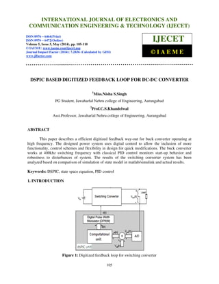
1. INTRODUCTION
Figure 1: Digitized feedback loop for switching converter
INTERNATIONAL JOURNAL OF ELECTRONICS AND
COMMUNICATION ENGINEERING & TECHNOLOGY (IJECET)
ISSN 0976 – 6464(Print)
ISSN 0976 – 6472(Online)
Volume 5, Issue 5, May (2014), pp. 105-110
© IAEME: www.iaeme.com/ijecet.asp
Journal Impact Factor (2014): 7.2836 (Calculated by GISI)
www.jifactor.com
IJECET
© I A E M E
- 2. International Journal of Electronics and Communication Engineering & Technology (IJECET), ISSN 0976 –
6464(Print), ISSN 0976 – 6472(Online), Volume 5, Issue 5, May (2014), pp. 105-110 © IAEME
106
Modern DC power supplies are becoming more efficient, more flexible, less expensive and
smaller. Their enhancement has been achieved by incorporating digital signal controllers into Switch
Mode Power Supply (SMPS) based designs. Buck converters are used when the desired output
voltage is lower than the input voltage. Usually, the non-linear behavior of switch creates control
problem consists of defining the desired nominal operating condition, and then regulating the circuit
so that it stays close to the nominal reference voltage. Use of PID controller improves the steady
state performance and transient response. It is possible to design stable, efficient and ruggedized
SMPS which has faster transient response for dynamically switching loads. [1]
Synchronous buck converters with voltage-mode control and voltage-mode error amplifier
have received great attention in low voltage DC/DC converter applications because they can offer
high efficiency; provide more precise output voltage and also meet the size requirement constraints.
2. DESIGN OF SYNCHRONOUS BUCK CONVERTER
Figure 2: Synchronous buck converter
The designed synchronous buck converter system accepts 9V, 2A and provides 2V,4W
output. The digital PWM signals provided to the switching MOSFETs are operated around 400kHz
frequency. The part of system’s output is feed to the dsPIC based computational unit compromising
of ADC where the digital voltage output obtained is compared with the reference voltage to produce
an error signal.The error signal is further processed to modify the pulse width of DPWM to stabilise
the output.
3. STEADY STATE ANALYSIS OF BUCK CONVERTER
Power electronics converters are system having periodic time variation, because of their
switching operation. In general, state space averaging method models the converter as time
independent system, defined by a unique set of differential equations, capable of representing circuit
waveforms. Therefore, it proves be a convenient approach for designing controllers to be applied to
switched converters [3].The state diagram The source code further stabilises the DC output to around
± 2% of the desired output by incooperating the PID compensation.The digital computation unit used
is using dsPIC33FJ16GS502 instead of using DSP processor for obtaining economical but effficient
solution over analog feedback system,which sufferes variation due to environmental factors ,ageing
[3][7].buck of converter is simulated using matlab/simulink.
- 3. International Journal of Electronics and Communication Engineering & Technology (IJECET), ISSN 0976 –
6464(Print), ISSN 0976 – 6472(Online), Volume 5, Issue 5, May (2014), pp. 105-110 © IAEME
107
Figure 3:Buck converter in ON state[3]
The differential equation for the system for the state variables obtained from figure 3 are
Applying KVL and KCL to the loop;
(1)
(2)
(3)
State equations obtained are:
(4)
(5)
Figure 4:Buck converter in OFF state[3]
- 4. International Journal of Electronics and Communication Engineering & Technology (IJECET), ISSN 0976 –
6464(Print), ISSN 0976 – 6472(Online), Volume 5, Issue 5, May (2014), pp. 105-110 © IAEME
108
Applying KCL and KVL for figure 4
ܮ
ௗಽ ሺ௧ሻ
ௗ௧
ൌ െሾܴ ைே݅ሺݐሻ ܴ݅ሺݐሻ ܸ௨௧ሺݐሻሿ (6)
ܸ௨௧ሺݐሻ െ ܸሺݐሻ െ ݅ ሺݐሻܴ = 0 (7)
The state equations obtained are
ቂ
L 0
0 C
ቃ
ୢ୧ై ሺ୲ሻ
ୢ୲
ୢిሺ୲ሻ
ୢ୲
ൌ
െሾR R ሺR||Rେሻሿ െ
ୖ
ୖାୖి
ୖ
ୖାୖి
െ
ଵ
ୖାୖి
iሺtሻ
Vେሺtሻ
൨ ቂ
0
0
ቃ V ୧୬ሺtሻ (8)
ܸை்ሺݐሻ
݅ூேሺݐሻ
൨ ൌ ቈ
ሾሺܴ||ܴሻሿ
ோ
ோାோ
0 0
݅ሺݐሻ
ܸሺݐሻ
൨ ቂ
0
0
ቃ ܸ ሺݐሻሻ (9)
The state equations are used to obtained the model to be simulated in matlab/simulink.The
buck converter model simulated results are close to actual results.
4. MINIMUM RESOLUTION OF A/D CONVERTER, DIGITAL PWM:
To satisfy specifications for the voltage regulation of output and to limit the oscillation
produced due to fast switching, resolution of the A/D converter has to enable error lower than the
allowed variation of the output voltage ∆V0.
݊ ௗ⁄ ൌ ݅݊ݐሾ݈݃ଶ
ೌೣೌ ⁄
ೝ
.
బ
∆బ
ሿ……….. (1)
Equation (1) gives the minimum number of bits for the A/D converter to meet the design
specifications in terms of the output voltage regulation. For example, if 2% variation.[2]
Digital pulse width modulator (DPWM) produces a discrete set of duty ratio values. This means that
in steady state only a discrete set of output voltage values can be obtained.
݊௪ ݅݊ݐሾ݊ ௗ⁄ ݈݃ଶ ൬
ೝ
ೌೣೌ .⁄
൰ሿ..(2)
From equation (2) reveals that the minimum resolution of the DPWM depends on steady-
state operating conditions in the circuit and the A/D resolution [2].
The dsPIC33FJ16GS502 digital computation unit used in this paper has 10 bit ADC and the
frequency resolution of PWM is 1.04ns.These dsPIC ICs have features like DSP processors.Hence a
comparatively efficient but low cost and lesser complex switching sytem is achieved using dsPIC
IC[1]. The source code incoperates the calculation of PID coefficient to assure close loop stability of
the system. This controller has one pole at the origin and two zeros. The equation PID controller,
shown in Equation (3)
ܩሺ௦ሻ ൌ ܭ
௦
ܭௗሺݏሻ……….(3).
- 5. International Journal of Electronics and Communication Engineering & Technology (IJECET), ISSN 0976 –
6464(Print), ISSN 0976 – 6472(Online), Volume 5, Issue 5, May (2014), pp. 105-110 © IAEME
109
5. EXPERIMENTAL RESULTS
A) Simulated output voltage=2.1v B) Practical Output voltage: 2.080v
C) Simulated PWM: 400 KHz D) Practical pwm_h=391.1khz
E) Practical pwm_l=391.1khz
- 6. International Journal of Electronics and Communication Engineering & Technology (IJECET), ISSN 0976 –
6464(Print), ISSN 0976 – 6472(Online), Volume 5, Issue 5, May (2014), pp. 105-110 © IAEME
110
Table 1: overall result
Parameter Simulink Output Practical output
Output voltage 2.10v 2.080v
PWM frequency 400Khz 391.1KHz
PWM duty cycle 60% 75%
Table 2: Practical parameters obtained
parameter Result
VIN 9V
VOUT 2V
Input Power 18W
Output Power 4W
PWM-H 10.60V,391.1 KHZ
PWM-L 10.60V,391.1 KHZ
6. CONCLUSION
This paper explores digital controlled power supply systems with objective of the achieving
improvements in converter control schemes, system performance over conventional analog control
approaches and cost effectiveness lesser complex system over most popular and efficient DSP
processor. Digital controllers, provides a favorable position to provide basic feedback control as well
as power management functions with lower cost and great flexibility. The design and implementation
400 Khz high frequency buck converter system using dsPIC controller is described.
7. REFERENCES
1. S.V.Patil, T,R,Shukla and P.J. Shah “Modellimg of PID controller based SMPS using
FPGA”IJIRSET journal Vol. 1, Issue 2, December 2012.
2. Aleksandar Prodic, Dragan Maksimovic and Robert W. Erickson, “Design and Implementation of a
Digital PWM Controller for a High-Frequency Switching DC-DC Power Converter” IECON'01:
The 27th Annual Conference of the IEEE Industrial Electronics Society.
3. Vandana Jha, pankaj Rai, “State Space Averaged Modeling of Basic Converter Topologies”,
VSRD-IJEECE, Vol. 2 (8), 2012, 566-575
4. Su, J.H.; Chen, J.J.; Wu, D.S.; “Learning feedback controller design of switching converters via
Matlab/Simulink” Education, IEEE Transactions on, Volume: 45 Issue: 4, Nov. 2002 Page(s): 307
-315.
5. David Freeman, “Digital power for a digital world”, Texas Instruments, 2004.
6. Robert V. White, “Digital Power System Management”, Artesyn Technologies, 2005.
7. A. Prodic and D. Maksimovic, "Digital PWM Controller and Current Estimator for a Low-Power
Master thesis performed in division of Electronic Devices Switching Converter,” IEEE Computers
in Power Electronics 2000, pp. 123-128
8. Muhammad Saad Rahman “Buck Converter Design Issues” Master thesis performed in division of
Electronic Devices
9. Vandana Jha, Dr. Pankaj Rai, Dibya Bharti, “Modelling And Analysis Of Dc-Dc Converter Using
Simulink For Dc Motor Control” International Journal of Electrical Engineering & Technology
(IJEET), Volume 3, Issue 2, 2012, pp. 58 - 68, ISSN Print : 0976-6545, ISSN Online: 0976-6553
10. Ms.Tan Qian Yi, Mr. Gowrishankar Kasilingam and Mr.Raman Raghuraman, “Optimal-Tuning of
PID Power System Stabilizer in Simulink Environment for A Synchronous Machine” International
Journal of Electrical Engineering & Technology (IJEET), Volume 4, Issue 1, 2013, pp. 115 - 123,
ISSN Print : 0976-6545, ISSN Online: 0976-6553

![International Journal of Electronics and Communication Engineering & Technology (IJECET), ISSN 0976 –
6464(Print), ISSN 0976 – 6472(Online), Volume 5, Issue 5, May (2014), pp. 105-110 © IAEME
106
Modern DC power supplies are becoming more efficient, more flexible, less expensive and
smaller. Their enhancement has been achieved by incorporating digital signal controllers into Switch
Mode Power Supply (SMPS) based designs. Buck converters are used when the desired output
voltage is lower than the input voltage. Usually, the non-linear behavior of switch creates control
problem consists of defining the desired nominal operating condition, and then regulating the circuit
so that it stays close to the nominal reference voltage. Use of PID controller improves the steady
state performance and transient response. It is possible to design stable, efficient and ruggedized
SMPS which has faster transient response for dynamically switching loads. [1]
Synchronous buck converters with voltage-mode control and voltage-mode error amplifier
have received great attention in low voltage DC/DC converter applications because they can offer
high efficiency; provide more precise output voltage and also meet the size requirement constraints.
2. DESIGN OF SYNCHRONOUS BUCK CONVERTER
Figure 2: Synchronous buck converter
The designed synchronous buck converter system accepts 9V, 2A and provides 2V,4W
output. The digital PWM signals provided to the switching MOSFETs are operated around 400kHz
frequency. The part of system’s output is feed to the dsPIC based computational unit compromising
of ADC where the digital voltage output obtained is compared with the reference voltage to produce
an error signal.The error signal is further processed to modify the pulse width of DPWM to stabilise
the output.
3. STEADY STATE ANALYSIS OF BUCK CONVERTER
Power electronics converters are system having periodic time variation, because of their
switching operation. In general, state space averaging method models the converter as time
independent system, defined by a unique set of differential equations, capable of representing circuit
waveforms. Therefore, it proves be a convenient approach for designing controllers to be applied to
switched converters [3].The state diagram The source code further stabilises the DC output to around
± 2% of the desired output by incooperating the PID compensation.The digital computation unit used
is using dsPIC33FJ16GS502 instead of using DSP processor for obtaining economical but effficient
solution over analog feedback system,which sufferes variation due to environmental factors ,ageing
[3][7].buck of converter is simulated using matlab/simulink.](data:image/gif;base64,R0lGODlhAQABAIAAAAAAAP///yH5BAEAAAAALAAAAAABAAEAAAIBRAA7)