This document provides an overview and outline of an equipment service manual. It is divided into 8 sections that cover general information, removal/installation procedures, various mechanical systems, electrical systems, and the mast/forklift components. The foreword explains the structure and purpose of the manual to aid technicians in performing repairs correctly. Key sections include specifications, safety hints, troubleshooting guides, and instructions for disassembly/assembly of parts. The document also provides guidance on how to read part numbers and file pages in the proper order.
Hyundai brj series forklift truck service repair manual
1. CONTENTS
SECTION 1 GENERAL
Group 1 Safety hints ---------------------------------------------------------------------------------------------------- 1-1
Group 2 Specifications ------------------------------------------------------------------------------------------------ 1-5
Group 3 Periodic replacement ------------------------------------------------------------------------------------- 1-16
SECTION 2 REMOVAL & INSTALLATION
Group 1 Structure -------------------------------------------------------------------------------------------------------- 2-1
Group 2 Removal and Installation of Unit ------------------------------------------------------------------- 2-2
SECTION 3 POWER TRAIN SYSTEM
Group 1 Structure and operation --------------------------------------------------------------------------------- 3-1
Group 2 Troubleshooting --------------------------------------------------------------------------------------------- 3-4
Group 3 Disassembly and assembly -------------------------------------------------------------------------- 3-6
SECTION 4 BRAKE SYSTEM
Group 1 Structure and function ----------------------------------------------------------------------------------- 4-1
SECTION 5 STEERING SYSTEM
Group 1 Structure and function ----------------------------------------------------------------------------------- 5-1
SECTION 6 HYDRAULIC SYSTEM
Group 1 Structure and function ----------------------------------------------------------------------------------- 6-1
Group 2 Operational checks and troubleshooting ------------------------------------------------------- 6-20
Group 3 Disassembly and assembly --------------------------------------------------------------------------- 6-24
SECTION 7 ELECTRICAL SYSTEM
Group 1 Component location -------------------------------------------------------------------------------------- 7-1
Group 2 Electrical circuit ---------------------------------------------------------------------------------------------- 7-2
Group 3 Electric components -------------------------------------------------------------------------------------- 7-3
SECTION 8 MAST
Group 1 Structure -------------------------------------------------------------------------------------------------------- 8-1
Group 2 Operational checks and troubleshooting ------------------------------------------------------- 8-3
Group 3 Adjustment ----------------------------------------------------------------------------------------------------- 8-6
Group 4 Removal and installation -------------------------------------------------------------------------------- 8-9
2. 0-1
FOREWORD
1. STRUCTURE
This service manual has been prepared as an aid to improve the quality of repairs by giving the
serviceman an accurate understanding of the product and by showing him the correct way to perform
repairs and make judgements. Make sure you understand the contents of this manual and use it to
full effect at every opportunity.
This service manual mainly contains the necessary technical information for operations performed in
a service workshop.
For ease of understanding, the manual is divided into the following sections.
SECTION 1 GENERAL
This section gives the general information of the machine and explains the safety hints for
maintenance.
SECTION 2 REMOVAL & INSTALLATION OF UNIT
This section explains the procedures and techniques of removal and installation of each component.
SECTION 3 POWER TRAIN SYSTEM
This section explains the structure of the transmission as well as control valve and drive axle.
SECTION 4 BRAKE SYSTEM
This section explains the brake piping, each component and operation.
SECTION 5 STEERING SYSTEM
This section explains the structure of the steering unit, priority valve, trail axle as well as steering
circuit and operation.
SECTION 6 HYDRAULIC SYSTEM
This section explains the structure of the gear pump, main control valve as well as work equipment
circuit, each component and operation.
SECTION 7 ELECTRICAL SYSTEM
This section explains the electrical circuit and each component.
It serves not only to give an understanding electrical system, but also serves as reference material for
troubleshooting.
SECTION 8 MAST
This section explains the structure of mast, carriage, backrest and forks.
The specifications contained in this service manual are subject to change at any time and without any
advance notice. Contact your HYUNDAI distributor for the latest information.
3. 0-2
Revised edition mark(①②③…)
When a manual is revised, an edition mark is
recorded on the bottom outside corner of the
pages.
R
Revisions
Revised pages are shown at the list of revised
pages on the between the contents page and
section 1 page.
Symbols
So that the shop manual can be of ample
practical use, important places for safety and
quality are marked with the following symbols.
2. HOW TO READ THE SERVICE MANUAL
Distribution and updating
Any additions, amendments or other changes will
be sent to HYUNDAI distributors.
Get the most up-to-date information before you
start any work.
Filing method
See the page number on the bottom of the
page.
File the pages in correct order.
Following examples shows how to read the
page number.
Example 1
2 - 3
Item number(2. Structure and
Function)
Consecutive page number for
each item.
Additional pages : Additional pages are
indicated by a hyphen(-) and number after the
page number. File as in the example.
1.
2.
3.
Symbol Item Remarks
Special safety precautions are
necessary when performing the
work.
Extra special safety precautions
are necessary when performing
the work because it is under
internal pressure.
Special technical precautions or
other precautions for preserving
standards are necessary when
performing the work.
Safety
Caution
※
10 - 4
10 - 4 - 1
10 - 4 - 2
10 - 5
Added pages
4. 0-3
3. CONVERSION TABLE
Method of using the Conversion Table
The Conversion Table in this section is provided to enable simple conversion of figures. For details of
the method of using the Conversion Table, see the example given below.
Example
Method of using the Conversion Table to convert from millimeters to inches
Convert 55mm into inches.
Locate the number 50in the vertical column at the left side, take this as ⓐ, then draw a
horizontal line from ⓐ.
Locate the number 5in the row across the top, take this as ⓑ, then draw a perpendicular line
down from ⓑ.
Take the point where the two lines cross as ⓒ. This point ⓒ gives the value when converting
from millimeters to inches. Therefore, 55mm = 2.165 inches.
Convert 550mm into inches.
The number 550 does not appear in the table, so divide by 10(Move the decimal point one place
to the left) to convert it to 55mm.
Carry out the same procedure as above to convert 55mm to 2.165 inches.
The original value(550mm) was divided by 10, so multiply 2.165 inches by 10(Move the decimal
point one place to the right) to return to the original value.
This gives 550mm = 21.65 inches.
1.
2.
(1)
(2)
(3)
(1)
(2)
(3)
Millimeters to inches 1mm = 0.03937 in
ⓑ
ⓐ
0 1 2 3 4 5 6 7 8 9
0 0.039 0.079 0.118 0.157 0.197 0.236 0.276 0.315 0.354
10 0.394 0.433 0.472 0.512 0.551 0.591 0.630 0.669 0.709 0.748
20 0.787 0.827 0.866 0.906 0.945 0.984 1.024 1.063 1.102 1.142
30 1.181 1.220 1.260 1.299 1.339 1.378 1.417 1.457 1.496 1.536
40 1.575 1.614 1.654 1.693 1.732 1.772 1.811 1.850 1.890 1.929
50 1.969 2.008 2.047 2.087 2.126 2.165 2.205 2.244 2.283 2.323
60 2.362 2.402 2.441 2.480 2.520 2.559 2.598 2.638 2.677 2.717
70 2.756 2.795 2.835 2.874 2.913 2.953 2.992 3.032 3.071 3.110
80 3.150 3.189 3.228 3.268 3.307 3.346 3.386 3.425 3.465 3.504
90 3.543 3.583 3.622 3.661 3.701 3.740 3.780 3.819 3.858 3.898
ⓒ
9. TEMPERATURE
Fahrenheit-Centigrade Conversion.
A simple way to convert a fahrenheit temperature reading into a centigrade temperature reading or vice verse
is to enter the accompanying table in the center or boldface column of figures.
These figures refer to the temperature in either Fahrenheit or Centigrade degrees.
If it is desired to convert from Fahrenheit to Centigrade degrees, consider the center column as a table of
Fahrenheit temperatures and read the corresponding Centigrade temperature in the column at the left.
If it is desired to convert from Centigrade to Fahrenheit degrees, consider the center column as a table of
Centigrade values, and read the corresponding Fahrenheit temperature on the right.
0-8
。
C 。
F 。
C 。
F 。
C 。
F 。
C 。
F
-40.4 -40 -40.0 -11.7 11 51.8 7.8 46 114.8 27.2 81 117.8
-37.2 -35 -31.0 -11.1 12 53.6 8.3 47 116.6 27.8 82 179.6
-34.4 -30 -22.0 -10.6 13 55.4 8.9 48 118.4 28.3 83 181.4
-31.7 -25 -13.0 -10.0 14 57.2 9.4 49 120.2 28.9 84 183.2
-28.9 -20 -4.0 -9.4 15 59.0 10.0 50 122.0 29.4 85 185.0
-28.3 -19 -2.2 -8.9 16 60.8 10.6 51 123.8 30.0 86 186.8
-27.8 -18 -0.4 -8.3 17 62.6 11.1 52 125.6 30.6 87 188.6
-27.2 -17 1.4 -7.8 18 64.4 11.7 53 127.4 31.1 88 190.4
-26.7 -16 3.2 -6.7 20 68.0 12.8 55 131.0 32.2 90 194.0
-26.1 -15 5.0 -6.7 20 68.0 12.8 55 131.0 32.2 90 194.0
-25.6 -14 6.8 -6.1 21 69.8 13.3 56 132.8 32.8 91 195.8
-25.0 -13 8.6 -5.6 22 71.6 13.9 57 134.6 33.3 92 197.6
-24.4 -12 10.4 -5.0 23 73.4 14.4 58 136.4 33.9 93 199.4
-23.9 -11 12.2 -4.4 24 75.2 15.0 59 138.2 34.4 94 201.2
-23.3 -10 14.0 -3.9 25 77.0 15.6 60 140.0 35.0 95 203.0
-22.8 -9 15.8 -3.3 26 78.8 16.1 61 141.8 35.6 96 204.8
-22.2 -8 17.6 -2.8 27 80.6 16.7 62 143.6 36.1 97 206.6
-21.7 -7 19.4 -2.2 28 82.4 17.2 63 145.4 36.7 98 208.4
-21.1 -6 21.2 -1.7 29 84.2 17.8 64 147.2 37.2 99 210.2
-20.6 -5 23.0 -1.1 35 95.0 21.1 70 158.0 51.7 125 257.0
-20.0 -4 24.8 -0.6 31 87.8 18.9 66 150.8 40.6 105 221.0
-19.4 -3 26.6 0 32 89.6 19.4 67 152.6 43.3 110 230.0
-18.9 -2 28.4 0.6 33 91.4 20.0 68 154.4 46.1 115 239.0
-18.3 -1 30.2 1.1 34 93.2 20.6 69 156.2 48.9 120 248.0
-17.8 0 32.0 1.7 35 95.0 21.1 70 158.0 51.7 125 257.0
-17.2 1 33.8 2.2 36 96.8 21.7 71 159.8 54.4 130 266.0
-16.7 2 35.6 2.8 37 98.6 22.2 72 161.6 57.2 135 275.0
-16.1 3 37.4 3.3 38 100.4 22.8 73 163.4 60.0 140 284.0
-15.6 4 39.2 3.9 39 102.2 23.3 74 165.2 62.7 145 293.0
-15.0 5 41.0 4.4 40 104.0 23.9 75 167.0 65.6 150 302.0
-14.4 6 42.8 5.0 41 105.8 24.4 76 168.8 68.3 155 311.0
-13.9 7 44.6 5.6 42 107.6 25.0 77 170.6 71.1 160 320.0
-13.3 8 46.4 6.1 43 109.4 25.6 78 172.4 73.9 165 329.0
-12.8 9 48.2 6.7 44 111.2 26.1 79 174.2 76.7 170 338.0
-12.2 10 50.0 7.2 45 113.0 26.7 80 176.0 79.4 172 347.0
10. SECTION 6 HYDRAULIC SYSTEM
Group 1 Structure and function ------------------------------------------------------------------------------------ 6-1
Group 2 Operational checks and troubleshooting -------------------------------------------------------- 6-20
Group 3 Disassembly and assembly --------------------------------------------------------------------------- 6-24
11. 6-1
GROUP 1 STRUCTURE AND FUNCTION
SECTION 6 HYDRAULIC SYSTEM
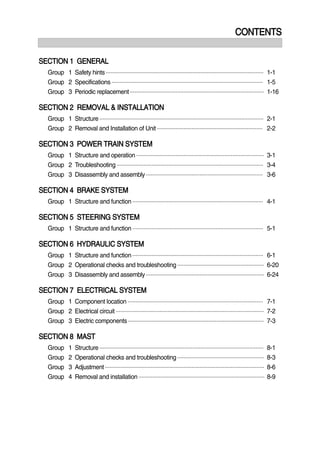
1. HYDRAULIC CIRCUIT (14/16BRJ-7)
4
3
5
2
6
8
M
1
7
9
BRJ7HS01
1 Hydraulic pump
2 Main control valve
3 Lift cylinder
4 Down safety valve
5 Tilt cylinder
6 Reach cylinder
7 Return filter
8 Suction strainer
9 Hydraulic tank
13. 6-3
m5
m6
emergency
lowering DW3
DW2
m2
m1
m4
m3
130bar
m7
m8
130bar
4
3
5
2
6
8
M
1
7
9
BRJ7HS02
WHEN THE LIFT CONTROL LEVER IS IN THE LIFT POSITION (14/16BRJ-7)
1)
When the lift control lever is pulled back, the m1 valve on the lift block is moves to open position.
The oil from hydraulic gear pump(1) flows into main control valve(2) and then goes to the large
chamber of lift cylinder(3).
The oil from the small chamber of lift cylinder(3) returns to hydraulic oil tank(9) at the same time.
When this happens, the forks go up.
14. 6-4
4
3
5
2
6
8
M
1
7
9
BRJ7HS08
WHEN THE LIFT CONTROL LEVER IS IN THE LIFT POSITION (20/25BRJ-7)
When the lift control lever is pulled back, the m1 valve on the lift block is moves to open position.
The oil from hydraulic gear pump(1) flows into main control valve(2) and then goes to the large
chamber of lift cylinder(3).
17. 6-7
m5
m6
emergency
lowering DW3
DW2
m2
m1
130bar
m7
m8
130bar
4
3
5
2
6
8
M
1
7
9
m4
m3
BRJ7HS04
WHEN THE TILT CONTROL LEVER IS IN THE BACKWARD POSITION
3)
When the tilt control lever is pulled backward, the spool on the second block is moved to tilt
backward position.
The oil from hydraulic gear pump(1) flows into main control valve(2) and then goes to the large
chamber of tilt cylinder(5).
The oil at the small chamber of tilt cylinder(5) returns to hydraulic tank(9) at the same time.
18. 6-8
m5
m6
G10
emergency
lowering DW3
DW2
m2
m1
H
P
R
MP
LS
DBV
G16
m4
m3
130bar
A B
m7
m8
G25
A B
A B
T
190 bar
130bar
(at 40lpm)
4
3
5
2
6
8
14/16BRJ ONLY
M
1
7
9
BRJ7HS05
WHEN THE TILT CONTROL LEVER IS IN THE FORWARD POSITION
4)
When the tilt control lever is pushed forward, the spool on the second block is moved to tilt forward
position.
The oil from hydraulic gear pump(1) flows into main control valve(2) and then goes to the small
chamber of tilt cylinder(5).
The oil at the large chamber of tilt cylinder(5) returns to hydraulic tank(9) at the same time.
19. 6-9
m5
m6
G10
emergency
lowering DW3
DW2
m2
m1
H
P
R
MP
LS
DBV
G16
m4
m3
130bar
A B
m7
m8
G25
A B
A B
T
190 bar
130bar
(at 40lpm)
4
3
5
2
6
8
14/16BRJ ONLY
M
1
7
9
BRJ7HS06
WHEN THE REACH CONTROL LEVER IS IN THE FORWARD (REACH OUT) POSITION
5)
When the reach control lever is pushed forward, the spool on the third block is moved to reach out
position.
The oil from hydraulic gear pump(1) flows into main control valve(2) and then goes to the large
chamber of reach cylinder(6).
The oil at the small chamber of reach cylinder(6) returns to hydraulic tank(9) at the same time.
When this happens, the mast reaches out.
20. 6-10
4
3
5
2
6
8
M
1
7
9
BRJ7HS07
WHEN THE REACH CONTROL LEVER IS IN THE BACKWARD (REACH IN) POSITION
6)
When the reach control lever is pulled backward, the spool on the third block is moved to reach in
position.
The oil from hydraulic gear pump(1) flows into main control valve(2) and then goes to the small
chamber of reach cylinder(6).
The oil at the large chamber of reach cylinder(6) returns to hydraulic tank(9) at the same time.
When this happens, the mast reaches in.
21. Thank you very much for
your reading. Please Click
Here. Then Get COMPLETE
MANUAL. NO WAITING
NOTE:
If there is no response to
click on the link above,
please download the PDF
document first and then
click on it.
22. 6-11
2. HYDRAULIC GEAR PUMP
STRUCTURE
1
10
12
3 14
13
7
8
2
5
4
6
9
11
9
6
8
7
11
BRJ7HS19
1 Mounting frange
2 End cover
3 Gear housing
4 Drive gear
5 Idler shaft
6 Bearing block
7 Backup ring
8 Seal
9 O-ring
10 Shaft seal
11 Dowel pin
12 Start ring
13 Socket head bolt
14 Spring washer
1)
OPERATION
This pump comprises of an rear cover, a body, bushings and a housing bolted together with bolts.
The gear journals are supported in side plate within pressure balanced bushings to give high
volumetric and mechanical efficiencies.
2)
23. 6-12
3. MAIN CONTROL VALVE
STRUCTURE (3 Spool)
1)
6
7
2
6
12
17
19
5
10
19
17
17
4
4
4
4-2
4-3
4-5
4-1
4-4
2-3
2-2
2-5
2-1
2-5
2-4
2
4
4
3
8
19
18
18
18
19
1
2
15
16
14
14
15
16
13
H R
P
A
B
A
B
BRJ7HS12A
1 Main block
2 Solenoid valve (Lift)
2-1 EVI coil
2-2 Washer
2-3 Lock washer
2-4 Black plug
2-5 O-ring
3 Tilt block
4 Solenoid valve
4-1 Coil
4-2 Disc
4-3 Circlip
4-4 Black plug
4-5 O-ring
5 Roll pin
6 Adapter
7 Head screw
8 Reach block
10 Roll pin
Port name
Inlet port
Outlet port
Work port
Work port
Size
1 1/16-12UN
1 1/16-12UN
1 1/16-12UN
9/16-18 UNF
Port
P
R
H
A, B
11 Adapter
12 Head screw
13 End block
14 Tension rod
15 Shape washer
16 Hexagon nut
17 O-ring
18 O-ring
19 O-ring