SlideShare une entreprise Scribd logo
1  sur  9
Télécharger pour lire hors ligne
Pratik Tiwari et al Int. Journal of Engineering Research and Applications www.ijera.com
ISSN : 2248-9622, Vol. 4, Issue 3( Version 6), March 2014, pp.58-66
www.ijera.com 58 | P a g e
Influence of Wall Position on Flow Characteristics of an
Impinging Jet
Pratik Tiwari, P. Mahathi, N. R. Choudhury and Vinayak Malhotra*
(Department of Aerospace Engineering, SRM University, Kancheepuram District, Tamil Nadu, INDIA)
ABSTRACT
The study intends physical insight into heterogeneous phenomena of efflux from a small opening impinging on
a surface. The work aims at understanding the role of wall location and orientation on flow characteristics of an
impinging jet. Experiments were performed on an existing cascade tunnel with flow ejected at a velocity of 37
m/s from a small opening of (30 cm × 9 cm) and corresponding flow features were analyzed. Results show that
outside the core region, the flow experiences a monotonic reduction with increase in distance along streamline
and radial direction. The orientation of wall is more efficient in bringing substantial change when placed closer
to the exit (low velocity losses). The wall orientation primarily governs the chances of strong flow deflection or
back flow losses. Wall placed far away from exit results in diminishing returns with a critical value beyond
which the flow characteristics become insensitive of wall orientation.
Keywords - Efflux, shear interaction, vortices, wall jets, wall orientation, wall location.
I. INTRODUCTION
The study of jet efflux from a small opening
is a phenomenon of practical and functional
significance for space research activities. The subject
involves mass and heat transfer and is widely
characterized as: Free and Wall Jet. This
classification is based on presence of a surface (i.e.
wall) against the jet expelled. While in free jet
configuration, jets exit a nozzle or tube into a
stationary or moving fluid (same or different), wall
jet refers to a stream of fluid blown normally or
tangentially along a wall (subjected to position of
wall). The free and wall jets are broadly encountered
in nature and cover wide range of applications.
Examples include aircraft gas turbine engines, liquid
and solid rocket motors, boundary-layer separation
control over a wing, film cooling on turbine blades,
etc. In the wall jets, an efflux of liquid or gaseous
when released against surface large amounts of mass
and thermal energy transfers between the surface and
the fluid takes place. Figure 1(a) shows the schematic
of a free jet issued from a small opening. In free jet
mode as the fluid moves downstream, it interacts
with the surrounding fluid and its speed drops.
Consequently, the efflux of jet rifts into two distinct
regions viz., a region near the centerline where fluid
interacts less with the surrounding medium and
maintains nearly its initial speed some distance
downstream.
This region in which the speed is nearly
that of the exit is termed as the potential core or
the core region (see fig. 1(a) & (b)). The length of
core region in jets under different conditions is a
prominent factor.
(a)
(b)
Figure 1: (a) Schematic of a free jet (b) Pictorial
view of a free jet.
Next is region outside the core where fluid
comprehensively interacts with the surrounding fluid.
This region is known as the entrainment region and it
is identified by drastic change in flow characteristics
(see Fig. 1(b)). The presence of a surface in front of a
jet is very likely to alter the flow characteristics. This
surface when placed at different locations and
orientations will have significant implications.
RESEARCH ARTICLE OPEN ACCESS
Pratik Tiwari et al Int. Journal of Engineering Research and Applications www.ijera.com
ISSN : 2248-9622, Vol. 4, Issue 3( Version 6), March 2014, pp.58-66
www.ijera.com 59 | P a g e
Following the classical work of Glauert
(1956) highlighting the flow due to a jet spreading
out over a plane surface. In the last five decades
research works have contributed significantly to the
advancement in understanding of the free jets. The
contributions have been reported in several reviews
like Gardon and Akfirat (1966), Kercher and
Tabakoff (1970), Sparrow and Alhomoud (1984),
Gau and Chung (1991), Gori and Bossi (2000). The
works provide an excellent review on the
developments up to the end of the century.
In the last decade appreciable advancements
have occurred. Roy and Patel (2003) studied the
dominant fluid-thermal characteristics of a pair of
rectangular air jets impinging on an inclined surface.
Heat transfer modes and flow characteristics were
studied with eight different Reynolds numbers
ranging from 500 to 20000. Aldabbagha and
Mohamadb (2009) carried out a three-dimensional
numerical study to determine the flow and heat
transfer characteristics of impinging laminar array of
square jets on a moving surface. They stated that a
rather complex flow field with horseshoe vortices
formed around the first column of jets due to the
cross flow created by the moving surface. The
velocity ratio of the moving plate increases the cross
flow as a result a ground vortex cannot form in front
of the second and third column jets compared with
the case of fix surface.
In recently, Azam et al., (2013) studied
pressure distributions and oil flow on the plate to
figure out the flow structures for the rectangular
nozzles by comparing three-dimensional calculations
to the experiments. They investigated at three
different aspect ratio under-expanded impinging jet
issued from rectangular nozzle. The results stated that
the flow is separated on the impinging plate from
center point toward outside and that the flow on the
plate avoids the high-pressure areas. San and Chen
(2014) explored the effects of jet-to-jet spacing and
jet height on heat transfer characteristics of an
impinging jet array. Tiwari et al., (2014) carried out
experiments to investigate the effect of wall location
on flow characteristics of an impinging jet and the
core region. The work showed that increase in
centerline wall location enhances the velocity losses.
Wall location near to exit causes strong deflection of
flow resulting formation of vortices with prominent
chances of back flow. Furthermore, for a fixed wall
location, increase in radial distance enhances the
velocity losses, but it results in diminishing returns
beyond a critical value. Although much has been
done but complexity of the problem has prevented a
complete understanding due to interaction between
flow, heat and mass transfer.
Therefore, a systematic study is needed to
understand mechanisms controlling the behavior of
jets and their flow characteristics.
In the light of above-mentioned works, the
work primarily focuses on flow characteristics of an
impinging jet against varying wall location and
orientation. This aspect of jets is yet to be
comprehensively explored. Hence, a systematic study
is needed to understand mechanisms controlling the
behavior of jets when impinging on a wall placed at
different locations and orientations besides the one
open to atmosphere or without any wall. The interest
in this class of problems is specifically driven by the
need to have better understanding of fluid and
thermal characteristics of jets. To address the above
mentioned issue, the present work
1. Experimentally explores the effects of surface
location and orientation on flow characteristics of
an impinging jet.
2. Analyzes the role of key controlling parameters.
II. EXPERIMENTAL SETUP AND SOLUTION
METHODOLOGY
A simple apparatus (Fig. 2(a)) was adapted
for this study. The apparatus consisted of a) cascade
tunnel (Fig. 2(b) base made of mild steel b) a Pitot
tube (Fig. 2(a)) and c) Micro Manometer (Fig. 2(c)).
The cascade tunnel issues a free air jet using a
centrifugal blower with a velocity of 37 m/s. The
efflux is from a small rectangular opening
(dimensions 30 cm × 9 cm (Fig. 2(d)) into the air in a
quiescent room. The flow characteristics are
determined by establishing the pressure balance
between dynamic pressure and the hydrostatic
pressure.
(a)
(b) (c)
Figure 2: Pictorial view of (a) complete experimental
setup (b) side view of cascade tunnel (c) micro
manometer.
Pratik Tiwari et al Int. Journal of Engineering Research and Applications www.ijera.com
ISSN : 2248-9622, Vol. 4, Issue 3( Version 6), March 2014, pp.58-66
www.ijera.com 60 | P a g e
The dynamic pressure is measured using
Pitot tube (exposed directly to the flow and stagnates
it at surface measuring total pressure, the static holes
are at the center and side of the tube measuring static
pressure and the dynamic pressure is difference of the
two pressures). The micro manometer calculates the
hydrostatic pressure due to change in elevation of the
fluid used (here distilled water) owing to different
dynamic pressures under different conditions. The
micro manometer exhibits an accuracy level of 0.001
cm height of the fluid and can measure the
differential pressure up till the range of 300 mm of
the used fluid. The dynamic pressure is equated to the
hydrostatic pressure and the flow velocity (kinetic
energy) is measured. It is important to note that all
the readings were taken systematically in proper time
interval and all the reading taken here represent the
repeatability of results obtained. The wall used in the
study is a rectangular cardboard surface with
dimensions of 180 cm × 120 cm × 1 cm. The flow is
turbulent and the effect was noted in fluctuations in
the reading, so for every reading taken here the
average repeated value with was accounted. The flow
velocity is obtained by equating the dynamic head to
pressure head obtained by the liquid height change
as:
21
( ) (1)
2
a l 1 oV g h h  
From equation (1), the flow velocity “V” is
determined as:
2 ( ) (2)l
1 o
a
V g h h


 
Where
a Density of air (Kg/m3
)
l Density of water (Kg/m3
)
V Flow velocity (m/s)
g Gravitational acceleration (m/s2
)
0h Reading corresponding to zero differtial
pressure
1 0h h Liquid head corresponding to the
dynamic head
Wϴ Wall orientation
D Equivalent diameter of a circular exit
(1D =18.54 cm)
It is important to note that the density of
liquid (here distilled water) depends on the place of
use of the manometer (the atmospheric pressure and
temperature at the time and place of use). While, the
density of air can be calculated using the state
relations for air for corresponding pressure and
temperature.
III. RESULTS
A parametric experimental study was carried
out to study the flow characteristics of a jet issued
from a small opening and impinging on a wall placed
normal at different locations and orientations. The
effect was investigated by placing the wall placed at
three different locations viz. far away from exit (18D
& 15D), at an intermediate distance (10D) and at
locations very close to exit (2D and 5D) and further
varying orientation of wall in capacity of horizontal,
vertical, 30o
, 45o
, 60o
against the efflux. Here, „D‟
normalizes the streamline distance and all the
readings were taken in folds of „D‟. It must be noted
that „D‟ represents the equivalent diameter of a
circular exit when compared to the exit of cascade
tunnel (rectangular). First, the results obtained from
the experimental setup were validated with the
benchmark subject of flow characteristics of a free
jet.
Figure 3 shows the variation of normalized
centerline velocity as a function of normalized
streamline distance for a free jet. The exit velocities
at different locations are normalized by maximum
velocity (here, 37 m/s) and the streamline distance is
normalized by the equivalent circular diameter „D‟.
Results show that the flow characteristics exhibit a
monotonically reducing behavior with increment in
streamline distance.
Figure 3: Variation of normalized centerline velocity
as a function of normalized streamline distance for a
free jet.
Looking at the plot one can note that the as the jet
exits the tunnel, there is drastic loss of flow velocity
(kinetic energy) with increase in streamline distance.
The core region is seen to extend till 3 units.
Alongside the axial variation of a free jet, the
variation of flow velocity in radial direction at
various orientations (at differential of 5 mm) is
investigated.
Centreline distance (x/D)
Vx/Vcmax.
0 2 4 6 8 10 12 14 16 18
0
0.2
0.4
0.6
0.8
1
Vx
Centreline distance (x/D)
Vx/Vcmax.
0 2 4 6 8 10 12 14 16 18
0
0.2
0.4
0.6
0.8
1
Vcmax.
Pratik Tiwari et al Int. Journal of Engineering Research and Applications www.ijera.com
ISSN : 2248-9622, Vol. 4, Issue 3( Version 6), March 2014, pp.58-66
www.ijera.com 61 | P a g e
Figure 4: Variation of normalized radial velocity as a
function of radial distance for a free jet.
Figure 4 shows the variation of normalized
velocity with distance in radial direction at axial
locations of 2D, 5D, 10D and 18D respectively.
Interestingly, a trend similar to variation in axial
direction is observed in radial direction as well. As
expected, the flow velocity reduces with increase in
radial distance subjected to width of core region (here
noted as 3 cm). Looking at the profiles it was noticed
that, when the reading is taken very close to exit
(here 2D), the flow lies in core region and with
increase in distance suddenly comes out of it and
velocity falls drastically.
When the same trend was introspected at
5D, the maximum velocity (here at centerline) was
found lower than at 2D. However a sudden drop in
radial velocity was noted beyond some distance as
the flow moves out of core region. While, at an
intermediate distance of 10D, the flow is already out
of core regime and is in entrainment region thus an
overall sudden drop in flow velocity is seen.
Furthermore, as the distance in radial direction
increases, unlike wall placed closer to exit, here flow
velocity reports a gradual drop.
Similarly, at location far away from exit
(here 18D), the trend of maximum velocity being
lower with axial distance is followed alongside the
gradual drop in flow velocity with increase in radial
distance. The reason for above mentioned changes in
axial and radial direction can be attributed to the
shear interaction with surroundings leading to strong
energy conversions. The length and width of core
region dictates the velocity loss at different positions.
Since from the results obtained it is evident that the
experimental setup predicts correct results as
preceding theories substantiates, the study was
extended to investigate the effect of presence of a
wall at different axial locations and orientations on
flow characteristics.
First the wall was placed in centerline
against the flow at three different locations viz., very
near to exit (5D), at an intermediate distance (10D),
at a location far away from the exit (18D) in capacity
of horizontal, vertical, 30o
, 60o
, 90o
orientations
respectively.
Figure 5 shows variation of normalized
centerline velocity as a function of wall location and
orientation in comparison to maximum velocity. One
can note that, when the wall is located far from exit
(see Fig. 5(a)) with increment in orientation the
velocity reduces. The centerline velocity at 18D is
seen lower than maximum indicating the loss of
kinetic energy.
(a)
(b)
0 5 10 15 20 25
0
0.2
0.4
0.6
0.8
1
x = 5D
0 5 10 15 20 25
0
0.2
0.4
0.6
0.8
1
x = 2D
0 5 10 15 20 25
0
0.2
0.4
0.6
0.8
1
x = 10D
0 5 10 15 20 25
0
0.2
0.4
0.6
0.8
1
x = 15D
Radial distance (cm)
Vy
/Vcmax.
0 5 10 15 20 25
0
0.2
0.4
0.6
0.8
1
Vcmax.
0 2 4 6 8 10 12 14
0.4
0.6
0.8
1
W
= 45o
0 2 4 6 8 10 12 14
0.4
0.6
0.8
1
W
= 60
o
0 2 4 6 8 10 12 14
0.4
0.6
0.8
1
W= 90
o
Wall = 18D
Centreline distance (x/D)
Vx
/Vcmax.
0 2 4 6 8 10 12 14
0.4
0.5
0.6
0.7
0.8
0.9
1
W
= 0
o
0 2 4 6 8 10 12 14
0.4
0.6
0.8
1
Vcmax.
0 2 4 6 8 10 12 14
0.4
0.6
0.8
1
W
= 30o
0 1 2 3 4 5 6
0.6
0.7
0.8
0.9
1
W= 0o
0 1 2 3 4 5 6
0.6
0.7
0.8
0.9
1
W= 30o
0 1 2 3 4 5 6
0.6
0.7
0.8
0.9
1
W
= 45o
0 1 2 3 4 5 6
0.6
0.7
0.8
0.9
1
W
= 60o
0 1 2 3 4 5 6
0.6
0.7
0.8
0.9
1
W
= 90
o
0 1 2 3 4 5 6
0.6
0.7
0.8
0.9
1
Centreline distance (x/D)
Vx
/Vcmax.
0 1 2 3 4 5 6
0.6
0.7
0.8
0.9
1
Vcmax.
Wall = 10D
Pratik Tiwari et al Int. Journal of Engineering Research and Applications www.ijera.com
ISSN : 2248-9622, Vol. 4, Issue 3( Version 6), March 2014, pp.58-66
www.ijera.com 62 | P a g e
(c)
Figure 5: Variation of normalized centerline velocity
as a function of wall orientation for wall located at
(a) 18D (b) 10D (c) 5D.
This loss of flow velocity is more when the
wall is placed in vertical orientation however when
kept horizontal or closer (here till 30o
) the effect
more or less is same.
This dictates that up to a fixed wall
orientation the effect of shear interaction is within a
closer range but as wall orientation changes beyond
to vertical, it behaves as a case of free jet and
significant losses are noted. Increased wall
orientation increases the induced loss in flow
velocity. Interestingly, at certain centerline distance
the velocity profiles converges to corroborate the
loss. For present case, till centerline distance of 3
units, the flow velocity loss is lower for all profiles
indicating the presence of core region. Following the
core region, further increment results sharp drop in
velocity profiles. In this work, we refer to the point
up-till which the core region exist in streamline
direction as “VRM-PPT point” (Here 3 units= ~ 55
cm). A trend almost similar to far located wall (18D)
is noted at a location of 10D. Beyond “VRM-PPT
point” sharp drop in flow velocities is noted. The
flow profiles are seen merging at centerline distance
of 4 units. However, in this case when wall is placed
parallel or is in vertical orientation to the flow the
loss is lower than wall orientation in the range of (0-
30o
). For wall located at 10D the applicability of the
flow can be more when wall is close to or vertically
oriented. For the case when wall is located closer to
exit (5D), the study was extended only for two
orientations viz., horizontal and 30o
.
Expectedly, the centerline velocity is more
and the flow is mainly confided in the core region. A
crossover in flow velocity profiles is noted at a
streamline distance of 1.5 cm. Here, the results
strongly pronounce that when wall is located far
away and orientated in range of horizontal, the
tangential component of flow velocity can be
effectively used for engineering applications.
However, when placed closer flow gets deflected,
there are strong chances of flow getting back so
safety needs to be ensured especially in cases such as
liquid and solid rocket motors where exhaust comes
out at very high velocity. This engineering aspect can
be widely used in applications ranging from heating,
cooling to engineering where preceding designs are
not sufficient. To understand the results in Figure 5,
we next explore the effect of varying wall location
for fixed orientations on centerline velocity.
Figure 6 shows variation of normalized
centerline velocity as a function of streamline
distance for varying wall location and fixed
orientation.
(a)
(b)
0 1 2 3 4
0.9
0.92
0.94
0.96
0.98
1
W = 0
o
0 1 2 3 4
0.9
0.92
0.94
0.96
0.98
1
W
= 30o
Centreline distance (x/D)
Vx
/Vcmax.
0 1 2 3 4
0.9
0.92
0.94
0.96
0.98
1
Vcmax.
Wall = 5D
0 2 4 6 8 10 12 14
0.3
0.4
0.5
0.6
0.7
0.8
0.9
1
Wall = 18D
0 2 4 6 8 10 12 14
0.3
0.4
0.5
0.6
0.7
0.8
0.9
1
Wall = 5D
0 2 4 6 8 10 12 14
0.3
0.4
0.5
0.6
0.7
0.8
0.9
1
Wall = 10D
Centreline distance (x/D)
Vx
/Vcmax.
0 2 4 6 8 10 12 14
0.3
0.4
0.5
0.6
0.7
0.8
0.9
1
Vcmax.
Horizontal orientation
0 2 4 6 8 10 12 14
0.4
0.5
0.6
0.7
0.8
0.9
1
Wall = 10D
0 2 4 6 8 10 12 14
0.4
0.6
0.8
1
Wall = 5D
0 2 4 6 8 10 12 14
0.4
0.6
0.8
1
Wall = 18D
Wall orientation = 30
o
Centreline distance (x/D)
Vx
/Vcmax.
0 2 4 6 8 10 12 14
0.4
0.6
0.8
1
Vcmax.
Pratik Tiwari et al Int. Journal of Engineering Research and Applications www.ijera.com
ISSN : 2248-9622, Vol. 4, Issue 3( Version 6), March 2014, pp.58-66
www.ijera.com 63 | P a g e
(c)
(d)
(e)
Figure 6: Variation of normalized centreline velocity
as a function of wall location at different orientations
(a) Horizontal (b) 30o
(c) 45o
(d) 60o
(e) Vertical
All the profiles are in comparison to
maximum centerline velocity. One can note that, for
all fixed orientations as location of wall increases the
loss in flow velocity increases. One can note that the
wall placed closer to exit have more centerline
velocity than the one placed far away. However,
beyond “VRM-PPT point” all profiles fall drastically.
When placed closer, the losses are low but when wall
is placed far away the losses increases significantly.
It is interesting to note that the flow velocity profiles
for wall locations of 10D and 18D are close to each
other and that loss of velocity at 18D is significantly
lesser than at 10D till wall orientation is 30o.
However, beyond orientation of 45o
the profiles are
seen to merge with each other. All profiles are seen to
merge at centerline distance of 14 Units. For vertical
orientation of wall, the loss in flow velocity is less for
10D as compared to 18D.
The reason for this can be attributed to the
shear interaction of flow as it starts expanding. The
vortices formation when wall is placed at an
orientation increases the flow losses.
(a)
(b)
0 2 4 6 8 10 12 14
0.4
0.5
0.6
0.7
0.8
0.9
1
Wall = 10D
0 2 4 6 8 10 12 14
0.4
0.6
0.8
1
Wall = 18D
Centreline distance (x/D)
Vx
/Vcmax.
0 2 4 6 8 10 12 14
0.4
0.6
0.8
1
Vcmax.
Wall orientation = 45
o
0 2 4 6 8 10 12 14
0.4
0.5
0.6
0.7
0.8
0.9
1
Wall = 18D
0 2 4 6 8 10 12 14
0.4
0.5
0.6
0.7
0.8
0.9
1
Wall = 10D
Centreline distance (x/D)
Vx
/Vcmax.
0 2 4 6 8 10 12 14
0.4
0.5
0.6
0.7
0.8
0.9
1
Vcmax.
Wall orientation = 60
o
0 2 4 6 8 10 12 14
0.4
0.5
0.6
0.7
0.8
0.9
1
Wall = 18D
0 2 4 6 8 10 12 14
0.4
0.5
0.6
0.7
0.8
0.9
1
Wall = 10D
Wall orientation = Vertical
Vx
/Vcmax.
0 2 4 6 8 10 12 14
0.4
0.5
0.6
0.7
0.8
0.9
1
Vcmax.
0 2 4 6 8 10 12 14 16 18 20
0
0.2
0.4
0.6
0.8
1
W
= 0o
0 2 4 6 8 10 12 14 16 18 20
0
0.2
0.4
0.6
0.8
1
W
= 30o
0 2 4 6 8 10 12 14 16 18 20
0
0.2
0.4
0.6
0.8
1
W = 45o
0 2 4 6 8 10 12 14 16 18 20
0
0.2
0.4
0.6
0.8
1
W
= 60
o
0 2 4 6 8 10 12 14 16 18 20
0
0.2
0.4
0.6
0.8
1
W = 90
o
Wall = 18D
Radial distance (cm)
Vy
/Vcmax.
0 2 4 6 8 10 12 14 16 18 20
0
0.2
0.4
0.6
0.8
1
Vcmax.
0 2 4 6 8 10 12 14 16 18 20
0
0.2
0.4
0.6
0.8
1
W
= 0 o
0 2 4 6 8 10 12 14 16 18 20
0
0.2
0.4
0.6
0.8
1
W
= 30 o
0 2 4 6 8 10 12 14 16 18 20
0
0.2
0.4
0.6
0.8
1
W = 45 o
0 2 4 6 8 10 12 14 16 18 20
0
0.2
0.4
0.6
0.8
1
W
= 60 o
0 2 4 6 8 10 12 14 16 18 20
0
0.2
0.4
0.6
0.8
1
W
= 90
o
Radial distance (cm)
Vy
/Vcmax.
0 2 4 6 8 10 12 14 16 18 20
0
0.2
0.4
0.6
0.8
1
Vcmax.
Wall = 10D
Pratik Tiwari et al Int. Journal of Engineering Research and Applications www.ijera.com
ISSN : 2248-9622, Vol. 4, Issue 3( Version 6), March 2014, pp.58-66
www.ijera.com 64 | P a g e
(c)
Figure 7: Variation of normalized radial velocity at
orientation of 4D as a function of streamline wall
orientation (a) 18D (b) 10D (c) 5D.
Next, the effect of wall orientation on radial
component of flow velocity is explored. The wall was
placed at axial locations of 5D, 10D and 18D. Figure
7 shows variation of normalized radial component of
velocity as a function of radial distance for varying
wall location and orientations. The effect in radial
direction is catapulted to a distance of 20 cm at axial
orientation of 4D for all the profiles. Looking at the
profiles, one can note that beyond radial distance of 3
cm, the velocity profiles for different wall
orientations exhibits drastic drop in kinetic energy
similar to the centreline variation. As expected, the
rate of reduction in flow velocity is more when wall
is placed far away (here 10D and 18D). For all the
profiles, a gradual drop till “VRM-PPT” and then
sharp drop is noted. It is interesting to note that when
wall is placed far away, the loss at a fixed location is
more when placed horizontal. However, as the
location of wall reduces, the loss due to horizontal
orientation is found minimum. Wall locations of 18D
and 10D almost follows same trend showing
insensitiveness beyond a critical value. Almost
similar trend is observed at wall locations of 30o
.
Beyond a certain orientation (here 30o
) the losses are
insignificant to the wall orientation as most of the
profiles looks similar and follows same trend.
In the last part, the wall locations were kept
fixed and orientations were varied and effect on
radial component was investigated. Furthermore, to
het a holistic understanding, next we fix the wall
orientation and analyze the effect of wall location on
flow energy. Figure 8 shows variation of normalized
radial velocity as a function of radial distance for
varying wall location and fixed orientation. All
velocity profiles are determined at axial location of
4D. As seen in Fig.7, beyond an orientation of 30o
the
significant change in velocity profiles is not noted.
Wall when placed at 18D at different orientations
shows that, at an orientation of 30o
maximum
reduction in velocity is noted followed by horizontal.
One can also note that wall when placed at 45o
, 60o
,
90o
almost follows similar profiles. The velocity
profiles were also compared for vertical and
horizontal orientations and it was observed that the
loss in velocity with horizontal orientation is less
than vertical. Furthermore at a radial distance of 14
cm and above profiles are seen merging.
The velocity profiles for 10D and 18D were
found to merge with each other indicating that
beyond a certain distance the velocity change is
insensitive to wall orientation. At a faraway distance
of 13 mm all the velocity profiles are seen
converging to a common value indicating a peculiar
point of identical velocity loss.
(a)
(b)
0 2 4 6 8 10 12 14 16 18 20
0
0.2
0.4
0.6
0.8
1
W
= 30o
0 2 4 6 8 10 12 14 16 18 20
0
0.2
0.4
0.6
0.8
1
W
= 0
o
Radial distance (cm)
Vy
/Vcmax.
0 2 4 6 8 10 12 14 16 18 20
0
0.2
0.4
0.6
0.8
1
Vcmax.
Wall = 5D
0 2 4 6 8 10 12 14 16 18 20
0
0.2
0.4
0.6
0.8
1
Wall = 10D
0 2 4 6 8 10 12 14 16 18 20
0
0.2
0.4
0.6
0.8
1
Wall = 5D
0 2 4 6 8 10 12 14 16 18 20
0
0.2
0.4
0.6
0.8
1
Wall = 18D
Radial distance (cm)
Vy
/Vcmax.
0 2 4 6 8 10 12 14 16 18 20
0
0.2
0.4
0.6
0.8
1
Vcmax.
Wall orientation = 0
o
0 2 4 6 8 10 12 14 16 18 20
0
0.2
0.4
0.6
0.8
1
Wall = 10D
Wall orientation = 30o
0 2 4 6 8 10 12 14 16 18 20
0
0.2
0.4
0.6
0.8
1
Wall = 5D
0 2 4 6 8 10 12 14 16 18 20
0
0.2
0.4
0.6
0.8
1
Wall = 18D
Radial distance (cm)
Vy
/Vcmax.
0 2 4 6 8 10 12 14 16 18 20
0
0.2
0.4
0.6
0.8
1
Vcmax.
Pratik Tiwari et al Int. Journal of Engineering Research and Applications www.ijera.com
ISSN : 2248-9622, Vol. 4, Issue 3( Version 6), March 2014, pp.58-66
www.ijera.com 65 | P a g e
(c)
(d)
(e)
Figure 8: Variation of normalized radial velocity at
radial location of 4D as a function of streamline wall
location at different orientations (a) Horizontal (b)
30o
(c) 45o
(d) 60o
(e) Vertical
IV. CONCLUSIONS
An experimental exploration was carried out
to understand the effects of wall orientation on flow
characteristics of a free jet. The results predicted by
existing experimental setup were validated with
benchmark preceding free jet theory and extended
further to note the implications of wall orientation.
Based on results obtained following conclusions may
be drawn from this study: The increase in wall
orientation axially, enhances the velocity losses
beyond a critical distance (i.e., core region). The
orientation of wall near to exit results in low velocity
losses and consequently strong deflection of flow
resulting formation of vortices with more chances of
back flow. For a fixed wall orientation, increase in
radial distance enhances the velocity losses, but it
results in diminishing returns beyond a critical value
indicating insensitiveness of wall orientation after a
certain distance.
REFERENCES
[1] M. B. Glauert., “The wall jet,” Journal of
Fluid Mechanics, vol. 1, pp. 625–643, 1956.
[2] Gardon. R., Akfirat J. C., “Heat transfer
characteristics of impinging two
dimensional air jets,” Int. J. Heat Mass
Transfer, 88, 101-108, 1966.
[3] Kercher. D. M., Tabakoff, W., “Heat
Transfer by a Square Array of Round Air
Jets Impinging Perpendicular to a Flat
Surface Including the Effect of Spent Air,”
J. Eng. Power, 92, 73-82, 1970.
[4] Martin H., “Heat and mass transfer between
impinging gas jets and solid surfaces,” Adv.
in Heat Transfer, 13, 1-60, 1977.
[5] Sparrow, E.M., Alhomoud, A.,
“Impingement heat transfer at a circular
cylinder due to an offset or non offset slot
jet,” Int. J. Heat Mass Transfer, 27, 2297-
2307, 1984.
[6] Gau, C., Chung, C.M., “Surface curvature
effect on slot-air-jet impingement cooling
flow and heat transfer process,” Journal
of Heat Transfer, 113, 858-864, 1991.
[7] Gori, F., Bossi, L., “On the cooling effect of
an air jet along the surface of a cylinder,”
Int. Communications in Heat and Mass
Transfer, 27, 667-676, 2000.
[8] Roy, S., Patel, P., “Study of heat transfer for
a pair of rectangular jets impinging on an
inclined surface,” Int. J. Heat Mass
Transfer, 46, 411-425, 2003.
[9] Aldabbagha, L.B.Y., Mohamadb, A.A., “A
three-dimensional numerical simulation of
impinging jet arrays on a moving
plate,” Int. J. Heat Mass Transfer, 52,
4894 -4900, 2009.
0 2 4 6 8 10 12 14 16 18 20
0
0.2
0.4
0.6
0.8
1
Wall = 10D
0 2 4 6 8 10 12 14 16 18 20
0
0.2
0.4
0.6
0.8
1
Wall = 18D
Radial distance (cm)
Vy
/Vcmax.
0 2 4 6 8 10 12 14 16 18 20
0
0.2
0.4
0.6
0.8
1
Vcmax.
Wall orientation = 45o
0 2 4 6 8 10 12 14 16 18 20
0
0.2
0.4
0.6
0.8
1
Wall = 18D
0 2 4 6 8 10 12 14 16 18 20
0
0.2
0.4
0.6
0.8
1
Wall = 10D
Radial distance (cm)
Vy
/Vcmax.
0 2 4 6 8 10 12 14 16 18 20
0
0.2
0.4
0.6
0.8
1
Vcmax.
Wall orientation = 60
o
0 2 4 6 8 10 12 14 16 18 20
0
0.2
0.4
0.6
0.8
1
Wall = 18D(90o
)
0 2 4 6 8 10 12 14 16 18 20
0
0.2
0.4
0.6
0.8
1
Wall = 18D(0
o
)
0 2 4 6 8 10 12 14 16 18 20
0
0.2
0.4
0.6
0.8
1
Wall = 10D(90
o
)
0 2 4 6 8 10 12 14 16 18 20
0
0.2
0.4
0.6
0.8
1
Wall = 10D(0
o
)
0 2 4 6 8 10 12 14 16 18 20
0
0.2
0.4
0.6
0.8
1
Wall = 5D(0o
)
Radial distance (cm)
Vy
/Vcmax.
0 2 4 6 8 10 12 14 16 18 20
0
0.2
0.4
0.6
0.8
1
Vcmax.
Pratik Tiwari et al Int. Journal of Engineering Research and Applications www.ijera.com
ISSN : 2248-9622, Vol. 4, Issue 3( Version 6), March 2014, pp.58-66
www.ijera.com 66 | P a g e
[10] Azam, R., Ozono, H., Yaga, M., Teruya, I.,
Ishikawac, M., “Study on Under expanded
Impinging Jet Issued from Rectangular
Nozzle,”5th
BSME International Conference
on Thermal Engineering, 56, 269-274, 2013.
[11] San, Jung-Yang., Chen, Jenq-Jye., “Effects
of jet-to-jet spacing and jet height on heat
transfer characteristics of an impinging jet
array,” Int. J. Heat Mass Transfer, 71, 8-
17, 2014.
[12] Tiwari, Pratik., Mahathi, P., Choudhury,
N.R., Malhotra, V., “Effects of wall
orientation on flow characteristics of an
impinging jet,” Proc. Int. conference on
recent trends in engineering and technology,
Cochin, Kerala, January 18-19, 2014.

Contenu connexe

Tendances

Harwood_NEEC_Poster_Final
Harwood_NEEC_Poster_FinalHarwood_NEEC_Poster_Final
Harwood_NEEC_Poster_FinalCasey Harwood
 
Numerical analysis of influence of deep excavation on nearby existing tunnel
Numerical analysis of influence of deep excavation on nearby existing tunnelNumerical analysis of influence of deep excavation on nearby existing tunnel
Numerical analysis of influence of deep excavation on nearby existing tunneleSAT Publishing House
 
Techniques for measuring insitu stresses
Techniques for measuring insitu stressesTechniques for measuring insitu stresses
Techniques for measuring insitu stressesZeeshan Afzal
 
Presentation on groin like structure
Presentation on groin like structurePresentation on groin like structure
Presentation on groin like structureBashirul Islam
 
Effect of free surface wave on free vibration of a
Effect of free surface wave on free vibration of aEffect of free surface wave on free vibration of a
Effect of free surface wave on free vibration of aeSAT Publishing House
 
Dynamic failure of composite and sandwich structures
Dynamic failure of composite and sandwich structuresDynamic failure of composite and sandwich structures
Dynamic failure of composite and sandwich structuresSpringer
 
Finite element analysis of a floating rectangular plate
Finite element analysis of a floating rectangular plateFinite element analysis of a floating rectangular plate
Finite element analysis of a floating rectangular plateeSAT Publishing House
 
Finite element analysis of a floating rectangular plate
Finite element analysis of a floating rectangular plateFinite element analysis of a floating rectangular plate
Finite element analysis of a floating rectangular plateeSAT Journals
 
Effect of free surface wave on free vibration of a floating platform
Effect of free surface wave on free vibration of a floating platformEffect of free surface wave on free vibration of a floating platform
Effect of free surface wave on free vibration of a floating platformeSAT Journals
 
Estimation of initial stresses
Estimation of initial stressesEstimation of initial stresses
Estimation of initial stressesSaad Raja
 
IJARE151191422736200
IJARE151191422736200IJARE151191422736200
IJARE151191422736200Hassan Abbasi
 
Open channel flow velocity profiles for different
Open channel flow velocity profiles for differentOpen channel flow velocity profiles for different
Open channel flow velocity profiles for differenteSAT Publishing House
 
Open channel flow velocity profiles for different reynolds numbers and roughn...
Open channel flow velocity profiles for different reynolds numbers and roughn...Open channel flow velocity profiles for different reynolds numbers and roughn...
Open channel flow velocity profiles for different reynolds numbers and roughn...eSAT Journals
 
Effect of staggered roughness elements on flow characteristics in rectangular...
Effect of staggered roughness elements on flow characteristics in rectangular...Effect of staggered roughness elements on flow characteristics in rectangular...
Effect of staggered roughness elements on flow characteristics in rectangular...eSAT Publishing House
 
Dynamic failure of composite and sandwich structures
Dynamic failure of composite and sandwich structuresDynamic failure of composite and sandwich structures
Dynamic failure of composite and sandwich structuresSpringer
 

Tendances (20)

Harwood_NEEC_Poster_Final
Harwood_NEEC_Poster_FinalHarwood_NEEC_Poster_Final
Harwood_NEEC_Poster_Final
 
Numerical analysis of influence of deep excavation on nearby existing tunnel
Numerical analysis of influence of deep excavation on nearby existing tunnelNumerical analysis of influence of deep excavation on nearby existing tunnel
Numerical analysis of influence of deep excavation on nearby existing tunnel
 
GT2011-45427
GT2011-45427GT2011-45427
GT2011-45427
 
D42051929
D42051929D42051929
D42051929
 
Techniques for measuring insitu stresses
Techniques for measuring insitu stressesTechniques for measuring insitu stresses
Techniques for measuring insitu stresses
 
I05714349
I05714349I05714349
I05714349
 
Presentation on groin like structure
Presentation on groin like structurePresentation on groin like structure
Presentation on groin like structure
 
Effect of free surface wave on free vibration of a
Effect of free surface wave on free vibration of aEffect of free surface wave on free vibration of a
Effect of free surface wave on free vibration of a
 
In3614821488
In3614821488In3614821488
In3614821488
 
Dynamic failure of composite and sandwich structures
Dynamic failure of composite and sandwich structuresDynamic failure of composite and sandwich structures
Dynamic failure of composite and sandwich structures
 
Finite element analysis of a floating rectangular plate
Finite element analysis of a floating rectangular plateFinite element analysis of a floating rectangular plate
Finite element analysis of a floating rectangular plate
 
Finite element analysis of a floating rectangular plate
Finite element analysis of a floating rectangular plateFinite element analysis of a floating rectangular plate
Finite element analysis of a floating rectangular plate
 
Effect of free surface wave on free vibration of a floating platform
Effect of free surface wave on free vibration of a floating platformEffect of free surface wave on free vibration of a floating platform
Effect of free surface wave on free vibration of a floating platform
 
Estimation of initial stresses
Estimation of initial stressesEstimation of initial stresses
Estimation of initial stresses
 
IJARE151191422736200
IJARE151191422736200IJARE151191422736200
IJARE151191422736200
 
Open channel flow velocity profiles for different
Open channel flow velocity profiles for differentOpen channel flow velocity profiles for different
Open channel flow velocity profiles for different
 
20620130101001
2062013010100120620130101001
20620130101001
 
Open channel flow velocity profiles for different reynolds numbers and roughn...
Open channel flow velocity profiles for different reynolds numbers and roughn...Open channel flow velocity profiles for different reynolds numbers and roughn...
Open channel flow velocity profiles for different reynolds numbers and roughn...
 
Effect of staggered roughness elements on flow characteristics in rectangular...
Effect of staggered roughness elements on flow characteristics in rectangular...Effect of staggered roughness elements on flow characteristics in rectangular...
Effect of staggered roughness elements on flow characteristics in rectangular...
 
Dynamic failure of composite and sandwich structures
Dynamic failure of composite and sandwich structuresDynamic failure of composite and sandwich structures
Dynamic failure of composite and sandwich structures
 

En vedette

Investigative Compression Of Lossy Images By Enactment Of Lattice Vector Quan...
Investigative Compression Of Lossy Images By Enactment Of Lattice Vector Quan...Investigative Compression Of Lossy Images By Enactment Of Lattice Vector Quan...
Investigative Compression Of Lossy Images By Enactment Of Lattice Vector Quan...IJERA Editor
 
Designing of Low Power CNTFET Based D Flip-Flop Using Forced Stack Technique
Designing of Low Power CNTFET Based D Flip-Flop Using Forced Stack TechniqueDesigning of Low Power CNTFET Based D Flip-Flop Using Forced Stack Technique
Designing of Low Power CNTFET Based D Flip-Flop Using Forced Stack TechniqueIJERA Editor
 
Relationship with the Degree of Saturation of the Swelling Strain
Relationship with the Degree of Saturation of the Swelling StrainRelationship with the Degree of Saturation of the Swelling Strain
Relationship with the Degree of Saturation of the Swelling StrainIJERA Editor
 
Politics is a delicate thing
Politics is a delicate thingPolitics is a delicate thing
Politics is a delicate thingOvidiu Slimac
 
Experimental Studies on Performance and Emission Characteristics of Fish Oil ...
Experimental Studies on Performance and Emission Characteristics of Fish Oil ...Experimental Studies on Performance and Emission Characteristics of Fish Oil ...
Experimental Studies on Performance and Emission Characteristics of Fish Oil ...IJERA Editor
 

En vedette (20)

Investigative Compression Of Lossy Images By Enactment Of Lattice Vector Quan...
Investigative Compression Of Lossy Images By Enactment Of Lattice Vector Quan...Investigative Compression Of Lossy Images By Enactment Of Lattice Vector Quan...
Investigative Compression Of Lossy Images By Enactment Of Lattice Vector Quan...
 
B044050811
B044050811B044050811
B044050811
 
G43064245
G43064245G43064245
G43064245
 
O045057780
O045057780O045057780
O045057780
 
6 victims u
6 victims u6 victims u
6 victims u
 
Designing of Low Power CNTFET Based D Flip-Flop Using Forced Stack Technique
Designing of Low Power CNTFET Based D Flip-Flop Using Forced Stack TechniqueDesigning of Low Power CNTFET Based D Flip-Flop Using Forced Stack Technique
Designing of Low Power CNTFET Based D Flip-Flop Using Forced Stack Technique
 
Fotografii vechi
Fotografii vechiFotografii vechi
Fotografii vechi
 
H42054550
H42054550H42054550
H42054550
 
Cw4301569573
Cw4301569573Cw4301569573
Cw4301569573
 
Ac04404178187
Ac04404178187Ac04404178187
Ac04404178187
 
G43023238
G43023238G43023238
G43023238
 
Cy4201670678
Cy4201670678Cy4201670678
Cy4201670678
 
F43053237
F43053237F43053237
F43053237
 
Aa4301137152
Aa4301137152Aa4301137152
Aa4301137152
 
Clisma
ClismaClisma
Clisma
 
Relationship with the Degree of Saturation of the Swelling Strain
Relationship with the Degree of Saturation of the Swelling StrainRelationship with the Degree of Saturation of the Swelling Strain
Relationship with the Degree of Saturation of the Swelling Strain
 
Politics is a delicate thing
Politics is a delicate thingPolitics is a delicate thing
Politics is a delicate thing
 
V4301111116
V4301111116V4301111116
V4301111116
 
E42043640
E42043640E42043640
E42043640
 
Experimental Studies on Performance and Emission Characteristics of Fish Oil ...
Experimental Studies on Performance and Emission Characteristics of Fish Oil ...Experimental Studies on Performance and Emission Characteristics of Fish Oil ...
Experimental Studies on Performance and Emission Characteristics of Fish Oil ...
 

Similaire à J43065866

Flow Investigation inside A Curved Square Duct
Flow Investigation inside A Curved Square DuctFlow Investigation inside A Curved Square Duct
Flow Investigation inside A Curved Square DuctIJERA Editor
 
Flow Development through a Duct and a Diffuser Using CFD
Flow Development through a Duct and a Diffuser Using CFDFlow Development through a Duct and a Diffuser Using CFD
Flow Development through a Duct and a Diffuser Using CFDIJERA Editor
 
Numerical investigation of flow characteristics in a
Numerical investigation of flow characteristics in aNumerical investigation of flow characteristics in a
Numerical investigation of flow characteristics in aIAEME Publication
 
IRJET- Study of Jet Impingement Heat Transfer
IRJET-  	  Study of Jet Impingement Heat TransferIRJET-  	  Study of Jet Impingement Heat Transfer
IRJET- Study of Jet Impingement Heat TransferIRJET Journal
 
A Computational Investigation of Flow Structure Within a Sinuous Duct
A Computational Investigation of Flow Structure Within a Sinuous DuctA Computational Investigation of Flow Structure Within a Sinuous Duct
A Computational Investigation of Flow Structure Within a Sinuous DuctIJERA Editor
 
Numerical and experimental investigation of co shedding vortex generated by t...
Numerical and experimental investigation of co shedding vortex generated by t...Numerical and experimental investigation of co shedding vortex generated by t...
Numerical and experimental investigation of co shedding vortex generated by t...Alexander Decker
 
A Computational Analysis of Flow StructureThrough Constant Area S-Duct
A Computational Analysis of Flow StructureThrough Constant Area S-DuctA Computational Analysis of Flow StructureThrough Constant Area S-Duct
A Computational Analysis of Flow StructureThrough Constant Area S-DuctIJERA Editor
 
Modelling study of jet metal interaction in ld process
Modelling study of jet  metal interaction in ld processModelling study of jet  metal interaction in ld process
Modelling study of jet metal interaction in ld processeSAT Journals
 
Modelling study of jet metal interaction in ld process
Modelling study of jet  metal interaction in ld processModelling study of jet  metal interaction in ld process
Modelling study of jet metal interaction in ld processeSAT Publishing House
 
Control of Suddenly Expanded Flow at Low Supersonic Mach Numbers
Control of Suddenly Expanded Flow at Low Supersonic Mach NumbersControl of Suddenly Expanded Flow at Low Supersonic Mach Numbers
Control of Suddenly Expanded Flow at Low Supersonic Mach NumbersIJERA Editor
 
Experimental Investigation on Impact of Jet on Vanes Pipe System to Determine...
Experimental Investigation on Impact of Jet on Vanes Pipe System to Determine...Experimental Investigation on Impact of Jet on Vanes Pipe System to Determine...
Experimental Investigation on Impact of Jet on Vanes Pipe System to Determine...ijtsrd
 

Similaire à J43065866 (20)

Flow Investigation inside A Curved Square Duct
Flow Investigation inside A Curved Square DuctFlow Investigation inside A Curved Square Duct
Flow Investigation inside A Curved Square Duct
 
Flow Development through a Duct and a Diffuser Using CFD
Flow Development through a Duct and a Diffuser Using CFDFlow Development through a Duct and a Diffuser Using CFD
Flow Development through a Duct and a Diffuser Using CFD
 
Numerical investigation of flow characteristics in a
Numerical investigation of flow characteristics in aNumerical investigation of flow characteristics in a
Numerical investigation of flow characteristics in a
 
I012545259
I012545259I012545259
I012545259
 
IRJET- Study of Jet Impingement Heat Transfer
IRJET-  	  Study of Jet Impingement Heat TransferIRJET-  	  Study of Jet Impingement Heat Transfer
IRJET- Study of Jet Impingement Heat Transfer
 
Numerical investigation
Numerical investigationNumerical investigation
Numerical investigation
 
Lk2519761985
Lk2519761985Lk2519761985
Lk2519761985
 
Lk2519761985
Lk2519761985Lk2519761985
Lk2519761985
 
Co24593599
Co24593599Co24593599
Co24593599
 
A Computational Investigation of Flow Structure Within a Sinuous Duct
A Computational Investigation of Flow Structure Within a Sinuous DuctA Computational Investigation of Flow Structure Within a Sinuous Duct
A Computational Investigation of Flow Structure Within a Sinuous Duct
 
SRF project
SRF projectSRF project
SRF project
 
Numerical and experimental investigation of co shedding vortex generated by t...
Numerical and experimental investigation of co shedding vortex generated by t...Numerical and experimental investigation of co shedding vortex generated by t...
Numerical and experimental investigation of co shedding vortex generated by t...
 
A Computational Analysis of Flow StructureThrough Constant Area S-Duct
A Computational Analysis of Flow StructureThrough Constant Area S-DuctA Computational Analysis of Flow StructureThrough Constant Area S-Duct
A Computational Analysis of Flow StructureThrough Constant Area S-Duct
 
E012452934
E012452934E012452934
E012452934
 
Ijciet 10 01_165
Ijciet 10 01_165Ijciet 10 01_165
Ijciet 10 01_165
 
Modelling study of jet metal interaction in ld process
Modelling study of jet  metal interaction in ld processModelling study of jet  metal interaction in ld process
Modelling study of jet metal interaction in ld process
 
Modelling study of jet metal interaction in ld process
Modelling study of jet  metal interaction in ld processModelling study of jet  metal interaction in ld process
Modelling study of jet metal interaction in ld process
 
Control of Suddenly Expanded Flow at Low Supersonic Mach Numbers
Control of Suddenly Expanded Flow at Low Supersonic Mach NumbersControl of Suddenly Expanded Flow at Low Supersonic Mach Numbers
Control of Suddenly Expanded Flow at Low Supersonic Mach Numbers
 
Experimental Investigation on Impact of Jet on Vanes Pipe System to Determine...
Experimental Investigation on Impact of Jet on Vanes Pipe System to Determine...Experimental Investigation on Impact of Jet on Vanes Pipe System to Determine...
Experimental Investigation on Impact of Jet on Vanes Pipe System to Determine...
 
Briaud2001
Briaud2001Briaud2001
Briaud2001
 

Dernier

Google AI Hackathon: LLM based Evaluator for RAG
Google AI Hackathon: LLM based Evaluator for RAGGoogle AI Hackathon: LLM based Evaluator for RAG
Google AI Hackathon: LLM based Evaluator for RAGSujit Pal
 
Finology Group – Insurtech Innovation Award 2024
Finology Group – Insurtech Innovation Award 2024Finology Group – Insurtech Innovation Award 2024
Finology Group – Insurtech Innovation Award 2024The Digital Insurer
 
Enhancing Worker Digital Experience: A Hands-on Workshop for Partners
Enhancing Worker Digital Experience: A Hands-on Workshop for PartnersEnhancing Worker Digital Experience: A Hands-on Workshop for Partners
Enhancing Worker Digital Experience: A Hands-on Workshop for PartnersThousandEyes
 
CNv6 Instructor Chapter 6 Quality of Service
CNv6 Instructor Chapter 6 Quality of ServiceCNv6 Instructor Chapter 6 Quality of Service
CNv6 Instructor Chapter 6 Quality of Servicegiselly40
 
Kalyanpur ) Call Girls in Lucknow Finest Escorts Service 🍸 8923113531 🎰 Avail...
Kalyanpur ) Call Girls in Lucknow Finest Escorts Service 🍸 8923113531 🎰 Avail...Kalyanpur ) Call Girls in Lucknow Finest Escorts Service 🍸 8923113531 🎰 Avail...
Kalyanpur ) Call Girls in Lucknow Finest Escorts Service 🍸 8923113531 🎰 Avail...gurkirankumar98700
 
FULL ENJOY 🔝 8264348440 🔝 Call Girls in Diplomatic Enclave | Delhi
FULL ENJOY 🔝 8264348440 🔝 Call Girls in Diplomatic Enclave | DelhiFULL ENJOY 🔝 8264348440 🔝 Call Girls in Diplomatic Enclave | Delhi
FULL ENJOY 🔝 8264348440 🔝 Call Girls in Diplomatic Enclave | Delhisoniya singh
 
Injustice - Developers Among Us (SciFiDevCon 2024)
Injustice - Developers Among Us (SciFiDevCon 2024)Injustice - Developers Among Us (SciFiDevCon 2024)
Injustice - Developers Among Us (SciFiDevCon 2024)Allon Mureinik
 
Neo4j - How KGs are shaping the future of Generative AI at AWS Summit London ...
Neo4j - How KGs are shaping the future of Generative AI at AWS Summit London ...Neo4j - How KGs are shaping the future of Generative AI at AWS Summit London ...
Neo4j - How KGs are shaping the future of Generative AI at AWS Summit London ...Neo4j
 
04-2024-HHUG-Sales-and-Marketing-Alignment.pptx
04-2024-HHUG-Sales-and-Marketing-Alignment.pptx04-2024-HHUG-Sales-and-Marketing-Alignment.pptx
04-2024-HHUG-Sales-and-Marketing-Alignment.pptxHampshireHUG
 
Tech-Forward - Achieving Business Readiness For Copilot in Microsoft 365
Tech-Forward - Achieving Business Readiness For Copilot in Microsoft 365Tech-Forward - Achieving Business Readiness For Copilot in Microsoft 365
Tech-Forward - Achieving Business Readiness For Copilot in Microsoft 3652toLead Limited
 
IAC 2024 - IA Fast Track to Search Focused AI Solutions
IAC 2024 - IA Fast Track to Search Focused AI SolutionsIAC 2024 - IA Fast Track to Search Focused AI Solutions
IAC 2024 - IA Fast Track to Search Focused AI SolutionsEnterprise Knowledge
 
Understanding the Laravel MVC Architecture
Understanding the Laravel MVC ArchitectureUnderstanding the Laravel MVC Architecture
Understanding the Laravel MVC ArchitecturePixlogix Infotech
 
Maximizing Board Effectiveness 2024 Webinar.pptx
Maximizing Board Effectiveness 2024 Webinar.pptxMaximizing Board Effectiveness 2024 Webinar.pptx
Maximizing Board Effectiveness 2024 Webinar.pptxOnBoard
 
08448380779 Call Girls In Friends Colony Women Seeking Men
08448380779 Call Girls In Friends Colony Women Seeking Men08448380779 Call Girls In Friends Colony Women Seeking Men
08448380779 Call Girls In Friends Colony Women Seeking MenDelhi Call girls
 
08448380779 Call Girls In Diplomatic Enclave Women Seeking Men
08448380779 Call Girls In Diplomatic Enclave Women Seeking Men08448380779 Call Girls In Diplomatic Enclave Women Seeking Men
08448380779 Call Girls In Diplomatic Enclave Women Seeking MenDelhi Call girls
 
My Hashitalk Indonesia April 2024 Presentation
My Hashitalk Indonesia April 2024 PresentationMy Hashitalk Indonesia April 2024 Presentation
My Hashitalk Indonesia April 2024 PresentationRidwan Fadjar
 
Transcript: #StandardsGoals for 2024: What’s new for BISAC - Tech Forum 2024
Transcript: #StandardsGoals for 2024: What’s new for BISAC - Tech Forum 2024Transcript: #StandardsGoals for 2024: What’s new for BISAC - Tech Forum 2024
Transcript: #StandardsGoals for 2024: What’s new for BISAC - Tech Forum 2024BookNet Canada
 
Swan(sea) Song – personal research during my six years at Swansea ... and bey...
Swan(sea) Song – personal research during my six years at Swansea ... and bey...Swan(sea) Song – personal research during my six years at Swansea ... and bey...
Swan(sea) Song – personal research during my six years at Swansea ... and bey...Alan Dix
 
A Call to Action for Generative AI in 2024
A Call to Action for Generative AI in 2024A Call to Action for Generative AI in 2024
A Call to Action for Generative AI in 2024Results
 
The 7 Things I Know About Cyber Security After 25 Years | April 2024
The 7 Things I Know About Cyber Security After 25 Years | April 2024The 7 Things I Know About Cyber Security After 25 Years | April 2024
The 7 Things I Know About Cyber Security After 25 Years | April 2024Rafal Los
 

Dernier (20)

Google AI Hackathon: LLM based Evaluator for RAG
Google AI Hackathon: LLM based Evaluator for RAGGoogle AI Hackathon: LLM based Evaluator for RAG
Google AI Hackathon: LLM based Evaluator for RAG
 
Finology Group – Insurtech Innovation Award 2024
Finology Group – Insurtech Innovation Award 2024Finology Group – Insurtech Innovation Award 2024
Finology Group – Insurtech Innovation Award 2024
 
Enhancing Worker Digital Experience: A Hands-on Workshop for Partners
Enhancing Worker Digital Experience: A Hands-on Workshop for PartnersEnhancing Worker Digital Experience: A Hands-on Workshop for Partners
Enhancing Worker Digital Experience: A Hands-on Workshop for Partners
 
CNv6 Instructor Chapter 6 Quality of Service
CNv6 Instructor Chapter 6 Quality of ServiceCNv6 Instructor Chapter 6 Quality of Service
CNv6 Instructor Chapter 6 Quality of Service
 
Kalyanpur ) Call Girls in Lucknow Finest Escorts Service 🍸 8923113531 🎰 Avail...
Kalyanpur ) Call Girls in Lucknow Finest Escorts Service 🍸 8923113531 🎰 Avail...Kalyanpur ) Call Girls in Lucknow Finest Escorts Service 🍸 8923113531 🎰 Avail...
Kalyanpur ) Call Girls in Lucknow Finest Escorts Service 🍸 8923113531 🎰 Avail...
 
FULL ENJOY 🔝 8264348440 🔝 Call Girls in Diplomatic Enclave | Delhi
FULL ENJOY 🔝 8264348440 🔝 Call Girls in Diplomatic Enclave | DelhiFULL ENJOY 🔝 8264348440 🔝 Call Girls in Diplomatic Enclave | Delhi
FULL ENJOY 🔝 8264348440 🔝 Call Girls in Diplomatic Enclave | Delhi
 
Injustice - Developers Among Us (SciFiDevCon 2024)
Injustice - Developers Among Us (SciFiDevCon 2024)Injustice - Developers Among Us (SciFiDevCon 2024)
Injustice - Developers Among Us (SciFiDevCon 2024)
 
Neo4j - How KGs are shaping the future of Generative AI at AWS Summit London ...
Neo4j - How KGs are shaping the future of Generative AI at AWS Summit London ...Neo4j - How KGs are shaping the future of Generative AI at AWS Summit London ...
Neo4j - How KGs are shaping the future of Generative AI at AWS Summit London ...
 
04-2024-HHUG-Sales-and-Marketing-Alignment.pptx
04-2024-HHUG-Sales-and-Marketing-Alignment.pptx04-2024-HHUG-Sales-and-Marketing-Alignment.pptx
04-2024-HHUG-Sales-and-Marketing-Alignment.pptx
 
Tech-Forward - Achieving Business Readiness For Copilot in Microsoft 365
Tech-Forward - Achieving Business Readiness For Copilot in Microsoft 365Tech-Forward - Achieving Business Readiness For Copilot in Microsoft 365
Tech-Forward - Achieving Business Readiness For Copilot in Microsoft 365
 
IAC 2024 - IA Fast Track to Search Focused AI Solutions
IAC 2024 - IA Fast Track to Search Focused AI SolutionsIAC 2024 - IA Fast Track to Search Focused AI Solutions
IAC 2024 - IA Fast Track to Search Focused AI Solutions
 
Understanding the Laravel MVC Architecture
Understanding the Laravel MVC ArchitectureUnderstanding the Laravel MVC Architecture
Understanding the Laravel MVC Architecture
 
Maximizing Board Effectiveness 2024 Webinar.pptx
Maximizing Board Effectiveness 2024 Webinar.pptxMaximizing Board Effectiveness 2024 Webinar.pptx
Maximizing Board Effectiveness 2024 Webinar.pptx
 
08448380779 Call Girls In Friends Colony Women Seeking Men
08448380779 Call Girls In Friends Colony Women Seeking Men08448380779 Call Girls In Friends Colony Women Seeking Men
08448380779 Call Girls In Friends Colony Women Seeking Men
 
08448380779 Call Girls In Diplomatic Enclave Women Seeking Men
08448380779 Call Girls In Diplomatic Enclave Women Seeking Men08448380779 Call Girls In Diplomatic Enclave Women Seeking Men
08448380779 Call Girls In Diplomatic Enclave Women Seeking Men
 
My Hashitalk Indonesia April 2024 Presentation
My Hashitalk Indonesia April 2024 PresentationMy Hashitalk Indonesia April 2024 Presentation
My Hashitalk Indonesia April 2024 Presentation
 
Transcript: #StandardsGoals for 2024: What’s new for BISAC - Tech Forum 2024
Transcript: #StandardsGoals for 2024: What’s new for BISAC - Tech Forum 2024Transcript: #StandardsGoals for 2024: What’s new for BISAC - Tech Forum 2024
Transcript: #StandardsGoals for 2024: What’s new for BISAC - Tech Forum 2024
 
Swan(sea) Song – personal research during my six years at Swansea ... and bey...
Swan(sea) Song – personal research during my six years at Swansea ... and bey...Swan(sea) Song – personal research during my six years at Swansea ... and bey...
Swan(sea) Song – personal research during my six years at Swansea ... and bey...
 
A Call to Action for Generative AI in 2024
A Call to Action for Generative AI in 2024A Call to Action for Generative AI in 2024
A Call to Action for Generative AI in 2024
 
The 7 Things I Know About Cyber Security After 25 Years | April 2024
The 7 Things I Know About Cyber Security After 25 Years | April 2024The 7 Things I Know About Cyber Security After 25 Years | April 2024
The 7 Things I Know About Cyber Security After 25 Years | April 2024
 

J43065866

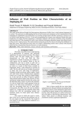
  • 1. Pratik Tiwari et al Int. Journal of Engineering Research and Applications www.ijera.com ISSN : 2248-9622, Vol. 4, Issue 3( Version 6), March 2014, pp.58-66 www.ijera.com 58 | P a g e Influence of Wall Position on Flow Characteristics of an Impinging Jet Pratik Tiwari, P. Mahathi, N. R. Choudhury and Vinayak Malhotra* (Department of Aerospace Engineering, SRM University, Kancheepuram District, Tamil Nadu, INDIA) ABSTRACT The study intends physical insight into heterogeneous phenomena of efflux from a small opening impinging on a surface. The work aims at understanding the role of wall location and orientation on flow characteristics of an impinging jet. Experiments were performed on an existing cascade tunnel with flow ejected at a velocity of 37 m/s from a small opening of (30 cm × 9 cm) and corresponding flow features were analyzed. Results show that outside the core region, the flow experiences a monotonic reduction with increase in distance along streamline and radial direction. The orientation of wall is more efficient in bringing substantial change when placed closer to the exit (low velocity losses). The wall orientation primarily governs the chances of strong flow deflection or back flow losses. Wall placed far away from exit results in diminishing returns with a critical value beyond which the flow characteristics become insensitive of wall orientation. Keywords - Efflux, shear interaction, vortices, wall jets, wall orientation, wall location. I. INTRODUCTION The study of jet efflux from a small opening is a phenomenon of practical and functional significance for space research activities. The subject involves mass and heat transfer and is widely characterized as: Free and Wall Jet. This classification is based on presence of a surface (i.e. wall) against the jet expelled. While in free jet configuration, jets exit a nozzle or tube into a stationary or moving fluid (same or different), wall jet refers to a stream of fluid blown normally or tangentially along a wall (subjected to position of wall). The free and wall jets are broadly encountered in nature and cover wide range of applications. Examples include aircraft gas turbine engines, liquid and solid rocket motors, boundary-layer separation control over a wing, film cooling on turbine blades, etc. In the wall jets, an efflux of liquid or gaseous when released against surface large amounts of mass and thermal energy transfers between the surface and the fluid takes place. Figure 1(a) shows the schematic of a free jet issued from a small opening. In free jet mode as the fluid moves downstream, it interacts with the surrounding fluid and its speed drops. Consequently, the efflux of jet rifts into two distinct regions viz., a region near the centerline where fluid interacts less with the surrounding medium and maintains nearly its initial speed some distance downstream. This region in which the speed is nearly that of the exit is termed as the potential core or the core region (see fig. 1(a) & (b)). The length of core region in jets under different conditions is a prominent factor. (a) (b) Figure 1: (a) Schematic of a free jet (b) Pictorial view of a free jet. Next is region outside the core where fluid comprehensively interacts with the surrounding fluid. This region is known as the entrainment region and it is identified by drastic change in flow characteristics (see Fig. 1(b)). The presence of a surface in front of a jet is very likely to alter the flow characteristics. This surface when placed at different locations and orientations will have significant implications. RESEARCH ARTICLE OPEN ACCESS
  • 2. Pratik Tiwari et al Int. Journal of Engineering Research and Applications www.ijera.com ISSN : 2248-9622, Vol. 4, Issue 3( Version 6), March 2014, pp.58-66 www.ijera.com 59 | P a g e Following the classical work of Glauert (1956) highlighting the flow due to a jet spreading out over a plane surface. In the last five decades research works have contributed significantly to the advancement in understanding of the free jets. The contributions have been reported in several reviews like Gardon and Akfirat (1966), Kercher and Tabakoff (1970), Sparrow and Alhomoud (1984), Gau and Chung (1991), Gori and Bossi (2000). The works provide an excellent review on the developments up to the end of the century. In the last decade appreciable advancements have occurred. Roy and Patel (2003) studied the dominant fluid-thermal characteristics of a pair of rectangular air jets impinging on an inclined surface. Heat transfer modes and flow characteristics were studied with eight different Reynolds numbers ranging from 500 to 20000. Aldabbagha and Mohamadb (2009) carried out a three-dimensional numerical study to determine the flow and heat transfer characteristics of impinging laminar array of square jets on a moving surface. They stated that a rather complex flow field with horseshoe vortices formed around the first column of jets due to the cross flow created by the moving surface. The velocity ratio of the moving plate increases the cross flow as a result a ground vortex cannot form in front of the second and third column jets compared with the case of fix surface. In recently, Azam et al., (2013) studied pressure distributions and oil flow on the plate to figure out the flow structures for the rectangular nozzles by comparing three-dimensional calculations to the experiments. They investigated at three different aspect ratio under-expanded impinging jet issued from rectangular nozzle. The results stated that the flow is separated on the impinging plate from center point toward outside and that the flow on the plate avoids the high-pressure areas. San and Chen (2014) explored the effects of jet-to-jet spacing and jet height on heat transfer characteristics of an impinging jet array. Tiwari et al., (2014) carried out experiments to investigate the effect of wall location on flow characteristics of an impinging jet and the core region. The work showed that increase in centerline wall location enhances the velocity losses. Wall location near to exit causes strong deflection of flow resulting formation of vortices with prominent chances of back flow. Furthermore, for a fixed wall location, increase in radial distance enhances the velocity losses, but it results in diminishing returns beyond a critical value. Although much has been done but complexity of the problem has prevented a complete understanding due to interaction between flow, heat and mass transfer. Therefore, a systematic study is needed to understand mechanisms controlling the behavior of jets and their flow characteristics. In the light of above-mentioned works, the work primarily focuses on flow characteristics of an impinging jet against varying wall location and orientation. This aspect of jets is yet to be comprehensively explored. Hence, a systematic study is needed to understand mechanisms controlling the behavior of jets when impinging on a wall placed at different locations and orientations besides the one open to atmosphere or without any wall. The interest in this class of problems is specifically driven by the need to have better understanding of fluid and thermal characteristics of jets. To address the above mentioned issue, the present work 1. Experimentally explores the effects of surface location and orientation on flow characteristics of an impinging jet. 2. Analyzes the role of key controlling parameters. II. EXPERIMENTAL SETUP AND SOLUTION METHODOLOGY A simple apparatus (Fig. 2(a)) was adapted for this study. The apparatus consisted of a) cascade tunnel (Fig. 2(b) base made of mild steel b) a Pitot tube (Fig. 2(a)) and c) Micro Manometer (Fig. 2(c)). The cascade tunnel issues a free air jet using a centrifugal blower with a velocity of 37 m/s. The efflux is from a small rectangular opening (dimensions 30 cm × 9 cm (Fig. 2(d)) into the air in a quiescent room. The flow characteristics are determined by establishing the pressure balance between dynamic pressure and the hydrostatic pressure. (a) (b) (c) Figure 2: Pictorial view of (a) complete experimental setup (b) side view of cascade tunnel (c) micro manometer.
  • 3. Pratik Tiwari et al Int. Journal of Engineering Research and Applications www.ijera.com ISSN : 2248-9622, Vol. 4, Issue 3( Version 6), March 2014, pp.58-66 www.ijera.com 60 | P a g e The dynamic pressure is measured using Pitot tube (exposed directly to the flow and stagnates it at surface measuring total pressure, the static holes are at the center and side of the tube measuring static pressure and the dynamic pressure is difference of the two pressures). The micro manometer calculates the hydrostatic pressure due to change in elevation of the fluid used (here distilled water) owing to different dynamic pressures under different conditions. The micro manometer exhibits an accuracy level of 0.001 cm height of the fluid and can measure the differential pressure up till the range of 300 mm of the used fluid. The dynamic pressure is equated to the hydrostatic pressure and the flow velocity (kinetic energy) is measured. It is important to note that all the readings were taken systematically in proper time interval and all the reading taken here represent the repeatability of results obtained. The wall used in the study is a rectangular cardboard surface with dimensions of 180 cm × 120 cm × 1 cm. The flow is turbulent and the effect was noted in fluctuations in the reading, so for every reading taken here the average repeated value with was accounted. The flow velocity is obtained by equating the dynamic head to pressure head obtained by the liquid height change as: 21 ( ) (1) 2 a l 1 oV g h h   From equation (1), the flow velocity “V” is determined as: 2 ( ) (2)l 1 o a V g h h     Where a Density of air (Kg/m3 ) l Density of water (Kg/m3 ) V Flow velocity (m/s) g Gravitational acceleration (m/s2 ) 0h Reading corresponding to zero differtial pressure 1 0h h Liquid head corresponding to the dynamic head Wϴ Wall orientation D Equivalent diameter of a circular exit (1D =18.54 cm) It is important to note that the density of liquid (here distilled water) depends on the place of use of the manometer (the atmospheric pressure and temperature at the time and place of use). While, the density of air can be calculated using the state relations for air for corresponding pressure and temperature. III. RESULTS A parametric experimental study was carried out to study the flow characteristics of a jet issued from a small opening and impinging on a wall placed normal at different locations and orientations. The effect was investigated by placing the wall placed at three different locations viz. far away from exit (18D & 15D), at an intermediate distance (10D) and at locations very close to exit (2D and 5D) and further varying orientation of wall in capacity of horizontal, vertical, 30o , 45o , 60o against the efflux. Here, „D‟ normalizes the streamline distance and all the readings were taken in folds of „D‟. It must be noted that „D‟ represents the equivalent diameter of a circular exit when compared to the exit of cascade tunnel (rectangular). First, the results obtained from the experimental setup were validated with the benchmark subject of flow characteristics of a free jet. Figure 3 shows the variation of normalized centerline velocity as a function of normalized streamline distance for a free jet. The exit velocities at different locations are normalized by maximum velocity (here, 37 m/s) and the streamline distance is normalized by the equivalent circular diameter „D‟. Results show that the flow characteristics exhibit a monotonically reducing behavior with increment in streamline distance. Figure 3: Variation of normalized centerline velocity as a function of normalized streamline distance for a free jet. Looking at the plot one can note that the as the jet exits the tunnel, there is drastic loss of flow velocity (kinetic energy) with increase in streamline distance. The core region is seen to extend till 3 units. Alongside the axial variation of a free jet, the variation of flow velocity in radial direction at various orientations (at differential of 5 mm) is investigated. Centreline distance (x/D) Vx/Vcmax. 0 2 4 6 8 10 12 14 16 18 0 0.2 0.4 0.6 0.8 1 Vx Centreline distance (x/D) Vx/Vcmax. 0 2 4 6 8 10 12 14 16 18 0 0.2 0.4 0.6 0.8 1 Vcmax.
  • 4. Pratik Tiwari et al Int. Journal of Engineering Research and Applications www.ijera.com ISSN : 2248-9622, Vol. 4, Issue 3( Version 6), March 2014, pp.58-66 www.ijera.com 61 | P a g e Figure 4: Variation of normalized radial velocity as a function of radial distance for a free jet. Figure 4 shows the variation of normalized velocity with distance in radial direction at axial locations of 2D, 5D, 10D and 18D respectively. Interestingly, a trend similar to variation in axial direction is observed in radial direction as well. As expected, the flow velocity reduces with increase in radial distance subjected to width of core region (here noted as 3 cm). Looking at the profiles it was noticed that, when the reading is taken very close to exit (here 2D), the flow lies in core region and with increase in distance suddenly comes out of it and velocity falls drastically. When the same trend was introspected at 5D, the maximum velocity (here at centerline) was found lower than at 2D. However a sudden drop in radial velocity was noted beyond some distance as the flow moves out of core region. While, at an intermediate distance of 10D, the flow is already out of core regime and is in entrainment region thus an overall sudden drop in flow velocity is seen. Furthermore, as the distance in radial direction increases, unlike wall placed closer to exit, here flow velocity reports a gradual drop. Similarly, at location far away from exit (here 18D), the trend of maximum velocity being lower with axial distance is followed alongside the gradual drop in flow velocity with increase in radial distance. The reason for above mentioned changes in axial and radial direction can be attributed to the shear interaction with surroundings leading to strong energy conversions. The length and width of core region dictates the velocity loss at different positions. Since from the results obtained it is evident that the experimental setup predicts correct results as preceding theories substantiates, the study was extended to investigate the effect of presence of a wall at different axial locations and orientations on flow characteristics. First the wall was placed in centerline against the flow at three different locations viz., very near to exit (5D), at an intermediate distance (10D), at a location far away from the exit (18D) in capacity of horizontal, vertical, 30o , 60o , 90o orientations respectively. Figure 5 shows variation of normalized centerline velocity as a function of wall location and orientation in comparison to maximum velocity. One can note that, when the wall is located far from exit (see Fig. 5(a)) with increment in orientation the velocity reduces. The centerline velocity at 18D is seen lower than maximum indicating the loss of kinetic energy. (a) (b) 0 5 10 15 20 25 0 0.2 0.4 0.6 0.8 1 x = 5D 0 5 10 15 20 25 0 0.2 0.4 0.6 0.8 1 x = 2D 0 5 10 15 20 25 0 0.2 0.4 0.6 0.8 1 x = 10D 0 5 10 15 20 25 0 0.2 0.4 0.6 0.8 1 x = 15D Radial distance (cm) Vy /Vcmax. 0 5 10 15 20 25 0 0.2 0.4 0.6 0.8 1 Vcmax. 0 2 4 6 8 10 12 14 0.4 0.6 0.8 1 W = 45o 0 2 4 6 8 10 12 14 0.4 0.6 0.8 1 W = 60 o 0 2 4 6 8 10 12 14 0.4 0.6 0.8 1 W= 90 o Wall = 18D Centreline distance (x/D) Vx /Vcmax. 0 2 4 6 8 10 12 14 0.4 0.5 0.6 0.7 0.8 0.9 1 W = 0 o 0 2 4 6 8 10 12 14 0.4 0.6 0.8 1 Vcmax. 0 2 4 6 8 10 12 14 0.4 0.6 0.8 1 W = 30o 0 1 2 3 4 5 6 0.6 0.7 0.8 0.9 1 W= 0o 0 1 2 3 4 5 6 0.6 0.7 0.8 0.9 1 W= 30o 0 1 2 3 4 5 6 0.6 0.7 0.8 0.9 1 W = 45o 0 1 2 3 4 5 6 0.6 0.7 0.8 0.9 1 W = 60o 0 1 2 3 4 5 6 0.6 0.7 0.8 0.9 1 W = 90 o 0 1 2 3 4 5 6 0.6 0.7 0.8 0.9 1 Centreline distance (x/D) Vx /Vcmax. 0 1 2 3 4 5 6 0.6 0.7 0.8 0.9 1 Vcmax. Wall = 10D
  • 5. Pratik Tiwari et al Int. Journal of Engineering Research and Applications www.ijera.com ISSN : 2248-9622, Vol. 4, Issue 3( Version 6), March 2014, pp.58-66 www.ijera.com 62 | P a g e (c) Figure 5: Variation of normalized centerline velocity as a function of wall orientation for wall located at (a) 18D (b) 10D (c) 5D. This loss of flow velocity is more when the wall is placed in vertical orientation however when kept horizontal or closer (here till 30o ) the effect more or less is same. This dictates that up to a fixed wall orientation the effect of shear interaction is within a closer range but as wall orientation changes beyond to vertical, it behaves as a case of free jet and significant losses are noted. Increased wall orientation increases the induced loss in flow velocity. Interestingly, at certain centerline distance the velocity profiles converges to corroborate the loss. For present case, till centerline distance of 3 units, the flow velocity loss is lower for all profiles indicating the presence of core region. Following the core region, further increment results sharp drop in velocity profiles. In this work, we refer to the point up-till which the core region exist in streamline direction as “VRM-PPT point” (Here 3 units= ~ 55 cm). A trend almost similar to far located wall (18D) is noted at a location of 10D. Beyond “VRM-PPT point” sharp drop in flow velocities is noted. The flow profiles are seen merging at centerline distance of 4 units. However, in this case when wall is placed parallel or is in vertical orientation to the flow the loss is lower than wall orientation in the range of (0- 30o ). For wall located at 10D the applicability of the flow can be more when wall is close to or vertically oriented. For the case when wall is located closer to exit (5D), the study was extended only for two orientations viz., horizontal and 30o . Expectedly, the centerline velocity is more and the flow is mainly confided in the core region. A crossover in flow velocity profiles is noted at a streamline distance of 1.5 cm. Here, the results strongly pronounce that when wall is located far away and orientated in range of horizontal, the tangential component of flow velocity can be effectively used for engineering applications. However, when placed closer flow gets deflected, there are strong chances of flow getting back so safety needs to be ensured especially in cases such as liquid and solid rocket motors where exhaust comes out at very high velocity. This engineering aspect can be widely used in applications ranging from heating, cooling to engineering where preceding designs are not sufficient. To understand the results in Figure 5, we next explore the effect of varying wall location for fixed orientations on centerline velocity. Figure 6 shows variation of normalized centerline velocity as a function of streamline distance for varying wall location and fixed orientation. (a) (b) 0 1 2 3 4 0.9 0.92 0.94 0.96 0.98 1 W = 0 o 0 1 2 3 4 0.9 0.92 0.94 0.96 0.98 1 W = 30o Centreline distance (x/D) Vx /Vcmax. 0 1 2 3 4 0.9 0.92 0.94 0.96 0.98 1 Vcmax. Wall = 5D 0 2 4 6 8 10 12 14 0.3 0.4 0.5 0.6 0.7 0.8 0.9 1 Wall = 18D 0 2 4 6 8 10 12 14 0.3 0.4 0.5 0.6 0.7 0.8 0.9 1 Wall = 5D 0 2 4 6 8 10 12 14 0.3 0.4 0.5 0.6 0.7 0.8 0.9 1 Wall = 10D Centreline distance (x/D) Vx /Vcmax. 0 2 4 6 8 10 12 14 0.3 0.4 0.5 0.6 0.7 0.8 0.9 1 Vcmax. Horizontal orientation 0 2 4 6 8 10 12 14 0.4 0.5 0.6 0.7 0.8 0.9 1 Wall = 10D 0 2 4 6 8 10 12 14 0.4 0.6 0.8 1 Wall = 5D 0 2 4 6 8 10 12 14 0.4 0.6 0.8 1 Wall = 18D Wall orientation = 30 o Centreline distance (x/D) Vx /Vcmax. 0 2 4 6 8 10 12 14 0.4 0.6 0.8 1 Vcmax.
  • 6. Pratik Tiwari et al Int. Journal of Engineering Research and Applications www.ijera.com ISSN : 2248-9622, Vol. 4, Issue 3( Version 6), March 2014, pp.58-66 www.ijera.com 63 | P a g e (c) (d) (e) Figure 6: Variation of normalized centreline velocity as a function of wall location at different orientations (a) Horizontal (b) 30o (c) 45o (d) 60o (e) Vertical All the profiles are in comparison to maximum centerline velocity. One can note that, for all fixed orientations as location of wall increases the loss in flow velocity increases. One can note that the wall placed closer to exit have more centerline velocity than the one placed far away. However, beyond “VRM-PPT point” all profiles fall drastically. When placed closer, the losses are low but when wall is placed far away the losses increases significantly. It is interesting to note that the flow velocity profiles for wall locations of 10D and 18D are close to each other and that loss of velocity at 18D is significantly lesser than at 10D till wall orientation is 30o. However, beyond orientation of 45o the profiles are seen to merge with each other. All profiles are seen to merge at centerline distance of 14 Units. For vertical orientation of wall, the loss in flow velocity is less for 10D as compared to 18D. The reason for this can be attributed to the shear interaction of flow as it starts expanding. The vortices formation when wall is placed at an orientation increases the flow losses. (a) (b) 0 2 4 6 8 10 12 14 0.4 0.5 0.6 0.7 0.8 0.9 1 Wall = 10D 0 2 4 6 8 10 12 14 0.4 0.6 0.8 1 Wall = 18D Centreline distance (x/D) Vx /Vcmax. 0 2 4 6 8 10 12 14 0.4 0.6 0.8 1 Vcmax. Wall orientation = 45 o 0 2 4 6 8 10 12 14 0.4 0.5 0.6 0.7 0.8 0.9 1 Wall = 18D 0 2 4 6 8 10 12 14 0.4 0.5 0.6 0.7 0.8 0.9 1 Wall = 10D Centreline distance (x/D) Vx /Vcmax. 0 2 4 6 8 10 12 14 0.4 0.5 0.6 0.7 0.8 0.9 1 Vcmax. Wall orientation = 60 o 0 2 4 6 8 10 12 14 0.4 0.5 0.6 0.7 0.8 0.9 1 Wall = 18D 0 2 4 6 8 10 12 14 0.4 0.5 0.6 0.7 0.8 0.9 1 Wall = 10D Wall orientation = Vertical Vx /Vcmax. 0 2 4 6 8 10 12 14 0.4 0.5 0.6 0.7 0.8 0.9 1 Vcmax. 0 2 4 6 8 10 12 14 16 18 20 0 0.2 0.4 0.6 0.8 1 W = 0o 0 2 4 6 8 10 12 14 16 18 20 0 0.2 0.4 0.6 0.8 1 W = 30o 0 2 4 6 8 10 12 14 16 18 20 0 0.2 0.4 0.6 0.8 1 W = 45o 0 2 4 6 8 10 12 14 16 18 20 0 0.2 0.4 0.6 0.8 1 W = 60 o 0 2 4 6 8 10 12 14 16 18 20 0 0.2 0.4 0.6 0.8 1 W = 90 o Wall = 18D Radial distance (cm) Vy /Vcmax. 0 2 4 6 8 10 12 14 16 18 20 0 0.2 0.4 0.6 0.8 1 Vcmax. 0 2 4 6 8 10 12 14 16 18 20 0 0.2 0.4 0.6 0.8 1 W = 0 o 0 2 4 6 8 10 12 14 16 18 20 0 0.2 0.4 0.6 0.8 1 W = 30 o 0 2 4 6 8 10 12 14 16 18 20 0 0.2 0.4 0.6 0.8 1 W = 45 o 0 2 4 6 8 10 12 14 16 18 20 0 0.2 0.4 0.6 0.8 1 W = 60 o 0 2 4 6 8 10 12 14 16 18 20 0 0.2 0.4 0.6 0.8 1 W = 90 o Radial distance (cm) Vy /Vcmax. 0 2 4 6 8 10 12 14 16 18 20 0 0.2 0.4 0.6 0.8 1 Vcmax. Wall = 10D
  • 7. Pratik Tiwari et al Int. Journal of Engineering Research and Applications www.ijera.com ISSN : 2248-9622, Vol. 4, Issue 3( Version 6), March 2014, pp.58-66 www.ijera.com 64 | P a g e (c) Figure 7: Variation of normalized radial velocity at orientation of 4D as a function of streamline wall orientation (a) 18D (b) 10D (c) 5D. Next, the effect of wall orientation on radial component of flow velocity is explored. The wall was placed at axial locations of 5D, 10D and 18D. Figure 7 shows variation of normalized radial component of velocity as a function of radial distance for varying wall location and orientations. The effect in radial direction is catapulted to a distance of 20 cm at axial orientation of 4D for all the profiles. Looking at the profiles, one can note that beyond radial distance of 3 cm, the velocity profiles for different wall orientations exhibits drastic drop in kinetic energy similar to the centreline variation. As expected, the rate of reduction in flow velocity is more when wall is placed far away (here 10D and 18D). For all the profiles, a gradual drop till “VRM-PPT” and then sharp drop is noted. It is interesting to note that when wall is placed far away, the loss at a fixed location is more when placed horizontal. However, as the location of wall reduces, the loss due to horizontal orientation is found minimum. Wall locations of 18D and 10D almost follows same trend showing insensitiveness beyond a critical value. Almost similar trend is observed at wall locations of 30o . Beyond a certain orientation (here 30o ) the losses are insignificant to the wall orientation as most of the profiles looks similar and follows same trend. In the last part, the wall locations were kept fixed and orientations were varied and effect on radial component was investigated. Furthermore, to het a holistic understanding, next we fix the wall orientation and analyze the effect of wall location on flow energy. Figure 8 shows variation of normalized radial velocity as a function of radial distance for varying wall location and fixed orientation. All velocity profiles are determined at axial location of 4D. As seen in Fig.7, beyond an orientation of 30o the significant change in velocity profiles is not noted. Wall when placed at 18D at different orientations shows that, at an orientation of 30o maximum reduction in velocity is noted followed by horizontal. One can also note that wall when placed at 45o , 60o , 90o almost follows similar profiles. The velocity profiles were also compared for vertical and horizontal orientations and it was observed that the loss in velocity with horizontal orientation is less than vertical. Furthermore at a radial distance of 14 cm and above profiles are seen merging. The velocity profiles for 10D and 18D were found to merge with each other indicating that beyond a certain distance the velocity change is insensitive to wall orientation. At a faraway distance of 13 mm all the velocity profiles are seen converging to a common value indicating a peculiar point of identical velocity loss. (a) (b) 0 2 4 6 8 10 12 14 16 18 20 0 0.2 0.4 0.6 0.8 1 W = 30o 0 2 4 6 8 10 12 14 16 18 20 0 0.2 0.4 0.6 0.8 1 W = 0 o Radial distance (cm) Vy /Vcmax. 0 2 4 6 8 10 12 14 16 18 20 0 0.2 0.4 0.6 0.8 1 Vcmax. Wall = 5D 0 2 4 6 8 10 12 14 16 18 20 0 0.2 0.4 0.6 0.8 1 Wall = 10D 0 2 4 6 8 10 12 14 16 18 20 0 0.2 0.4 0.6 0.8 1 Wall = 5D 0 2 4 6 8 10 12 14 16 18 20 0 0.2 0.4 0.6 0.8 1 Wall = 18D Radial distance (cm) Vy /Vcmax. 0 2 4 6 8 10 12 14 16 18 20 0 0.2 0.4 0.6 0.8 1 Vcmax. Wall orientation = 0 o 0 2 4 6 8 10 12 14 16 18 20 0 0.2 0.4 0.6 0.8 1 Wall = 10D Wall orientation = 30o 0 2 4 6 8 10 12 14 16 18 20 0 0.2 0.4 0.6 0.8 1 Wall = 5D 0 2 4 6 8 10 12 14 16 18 20 0 0.2 0.4 0.6 0.8 1 Wall = 18D Radial distance (cm) Vy /Vcmax. 0 2 4 6 8 10 12 14 16 18 20 0 0.2 0.4 0.6 0.8 1 Vcmax.
  • 8. Pratik Tiwari et al Int. Journal of Engineering Research and Applications www.ijera.com ISSN : 2248-9622, Vol. 4, Issue 3( Version 6), March 2014, pp.58-66 www.ijera.com 65 | P a g e (c) (d) (e) Figure 8: Variation of normalized radial velocity at radial location of 4D as a function of streamline wall location at different orientations (a) Horizontal (b) 30o (c) 45o (d) 60o (e) Vertical IV. CONCLUSIONS An experimental exploration was carried out to understand the effects of wall orientation on flow characteristics of a free jet. The results predicted by existing experimental setup were validated with benchmark preceding free jet theory and extended further to note the implications of wall orientation. Based on results obtained following conclusions may be drawn from this study: The increase in wall orientation axially, enhances the velocity losses beyond a critical distance (i.e., core region). The orientation of wall near to exit results in low velocity losses and consequently strong deflection of flow resulting formation of vortices with more chances of back flow. For a fixed wall orientation, increase in radial distance enhances the velocity losses, but it results in diminishing returns beyond a critical value indicating insensitiveness of wall orientation after a certain distance. REFERENCES [1] M. B. Glauert., “The wall jet,” Journal of Fluid Mechanics, vol. 1, pp. 625–643, 1956. [2] Gardon. R., Akfirat J. C., “Heat transfer characteristics of impinging two dimensional air jets,” Int. J. Heat Mass Transfer, 88, 101-108, 1966. [3] Kercher. D. M., Tabakoff, W., “Heat Transfer by a Square Array of Round Air Jets Impinging Perpendicular to a Flat Surface Including the Effect of Spent Air,” J. Eng. Power, 92, 73-82, 1970. [4] Martin H., “Heat and mass transfer between impinging gas jets and solid surfaces,” Adv. in Heat Transfer, 13, 1-60, 1977. [5] Sparrow, E.M., Alhomoud, A., “Impingement heat transfer at a circular cylinder due to an offset or non offset slot jet,” Int. J. Heat Mass Transfer, 27, 2297- 2307, 1984. [6] Gau, C., Chung, C.M., “Surface curvature effect on slot-air-jet impingement cooling flow and heat transfer process,” Journal of Heat Transfer, 113, 858-864, 1991. [7] Gori, F., Bossi, L., “On the cooling effect of an air jet along the surface of a cylinder,” Int. Communications in Heat and Mass Transfer, 27, 667-676, 2000. [8] Roy, S., Patel, P., “Study of heat transfer for a pair of rectangular jets impinging on an inclined surface,” Int. J. Heat Mass Transfer, 46, 411-425, 2003. [9] Aldabbagha, L.B.Y., Mohamadb, A.A., “A three-dimensional numerical simulation of impinging jet arrays on a moving plate,” Int. J. Heat Mass Transfer, 52, 4894 -4900, 2009. 0 2 4 6 8 10 12 14 16 18 20 0 0.2 0.4 0.6 0.8 1 Wall = 10D 0 2 4 6 8 10 12 14 16 18 20 0 0.2 0.4 0.6 0.8 1 Wall = 18D Radial distance (cm) Vy /Vcmax. 0 2 4 6 8 10 12 14 16 18 20 0 0.2 0.4 0.6 0.8 1 Vcmax. Wall orientation = 45o 0 2 4 6 8 10 12 14 16 18 20 0 0.2 0.4 0.6 0.8 1 Wall = 18D 0 2 4 6 8 10 12 14 16 18 20 0 0.2 0.4 0.6 0.8 1 Wall = 10D Radial distance (cm) Vy /Vcmax. 0 2 4 6 8 10 12 14 16 18 20 0 0.2 0.4 0.6 0.8 1 Vcmax. Wall orientation = 60 o 0 2 4 6 8 10 12 14 16 18 20 0 0.2 0.4 0.6 0.8 1 Wall = 18D(90o ) 0 2 4 6 8 10 12 14 16 18 20 0 0.2 0.4 0.6 0.8 1 Wall = 18D(0 o ) 0 2 4 6 8 10 12 14 16 18 20 0 0.2 0.4 0.6 0.8 1 Wall = 10D(90 o ) 0 2 4 6 8 10 12 14 16 18 20 0 0.2 0.4 0.6 0.8 1 Wall = 10D(0 o ) 0 2 4 6 8 10 12 14 16 18 20 0 0.2 0.4 0.6 0.8 1 Wall = 5D(0o ) Radial distance (cm) Vy /Vcmax. 0 2 4 6 8 10 12 14 16 18 20 0 0.2 0.4 0.6 0.8 1 Vcmax.
  • 9. Pratik Tiwari et al Int. Journal of Engineering Research and Applications www.ijera.com ISSN : 2248-9622, Vol. 4, Issue 3( Version 6), March 2014, pp.58-66 www.ijera.com 66 | P a g e [10] Azam, R., Ozono, H., Yaga, M., Teruya, I., Ishikawac, M., “Study on Under expanded Impinging Jet Issued from Rectangular Nozzle,”5th BSME International Conference on Thermal Engineering, 56, 269-274, 2013. [11] San, Jung-Yang., Chen, Jenq-Jye., “Effects of jet-to-jet spacing and jet height on heat transfer characteristics of an impinging jet array,” Int. J. Heat Mass Transfer, 71, 8- 17, 2014. [12] Tiwari, Pratik., Mahathi, P., Choudhury, N.R., Malhotra, V., “Effects of wall orientation on flow characteristics of an impinging jet,” Proc. Int. conference on recent trends in engineering and technology, Cochin, Kerala, January 18-19, 2014.