SlideShare une entreprise Scribd logo
1  sur  4
Télécharger pour lire hors ligne
International Research Journal of Engineering and Technology (IRJET) e-ISSN: 2395 -0056
Volume: 04 Issue: 03 | Mar -2017 www.irjet.net p-ISSN: 2395-0072
© 2017, IRJET | Impact Factor value: 5.181 | ISO 9001:2008 Certified Journal | Page 1246
Regeneration in Variable Frequency Drives and Energy saving Methods
Rasin K R1, Arunkumar G2
1MTech in Power Electronics and Drives, VIT University, Vellore, Tamilnadu,India
2Professor, SELECT school, VIT university,Vellore,Tamilnadu, India
---------------------------------------------------------------------***---------------------------------------------------------------------
Abstract - When an induction motor is driven by a variable
frequency drive, electric power delivered from the supply is
regenerated back while the motor decelerates by applying
negative torque to the motor shaft. Energy storage capacity
inside the variable frequency drives is usually high limited so
energy regenerated should be return back to the grid instead
of dissipating as heat .This paper reviews different supply line
regeneration options for effective utilization of regenerated
power of variable frequency induction motor Drives and a
comparison of this methods.
Key Words: Variable frequency Drives, Regeneration,
Matrix converter, SPWM, Utility cost saving,
Regeneration power unit selection.
1. INTRODUCTION
Some applications demands operation in a quadrant region
where applied torque is in the opposite direction of rotation of
Induction motor. The variable frequency Drive must be drive
release stored energy from the mechanicalloadsystemthrough
the motor terminals to the inverter. This situation faces when
the variable frequency drive is trying to break the rotating
induction motor, such asthemotorinertiastartsdeceleratingor
a situation of whenever using loading as in a dynamometer, or
when an overhauling holding back . As the Load fed back stored
energy to the front end, the main DC bus capacitors of the drive
starts charging. The lack of a proper method of utilizing that
energy, will leads to continue rise of DC bus voltage to
dangerous Level and the drive will get tripped on a fault of Bus
over voltage. A method called line Regenerationdischargesthat
energy from the DC bus capacitors and feed it back on the AC
utility. The Regenerative power can be dissipated using an
arrangement of Brake chopper and Braking Resistor there by
the drive will be protected from overvoltage tripping. Also an
overvoltage control enabling is available in variable frequency
Drives. A significant energy cost saving can be achieved by a
regenerative power unit especially in frequent on and off
applications, deceleration along with large inertia load, and
torque is in overhauling condition. Such applications include
decanter centrifuges, hoists, spindle drives, cranes, elevators
etc., because of this electricity cost per kilowatt hour is more
expensive. So it will be beneficialtounderstandaboutthebasics
of regenerative units and to review estimated energy cost
saving. Three types of regenerativepowerunitsareavailable
depends on the applications. Basic features and power
topologies are explained and compared. Dynamic brake
chopper and resistor arrangement is used to convert
regenerated power in to heat loss becauseoflowinstallation
cost and simplicity.
1.1 Regenerative converter
In most of the Drives applications Braking choppers and
resistors are used to simply dissipate the power in the form
of heat loss. An efficient low budget alternative solution
called line regeneration using Regenerative converters that
can replace the use of the dynamic braking chopping circuit
and external brake resistor network. During regeneration
excess regenerative energy available in the inverter front
end of variable frequency Drive bypass it to the ac power
source through a converter circuit. Figure 1 illustrates how
the excessive regenerative energy will feedback from an
induction motor to the supply side by utilizing a
regenerative converter circuit parallel to the drive inverter
circuit , . During motoring mode, the Variable frequency
Drives transfer power to the motor terminals without
coming the regenerative converter in the picture of main
power flow. So during motoring there is no loss in the
regenerative converter .When the regenerationtaking place,
the dc link capacitors starts charging. Regenerative
converter will get activated because of regenerative energy
International Research Journal of Engineering and Technology (IRJET) e-ISSN: 2395 -0056
Volume: 04 Issue: 03 | Mar -2017 www.irjet.net p-ISSN: 2395-0072
© 2017, IRJET | Impact Factor value: 5.181 | ISO 9001:2008 Certified Journal | Page 1247
charges dc link capacitors of the variable frequency drives.
The regenerative converter converts the Dc voltage in to AC
and returns stored energy in the dc capacitors to the grid.
Size of Variable Frequency Drives will vary according to the
power ratings thereby the size of regenerative converters
will vary according to drive size, Regenerative Power and
Duty Ratio. The 6-step PWM method is used for switching
thereby can reduce the switching losses in very low value.
Some applications demands very high duty cycle braking, in
such situations the regenerative converter can reduce the
cost of electricity usage by significantly improving the
system efficiency.
1.2 Sinusoidal PWM converter
In both motoring andregenerativepowerconditions a highly
efficient solution developed to regulate dc bus voltagecalled
sinusoidal PWM converter. The converter is designed to
generate sinusoidal current waveform at supply mains side
grid side with very low rate of harmonic distortion,
approximately saying total harmonic distortion (THD) will
be 5%.The converter is designed to obey the standard of
IEEE-519 .To make possible the synchronization with input
grid voltage control of input current also taking place,which
will help to obtain a unity input power factor. Thesinusoidal
PWM converter is connected in series between the Variable
frequency Drive and incoming power line. To reduce the
harmonic from the grid side an AC filter is accompanied in
front end of the grid side, usually a LCL filter is used as an
external harmonic filter component to reduce input ac
current harmonics. For controlling the inverter mostly
sinusoidal PWM techniques is used because of it is possible
to control the output voltage and frequency accordingly
with sine functions Sinusoidal pulse width modulation is
widely used in control applications. Because of circuit is less
complex and simple control scheme. SPWM techniques are
characterized by same amplitude pulses with different duty
cycles for each period. The width of these pulses are
controlled to obtain inverter output voltage modulationand
to minimize its harmonic content there by reducing THD.
1.3 Matrix Converter
A matrix converter is a single stage conversion converter
with direct ac to ac conversion having motoring and
regeneration capability. With the helps of bidirectional
controlled switches direct conversion of power from AC to
AC.The converter is characterized bysinusoidal waveforms
that decides the output and input switchingfrequencies.By
using bidirectional switches it is possible to control power
factor input. In addition, the main advantage is lack of DC
voltage link will provide compact design. The matrix
converter using to control induction motors has more
advantages over traditional rectifier-invertertypeVariable
Speed converters. The Input and output waveforms of
Matrix converter issinusoidal,withminimizedhigherorder
harmonics components, there is no subharmonics will
present. Matrix converters has energy flow capability in
both directions. Input power factor can be fullycontrolled. .
It has minimal energy storage Requirements, Which will
improve the lifespan of energy storing capacitors.
The disadvantages of Matrix converters are transfer ratio of
its maximum input output voltage limited to nearly 85 % for
sinusoidal output and input waveforms. Comparing to
conventional frequency converters matrix converters
requires more number of semiconductor devices which will
increase the switching stresses. Discrete unidirectional
devices are variously arranged to be used for each bi-
directional switch because no monolithic bi directional
switches exist .It is sensitive to the fluctuations of the input
voltage systemIn matrix converters using nine bidirectional
switches alternating input is directly transformed into
variable frequency ac output. So sinusoidal regeneration
converter and Variable frequency Drives functions are
combined. This combination enables the induction motors’
to operate in regenerating and motoring modes without
using an additionalDrive.Traditional rectifier-invertercircuit
requires more maintenance because there is diode rectifier
and dc electrolytic capacitor in the main power flow as a
filter circuit. Normally, an electrolytic capacitor is bulky in
size also has a shorter lifetime thanotherparts.Butinmatrix
converters there is electrolytic capacitor present so needs
less maintenance. It is possible to control Input current in
matrix converters this capability reduce harmonics of input
current significantly. Under full load condition inputcurrent
harmonic THD is in the range of 5% - 10%.Unliketraditional
frequency converters external line reactor circuit is not
required to minimize current harmonics, which are usually
bulky in size.
2. ENERGY SAVING USING REGENRATION
CONVERTERS
For an application requires to feedback excess regenerative
energy to the supply grid, line regeneration is an option.
Regeneration happens when the load tries to rotate the
motor shaft faster thantheoutputfrequencyinverteroutput.
This is usually called to as “overhauling”, and may occur
when trying to reduce speed a load, or applying mechanical
power to the motor system by something on the loading. In
International Research Journal of Engineering and Technology (IRJET) e-ISSN: 2395 -0056
Volume: 04 Issue: 03 | Mar -2017 www.irjet.net p-ISSN: 2395-0072
© 2017, IRJET | Impact Factor value: 5.181 | ISO 9001:2008 Certified Journal | Page 1248
these conditions, the inverter is behaves to restrain the
motion of the load by inertia and this leads to regeneration.
Here a converter is used to sends excess regenerativepower
back to the grid by line regeneration technique. To
accomplish this, the drive system must utilizea regenerative
converter. This converterconnectedintothecommondc link
just like the existing drives. This converter receives excess
feedback energy caused dc voltage from the DC bus and
produce a six-step waveform back to the grid.By using
matrix converter power factor is always kept nearly at 0.95.
Because the power factor is constant or regardless of
operation frequency, energy wastage is minimized.
Regeneration results in to rise of DC bus voltage, will cause
to tripping of variable frequency Drive because of DC bus
overvoltage .The traditional method of resolvingthisissueis
by using Brake chopper circuit and external resistors the
regenerative power is dissipated as heat loss. A dc bus
voltage sensing circuit is accompanied with chopper
transistor which will sense the increase in dc voltage and
which will enable the transistor and will conduct and
dissipate the power in external resistorconnected.Instead of
simply wasting the energy as heat loss we can convert to
efficient form and utilize in grid side. The Regeneration
Converters replacestraditional dynamic brakingsystem, and
transform this regenerated powerback intosupplysidegrid.
It converts that regenerated energy back into the grid as
three-phase AC supply instead of wasting it as heat loss. By
doing so the regenerated power can be feedback to input,
and minimizes the energy consumption and therefore the
utility bill. In other words regenerative converter unit is like
another generator placed on the utility grid, supplying
power into it by synchronizing to it.
2.1 Estimation of Energy Savings
The Regeneration converter unit converts the excess
regenerated power in grid under the same condition of
power is dissipated as heat. So that calculating total energy
saving using a regenerationconverterissametocalculating
the heat loss taking place in braking resistor. For the above
required braking duty cycle and braking torque must be
determined. From the obtained data, we can calculate total
amount of regenerated energy for a given period. The
Regenerative converter converts almost 95% of
regenerated energy in to grid. This gives all the variables
needed to calculate the kW-hr reclaimed for give time
period. By knowing the utility demand rate, this reading
values can be converted into money and hence a payback
period.
2.2 Comparison of Regeneration Converters.
In variable frequencydrives underregenerativeconditionall
three above said converters has good energy saving
capability. Instead of wasting the regenerated power simply
as heat loss in external resistor circuit. The converter circuit
said in first section multiple VFD connection is but lowinput
current harmonics is present and medium level installation
space is required. The best low-cost solution is sinusoidal
PWM converter which has utility good utility cost saving
using Regenerative braking and multiple VFD connection is
possible similar to first converter. The best solution may
differ if extra benefits such as low current harmonics and
unity power factor are alsoimportant,Thematrixconverters
is another fair solution which require less space comparing
to other two regeneration converter units and multiple VFD
connection is not possible and matrix converter is a product
that has both regeneration converter and VFD capabilities
inherently. The table compares regeneration power units.
Table -1:
Item Regenerati
ve
converter
SPWM
converter
Matrix
convert
er
Utility cost saving
by regenerative
braking
Good Good Good
Low input current
harmonics
None Good Good
Multiple VFD
connection
Yes Yes No
Initial cost
including VFD
Good Fair Good
Input power factor
improvement
None Good Good
Installation space
including VFD
Medium Large Small
3. CONCLUSIONS
There is huge amount of energy is wasting in variable
frequency drives when a regeneration take place, By using
brake chopper and external resistor arrangement the
excessive regenerative power is simply wasted as
heatloss.Itcan be found that from energy saving calculation
almost 50% of energy is wasted as simply heatloss.By using
Regenerative converters this excessive regenerative power
can be feedback to the grid. For multiple VFD connections
the converters explained in first and second section is good
choice but in overall performance matrix converter is more
efficient choice.
International Research Journal of Engineering and Technology (IRJET) e-ISSN: 2395 -0056
Volume: 04 Issue: 03 | Mar -2017 www.irjet.net p-ISSN: 2395-0072
© 2017, IRJET | Impact Factor value: 5.181 | ISO 9001:2008 Certified Journal | Page 1249
REFERENCES
[1] D. H. Braun;T. P. Gilmore;W. A.Maslowski“Regenerative
converter for PWM AC drives”, IEEE Transactions on
Industry Applications, Volume: 30, Year: 1994, , Issue: 5
,Pages: 1176 - 1184, DOI: 10.1109/28.315227
[2] Patrick. W. Wheeler, J. Rodriguez, Jon. C. Clare, L.
Empringham, "Matrix converter-A TechnologyReview",
IEEE Trans. Ind. Electron, vol. 49, no. 2, pp. 276-288,Apr.
2002.
[3] Norm Lindner, “Line regenerating with variable speed
AC drives”.

Contenu connexe

Tendances

Optimization Technique for Power Quality Improvement using DSTATCOM Neural Ne...
Optimization Technique for Power Quality Improvement using DSTATCOM Neural Ne...Optimization Technique for Power Quality Improvement using DSTATCOM Neural Ne...
Optimization Technique for Power Quality Improvement using DSTATCOM Neural Ne...
ijtsrd
 
A Voltage Controlled Dstatcom for Power Quality Improvement
A Voltage Controlled Dstatcom for Power Quality ImprovementA Voltage Controlled Dstatcom for Power Quality Improvement
A Voltage Controlled Dstatcom for Power Quality Improvement
iosrjce
 
IRENA_The Role of Grid Codes v2
IRENA_The Role of Grid Codes v2IRENA_The Role of Grid Codes v2
IRENA_The Role of Grid Codes v2
fboshell
 
Analysis and Implementation of Artificial Neural Network Techniques for Power...
Analysis and Implementation of Artificial Neural Network Techniques for Power...Analysis and Implementation of Artificial Neural Network Techniques for Power...
Analysis and Implementation of Artificial Neural Network Techniques for Power...
ijtsrd
 

Tendances (20)

12 16134 paper 064 ijeecs(edit)
12 16134 paper 064 ijeecs(edit)12 16134 paper 064 ijeecs(edit)
12 16134 paper 064 ijeecs(edit)
 
IRJET - Review Paper on RSC-MLC Base Smart PV-DSTATCOM for Multi Objective Pu...
IRJET - Review Paper on RSC-MLC Base Smart PV-DSTATCOM for Multi Objective Pu...IRJET - Review Paper on RSC-MLC Base Smart PV-DSTATCOM for Multi Objective Pu...
IRJET - Review Paper on RSC-MLC Base Smart PV-DSTATCOM for Multi Objective Pu...
 
Minimizing losses in power distribution system
Minimizing losses in power distribution systemMinimizing losses in power distribution system
Minimizing losses in power distribution system
 
Implementation Of Advanced Control Strategy For High-Frequency Single-Switch ...
Implementation Of Advanced Control Strategy For High-Frequency Single-Switch ...Implementation Of Advanced Control Strategy For High-Frequency Single-Switch ...
Implementation Of Advanced Control Strategy For High-Frequency Single-Switch ...
 
An adaptive power oscillation damping controller by statcom with energy storage
An adaptive power oscillation damping controller by statcom with energy storageAn adaptive power oscillation damping controller by statcom with energy storage
An adaptive power oscillation damping controller by statcom with energy storage
 
IRJET- 127 Multilevel Inverter
IRJET- 127 Multilevel InverterIRJET- 127 Multilevel Inverter
IRJET- 127 Multilevel Inverter
 
Optimization Technique for Power Quality Improvement using DSTATCOM Neural Ne...
Optimization Technique for Power Quality Improvement using DSTATCOM Neural Ne...Optimization Technique for Power Quality Improvement using DSTATCOM Neural Ne...
Optimization Technique for Power Quality Improvement using DSTATCOM Neural Ne...
 
International Journal of Engineering Research and Development (IJERD)
International Journal of Engineering Research and Development (IJERD)International Journal of Engineering Research and Development (IJERD)
International Journal of Engineering Research and Development (IJERD)
 
Analysis of Power Factor Improvement Techniques in case of Non Linear System ...
Analysis of Power Factor Improvement Techniques in case of Non Linear System ...Analysis of Power Factor Improvement Techniques in case of Non Linear System ...
Analysis of Power Factor Improvement Techniques in case of Non Linear System ...
 
IRJET- A Comparative Study of Control Algorithms for DSTATCOM for Harmonic El...
IRJET- A Comparative Study of Control Algorithms for DSTATCOM for Harmonic El...IRJET- A Comparative Study of Control Algorithms for DSTATCOM for Harmonic El...
IRJET- A Comparative Study of Control Algorithms for DSTATCOM for Harmonic El...
 
ISLANDING DETECTION TECHNIQUE FOR DISTRIBUTED GENERATION SYSTEM
ISLANDING DETECTION TECHNIQUE FOR DISTRIBUTED GENERATION SYSTEMISLANDING DETECTION TECHNIQUE FOR DISTRIBUTED GENERATION SYSTEM
ISLANDING DETECTION TECHNIQUE FOR DISTRIBUTED GENERATION SYSTEM
 
A Voltage Controlled Dstatcom for Power Quality Improvement
A Voltage Controlled Dstatcom for Power Quality ImprovementA Voltage Controlled Dstatcom for Power Quality Improvement
A Voltage Controlled Dstatcom for Power Quality Improvement
 
IRJET- Methods for Improved Efficiency in DC-DC Buck Converter
IRJET-  	  Methods for Improved Efficiency in DC-DC Buck ConverterIRJET-  	  Methods for Improved Efficiency in DC-DC Buck Converter
IRJET- Methods for Improved Efficiency in DC-DC Buck Converter
 
IRENA_The Role of Grid Codes v2
IRENA_The Role of Grid Codes v2IRENA_The Role of Grid Codes v2
IRENA_The Role of Grid Codes v2
 
Analysis and Implementation of Artificial Neural Network Techniques for Power...
Analysis and Implementation of Artificial Neural Network Techniques for Power...Analysis and Implementation of Artificial Neural Network Techniques for Power...
Analysis and Implementation of Artificial Neural Network Techniques for Power...
 
IRJET- Technologies Compensating Reactive Power :A Review
IRJET- Technologies Compensating Reactive Power :A ReviewIRJET- Technologies Compensating Reactive Power :A Review
IRJET- Technologies Compensating Reactive Power :A Review
 
Bo36390397
Bo36390397Bo36390397
Bo36390397
 
Power factor correction of 6.6 kv distribution line in lc11 rmhs department, ...
Power factor correction of 6.6 kv distribution line in lc11 rmhs department, ...Power factor correction of 6.6 kv distribution line in lc11 rmhs department, ...
Power factor correction of 6.6 kv distribution line in lc11 rmhs department, ...
 
Dc25617623
Dc25617623Dc25617623
Dc25617623
 
Segan
SeganSegan
Segan
 

Similaire à Regeneration in Variable Frequency Drives and Energy Saving Methods

Snubberless current fed half bridge isolated converter for fuel cell applicat...
Snubberless current fed half bridge isolated converter for fuel cell applicat...Snubberless current fed half bridge isolated converter for fuel cell applicat...
Snubberless current fed half bridge isolated converter for fuel cell applicat...
IAEME Publication
 

Similaire à Regeneration in Variable Frequency Drives and Energy Saving Methods (20)

IRJET- A Review on - PMBLDC Motor Drive with Power Factor Correction Controller
IRJET- A Review on - PMBLDC Motor Drive with Power Factor Correction ControllerIRJET- A Review on - PMBLDC Motor Drive with Power Factor Correction Controller
IRJET- A Review on - PMBLDC Motor Drive with Power Factor Correction Controller
 
SAYEED AHMED_VIF
SAYEED AHMED_VIFSAYEED AHMED_VIF
SAYEED AHMED_VIF
 
Study on power control of doubly fed induction generator
Study on power control of doubly fed induction generatorStudy on power control of doubly fed induction generator
Study on power control of doubly fed induction generator
 
Power Quality Analysis Using Active NPC Multilevel inverter in PV sourced sta...
Power Quality Analysis Using Active NPC Multilevel inverter in PV sourced sta...Power Quality Analysis Using Active NPC Multilevel inverter in PV sourced sta...
Power Quality Analysis Using Active NPC Multilevel inverter in PV sourced sta...
 
Power Quality Analysis Using Active NPC Multilevel inverter in PV sourced sta...
Power Quality Analysis Using Active NPC Multilevel inverter in PV sourced sta...Power Quality Analysis Using Active NPC Multilevel inverter in PV sourced sta...
Power Quality Analysis Using Active NPC Multilevel inverter in PV sourced sta...
 
Snubberless current fed half bridge isolated converter for fuel cell applicat...
Snubberless current fed half bridge isolated converter for fuel cell applicat...Snubberless current fed half bridge isolated converter for fuel cell applicat...
Snubberless current fed half bridge isolated converter for fuel cell applicat...
 
Grid Connected Wind Turbine Generator with Real and Reactive Power Control
Grid Connected Wind Turbine Generator with Real and Reactive Power ControlGrid Connected Wind Turbine Generator with Real and Reactive Power Control
Grid Connected Wind Turbine Generator with Real and Reactive Power Control
 
Modeling and Simulation for Transformer Ratio Controlled Slip Power Recovery ...
Modeling and Simulation for Transformer Ratio Controlled Slip Power Recovery ...Modeling and Simulation for Transformer Ratio Controlled Slip Power Recovery ...
Modeling and Simulation for Transformer Ratio Controlled Slip Power Recovery ...
 
A DC-DC Converter with Ripple Current Cancellation Based On Duty Cycle Selection
A DC-DC Converter with Ripple Current Cancellation Based On Duty Cycle SelectionA DC-DC Converter with Ripple Current Cancellation Based On Duty Cycle Selection
A DC-DC Converter with Ripple Current Cancellation Based On Duty Cycle Selection
 
Real Coded Genetic Algorithm Based Improvement of Efficiency in Interleaved B...
Real Coded Genetic Algorithm Based Improvement of Efficiency in Interleaved B...Real Coded Genetic Algorithm Based Improvement of Efficiency in Interleaved B...
Real Coded Genetic Algorithm Based Improvement of Efficiency in Interleaved B...
 
IRJET- Variable Frequency Drive Used in Treadmill
IRJET- Variable Frequency Drive Used in TreadmillIRJET- Variable Frequency Drive Used in Treadmill
IRJET- Variable Frequency Drive Used in Treadmill
 
Dual Bridge Rectifier for PMSG Variable Speed Wind Energy Conversion Systems
Dual Bridge Rectifier for PMSG Variable Speed Wind Energy Conversion SystemsDual Bridge Rectifier for PMSG Variable Speed Wind Energy Conversion Systems
Dual Bridge Rectifier for PMSG Variable Speed Wind Energy Conversion Systems
 
IRJET- Modified Cascaded H - Bridge Multilevel Inverter for Household Appliances
IRJET- Modified Cascaded H - Bridge Multilevel Inverter for Household AppliancesIRJET- Modified Cascaded H - Bridge Multilevel Inverter for Household Appliances
IRJET- Modified Cascaded H - Bridge Multilevel Inverter for Household Appliances
 
Analysis of Fuel Cell Based Multilevel DC-DC Boost Converter for Induction Motor
Analysis of Fuel Cell Based Multilevel DC-DC Boost Converter for Induction MotorAnalysis of Fuel Cell Based Multilevel DC-DC Boost Converter for Induction Motor
Analysis of Fuel Cell Based Multilevel DC-DC Boost Converter for Induction Motor
 
Power Quality Analysis of Vienna Rectifier for BLDC Motor Drive Application
Power Quality Analysis of Vienna Rectifier for BLDC Motor Drive ApplicationPower Quality Analysis of Vienna Rectifier for BLDC Motor Drive Application
Power Quality Analysis of Vienna Rectifier for BLDC Motor Drive Application
 
Hardware Implementation of Single Phase Power Factor Correction System using ...
Hardware Implementation of Single Phase Power Factor Correction System using ...Hardware Implementation of Single Phase Power Factor Correction System using ...
Hardware Implementation of Single Phase Power Factor Correction System using ...
 
IRJET- Hybrid Feed Forward Control for Power Factor Correction Rectifier
IRJET-  	  Hybrid Feed Forward Control for Power Factor Correction RectifierIRJET-  	  Hybrid Feed Forward Control for Power Factor Correction Rectifier
IRJET- Hybrid Feed Forward Control for Power Factor Correction Rectifier
 
Switched Inductor based Quadratic Following Boost Converter
Switched Inductor based Quadratic Following Boost ConverterSwitched Inductor based Quadratic Following Boost Converter
Switched Inductor based Quadratic Following Boost Converter
 
IRJET- Dynamic Voltage Restorer Frame Work to Improve Power Quality of the Di...
IRJET- Dynamic Voltage Restorer Frame Work to Improve Power Quality of the Di...IRJET- Dynamic Voltage Restorer Frame Work to Improve Power Quality of the Di...
IRJET- Dynamic Voltage Restorer Frame Work to Improve Power Quality of the Di...
 
IRJET- Designing of Single Ended Primary Inductance Converter for Solar P...
IRJET-  	  Designing of Single Ended Primary Inductance Converter for Solar P...IRJET-  	  Designing of Single Ended Primary Inductance Converter for Solar P...
IRJET- Designing of Single Ended Primary Inductance Converter for Solar P...
 

Plus de IRJET Journal

Plus de IRJET Journal (20)

TUNNELING IN HIMALAYAS WITH NATM METHOD: A SPECIAL REFERENCES TO SUNGAL TUNNE...
TUNNELING IN HIMALAYAS WITH NATM METHOD: A SPECIAL REFERENCES TO SUNGAL TUNNE...TUNNELING IN HIMALAYAS WITH NATM METHOD: A SPECIAL REFERENCES TO SUNGAL TUNNE...
TUNNELING IN HIMALAYAS WITH NATM METHOD: A SPECIAL REFERENCES TO SUNGAL TUNNE...
 
STUDY THE EFFECT OF RESPONSE REDUCTION FACTOR ON RC FRAMED STRUCTURE
STUDY THE EFFECT OF RESPONSE REDUCTION FACTOR ON RC FRAMED STRUCTURESTUDY THE EFFECT OF RESPONSE REDUCTION FACTOR ON RC FRAMED STRUCTURE
STUDY THE EFFECT OF RESPONSE REDUCTION FACTOR ON RC FRAMED STRUCTURE
 
A COMPARATIVE ANALYSIS OF RCC ELEMENT OF SLAB WITH STARK STEEL (HYSD STEEL) A...
A COMPARATIVE ANALYSIS OF RCC ELEMENT OF SLAB WITH STARK STEEL (HYSD STEEL) A...A COMPARATIVE ANALYSIS OF RCC ELEMENT OF SLAB WITH STARK STEEL (HYSD STEEL) A...
A COMPARATIVE ANALYSIS OF RCC ELEMENT OF SLAB WITH STARK STEEL (HYSD STEEL) A...
 
Effect of Camber and Angles of Attack on Airfoil Characteristics
Effect of Camber and Angles of Attack on Airfoil CharacteristicsEffect of Camber and Angles of Attack on Airfoil Characteristics
Effect of Camber and Angles of Attack on Airfoil Characteristics
 
A Review on the Progress and Challenges of Aluminum-Based Metal Matrix Compos...
A Review on the Progress and Challenges of Aluminum-Based Metal Matrix Compos...A Review on the Progress and Challenges of Aluminum-Based Metal Matrix Compos...
A Review on the Progress and Challenges of Aluminum-Based Metal Matrix Compos...
 
Dynamic Urban Transit Optimization: A Graph Neural Network Approach for Real-...
Dynamic Urban Transit Optimization: A Graph Neural Network Approach for Real-...Dynamic Urban Transit Optimization: A Graph Neural Network Approach for Real-...
Dynamic Urban Transit Optimization: A Graph Neural Network Approach for Real-...
 
Structural Analysis and Design of Multi-Storey Symmetric and Asymmetric Shape...
Structural Analysis and Design of Multi-Storey Symmetric and Asymmetric Shape...Structural Analysis and Design of Multi-Storey Symmetric and Asymmetric Shape...
Structural Analysis and Design of Multi-Storey Symmetric and Asymmetric Shape...
 
A Review of “Seismic Response of RC Structures Having Plan and Vertical Irreg...
A Review of “Seismic Response of RC Structures Having Plan and Vertical Irreg...A Review of “Seismic Response of RC Structures Having Plan and Vertical Irreg...
A Review of “Seismic Response of RC Structures Having Plan and Vertical Irreg...
 
A REVIEW ON MACHINE LEARNING IN ADAS
A REVIEW ON MACHINE LEARNING IN ADASA REVIEW ON MACHINE LEARNING IN ADAS
A REVIEW ON MACHINE LEARNING IN ADAS
 
Long Term Trend Analysis of Precipitation and Temperature for Asosa district,...
Long Term Trend Analysis of Precipitation and Temperature for Asosa district,...Long Term Trend Analysis of Precipitation and Temperature for Asosa district,...
Long Term Trend Analysis of Precipitation and Temperature for Asosa district,...
 
P.E.B. Framed Structure Design and Analysis Using STAAD Pro
P.E.B. Framed Structure Design and Analysis Using STAAD ProP.E.B. Framed Structure Design and Analysis Using STAAD Pro
P.E.B. Framed Structure Design and Analysis Using STAAD Pro
 
A Review on Innovative Fiber Integration for Enhanced Reinforcement of Concre...
A Review on Innovative Fiber Integration for Enhanced Reinforcement of Concre...A Review on Innovative Fiber Integration for Enhanced Reinforcement of Concre...
A Review on Innovative Fiber Integration for Enhanced Reinforcement of Concre...
 
Survey Paper on Cloud-Based Secured Healthcare System
Survey Paper on Cloud-Based Secured Healthcare SystemSurvey Paper on Cloud-Based Secured Healthcare System
Survey Paper on Cloud-Based Secured Healthcare System
 
Review on studies and research on widening of existing concrete bridges
Review on studies and research on widening of existing concrete bridgesReview on studies and research on widening of existing concrete bridges
Review on studies and research on widening of existing concrete bridges
 
React based fullstack edtech web application
React based fullstack edtech web applicationReact based fullstack edtech web application
React based fullstack edtech web application
 
A Comprehensive Review of Integrating IoT and Blockchain Technologies in the ...
A Comprehensive Review of Integrating IoT and Blockchain Technologies in the ...A Comprehensive Review of Integrating IoT and Blockchain Technologies in the ...
A Comprehensive Review of Integrating IoT and Blockchain Technologies in the ...
 
A REVIEW ON THE PERFORMANCE OF COCONUT FIBRE REINFORCED CONCRETE.
A REVIEW ON THE PERFORMANCE OF COCONUT FIBRE REINFORCED CONCRETE.A REVIEW ON THE PERFORMANCE OF COCONUT FIBRE REINFORCED CONCRETE.
A REVIEW ON THE PERFORMANCE OF COCONUT FIBRE REINFORCED CONCRETE.
 
Optimizing Business Management Process Workflows: The Dynamic Influence of Mi...
Optimizing Business Management Process Workflows: The Dynamic Influence of Mi...Optimizing Business Management Process Workflows: The Dynamic Influence of Mi...
Optimizing Business Management Process Workflows: The Dynamic Influence of Mi...
 
Multistoried and Multi Bay Steel Building Frame by using Seismic Design
Multistoried and Multi Bay Steel Building Frame by using Seismic DesignMultistoried and Multi Bay Steel Building Frame by using Seismic Design
Multistoried and Multi Bay Steel Building Frame by using Seismic Design
 
Cost Optimization of Construction Using Plastic Waste as a Sustainable Constr...
Cost Optimization of Construction Using Plastic Waste as a Sustainable Constr...Cost Optimization of Construction Using Plastic Waste as a Sustainable Constr...
Cost Optimization of Construction Using Plastic Waste as a Sustainable Constr...
 

Dernier

Call Now ≽ 9953056974 ≼🔝 Call Girls In New Ashok Nagar ≼🔝 Delhi door step de...
Call Now ≽ 9953056974 ≼🔝 Call Girls In New Ashok Nagar  ≼🔝 Delhi door step de...Call Now ≽ 9953056974 ≼🔝 Call Girls In New Ashok Nagar  ≼🔝 Delhi door step de...
Call Now ≽ 9953056974 ≼🔝 Call Girls In New Ashok Nagar ≼🔝 Delhi door step de...
9953056974 Low Rate Call Girls In Saket, Delhi NCR
 
result management system report for college project
result management system report for college projectresult management system report for college project
result management system report for college project
Tonystark477637
 
Call for Papers - Educational Administration: Theory and Practice, E-ISSN: 21...
Call for Papers - Educational Administration: Theory and Practice, E-ISSN: 21...Call for Papers - Educational Administration: Theory and Practice, E-ISSN: 21...
Call for Papers - Educational Administration: Theory and Practice, E-ISSN: 21...
Christo Ananth
 
AKTU Computer Networks notes --- Unit 3.pdf
AKTU Computer Networks notes ---  Unit 3.pdfAKTU Computer Networks notes ---  Unit 3.pdf
AKTU Computer Networks notes --- Unit 3.pdf
ankushspencer015
 

Dernier (20)

data_management_and _data_science_cheat_sheet.pdf
data_management_and _data_science_cheat_sheet.pdfdata_management_and _data_science_cheat_sheet.pdf
data_management_and _data_science_cheat_sheet.pdf
 
Vivazz, Mieres Social Housing Design Spain
Vivazz, Mieres Social Housing Design SpainVivazz, Mieres Social Housing Design Spain
Vivazz, Mieres Social Housing Design Spain
 
Booking open Available Pune Call Girls Koregaon Park 6297143586 Call Hot Ind...
Booking open Available Pune Call Girls Koregaon Park  6297143586 Call Hot Ind...Booking open Available Pune Call Girls Koregaon Park  6297143586 Call Hot Ind...
Booking open Available Pune Call Girls Koregaon Park 6297143586 Call Hot Ind...
 
Call Now ≽ 9953056974 ≼🔝 Call Girls In New Ashok Nagar ≼🔝 Delhi door step de...
Call Now ≽ 9953056974 ≼🔝 Call Girls In New Ashok Nagar  ≼🔝 Delhi door step de...Call Now ≽ 9953056974 ≼🔝 Call Girls In New Ashok Nagar  ≼🔝 Delhi door step de...
Call Now ≽ 9953056974 ≼🔝 Call Girls In New Ashok Nagar ≼🔝 Delhi door step de...
 
The Most Attractive Pune Call Girls Manchar 8250192130 Will You Miss This Cha...
The Most Attractive Pune Call Girls Manchar 8250192130 Will You Miss This Cha...The Most Attractive Pune Call Girls Manchar 8250192130 Will You Miss This Cha...
The Most Attractive Pune Call Girls Manchar 8250192130 Will You Miss This Cha...
 
Thermal Engineering -unit - III & IV.ppt
Thermal Engineering -unit - III & IV.pptThermal Engineering -unit - III & IV.ppt
Thermal Engineering -unit - III & IV.ppt
 
KubeKraft presentation @CloudNativeHooghly
KubeKraft presentation @CloudNativeHooghlyKubeKraft presentation @CloudNativeHooghly
KubeKraft presentation @CloudNativeHooghly
 
UNIT - IV - Air Compressors and its Performance
UNIT - IV - Air Compressors and its PerformanceUNIT - IV - Air Compressors and its Performance
UNIT - IV - Air Compressors and its Performance
 
result management system report for college project
result management system report for college projectresult management system report for college project
result management system report for college project
 
Extrusion Processes and Their Limitations
Extrusion Processes and Their LimitationsExtrusion Processes and Their Limitations
Extrusion Processes and Their Limitations
 
The Most Attractive Pune Call Girls Budhwar Peth 8250192130 Will You Miss Thi...
The Most Attractive Pune Call Girls Budhwar Peth 8250192130 Will You Miss Thi...The Most Attractive Pune Call Girls Budhwar Peth 8250192130 Will You Miss Thi...
The Most Attractive Pune Call Girls Budhwar Peth 8250192130 Will You Miss Thi...
 
Thermal Engineering-R & A / C - unit - V
Thermal Engineering-R & A / C - unit - VThermal Engineering-R & A / C - unit - V
Thermal Engineering-R & A / C - unit - V
 
Unit 1 - Soil Classification and Compaction.pdf
Unit 1 - Soil Classification and Compaction.pdfUnit 1 - Soil Classification and Compaction.pdf
Unit 1 - Soil Classification and Compaction.pdf
 
(INDIRA) Call Girl Bhosari Call Now 8617697112 Bhosari Escorts 24x7
(INDIRA) Call Girl Bhosari Call Now 8617697112 Bhosari Escorts 24x7(INDIRA) Call Girl Bhosari Call Now 8617697112 Bhosari Escorts 24x7
(INDIRA) Call Girl Bhosari Call Now 8617697112 Bhosari Escorts 24x7
 
Call for Papers - Educational Administration: Theory and Practice, E-ISSN: 21...
Call for Papers - Educational Administration: Theory and Practice, E-ISSN: 21...Call for Papers - Educational Administration: Theory and Practice, E-ISSN: 21...
Call for Papers - Educational Administration: Theory and Practice, E-ISSN: 21...
 
University management System project report..pdf
University management System project report..pdfUniversity management System project report..pdf
University management System project report..pdf
 
Online banking management system project.pdf
Online banking management system project.pdfOnline banking management system project.pdf
Online banking management system project.pdf
 
Top Rated Pune Call Girls Budhwar Peth ⟟ 6297143586 ⟟ Call Me For Genuine Se...
Top Rated  Pune Call Girls Budhwar Peth ⟟ 6297143586 ⟟ Call Me For Genuine Se...Top Rated  Pune Call Girls Budhwar Peth ⟟ 6297143586 ⟟ Call Me For Genuine Se...
Top Rated Pune Call Girls Budhwar Peth ⟟ 6297143586 ⟟ Call Me For Genuine Se...
 
ONLINE FOOD ORDER SYSTEM PROJECT REPORT.pdf
ONLINE FOOD ORDER SYSTEM PROJECT REPORT.pdfONLINE FOOD ORDER SYSTEM PROJECT REPORT.pdf
ONLINE FOOD ORDER SYSTEM PROJECT REPORT.pdf
 
AKTU Computer Networks notes --- Unit 3.pdf
AKTU Computer Networks notes ---  Unit 3.pdfAKTU Computer Networks notes ---  Unit 3.pdf
AKTU Computer Networks notes --- Unit 3.pdf
 

Regeneration in Variable Frequency Drives and Energy Saving Methods

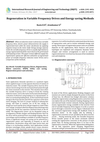
  • 1. International Research Journal of Engineering and Technology (IRJET) e-ISSN: 2395 -0056 Volume: 04 Issue: 03 | Mar -2017 www.irjet.net p-ISSN: 2395-0072 © 2017, IRJET | Impact Factor value: 5.181 | ISO 9001:2008 Certified Journal | Page 1246 Regeneration in Variable Frequency Drives and Energy saving Methods Rasin K R1, Arunkumar G2 1MTech in Power Electronics and Drives, VIT University, Vellore, Tamilnadu,India 2Professor, SELECT school, VIT university,Vellore,Tamilnadu, India ---------------------------------------------------------------------***--------------------------------------------------------------------- Abstract - When an induction motor is driven by a variable frequency drive, electric power delivered from the supply is regenerated back while the motor decelerates by applying negative torque to the motor shaft. Energy storage capacity inside the variable frequency drives is usually high limited so energy regenerated should be return back to the grid instead of dissipating as heat .This paper reviews different supply line regeneration options for effective utilization of regenerated power of variable frequency induction motor Drives and a comparison of this methods. Key Words: Variable frequency Drives, Regeneration, Matrix converter, SPWM, Utility cost saving, Regeneration power unit selection. 1. INTRODUCTION Some applications demands operation in a quadrant region where applied torque is in the opposite direction of rotation of Induction motor. The variable frequency Drive must be drive release stored energy from the mechanicalloadsystemthrough the motor terminals to the inverter. This situation faces when the variable frequency drive is trying to break the rotating induction motor, such asthemotorinertiastartsdeceleratingor a situation of whenever using loading as in a dynamometer, or when an overhauling holding back . As the Load fed back stored energy to the front end, the main DC bus capacitors of the drive starts charging. The lack of a proper method of utilizing that energy, will leads to continue rise of DC bus voltage to dangerous Level and the drive will get tripped on a fault of Bus over voltage. A method called line Regenerationdischargesthat energy from the DC bus capacitors and feed it back on the AC utility. The Regenerative power can be dissipated using an arrangement of Brake chopper and Braking Resistor there by the drive will be protected from overvoltage tripping. Also an overvoltage control enabling is available in variable frequency Drives. A significant energy cost saving can be achieved by a regenerative power unit especially in frequent on and off applications, deceleration along with large inertia load, and torque is in overhauling condition. Such applications include decanter centrifuges, hoists, spindle drives, cranes, elevators etc., because of this electricity cost per kilowatt hour is more expensive. So it will be beneficialtounderstandaboutthebasics of regenerative units and to review estimated energy cost saving. Three types of regenerativepowerunitsareavailable depends on the applications. Basic features and power topologies are explained and compared. Dynamic brake chopper and resistor arrangement is used to convert regenerated power in to heat loss becauseoflowinstallation cost and simplicity. 1.1 Regenerative converter In most of the Drives applications Braking choppers and resistors are used to simply dissipate the power in the form of heat loss. An efficient low budget alternative solution called line regeneration using Regenerative converters that can replace the use of the dynamic braking chopping circuit and external brake resistor network. During regeneration excess regenerative energy available in the inverter front end of variable frequency Drive bypass it to the ac power source through a converter circuit. Figure 1 illustrates how the excessive regenerative energy will feedback from an induction motor to the supply side by utilizing a regenerative converter circuit parallel to the drive inverter circuit , . During motoring mode, the Variable frequency Drives transfer power to the motor terminals without coming the regenerative converter in the picture of main power flow. So during motoring there is no loss in the regenerative converter .When the regenerationtaking place, the dc link capacitors starts charging. Regenerative converter will get activated because of regenerative energy
  • 2. International Research Journal of Engineering and Technology (IRJET) e-ISSN: 2395 -0056 Volume: 04 Issue: 03 | Mar -2017 www.irjet.net p-ISSN: 2395-0072 © 2017, IRJET | Impact Factor value: 5.181 | ISO 9001:2008 Certified Journal | Page 1247 charges dc link capacitors of the variable frequency drives. The regenerative converter converts the Dc voltage in to AC and returns stored energy in the dc capacitors to the grid. Size of Variable Frequency Drives will vary according to the power ratings thereby the size of regenerative converters will vary according to drive size, Regenerative Power and Duty Ratio. The 6-step PWM method is used for switching thereby can reduce the switching losses in very low value. Some applications demands very high duty cycle braking, in such situations the regenerative converter can reduce the cost of electricity usage by significantly improving the system efficiency. 1.2 Sinusoidal PWM converter In both motoring andregenerativepowerconditions a highly efficient solution developed to regulate dc bus voltagecalled sinusoidal PWM converter. The converter is designed to generate sinusoidal current waveform at supply mains side grid side with very low rate of harmonic distortion, approximately saying total harmonic distortion (THD) will be 5%.The converter is designed to obey the standard of IEEE-519 .To make possible the synchronization with input grid voltage control of input current also taking place,which will help to obtain a unity input power factor. Thesinusoidal PWM converter is connected in series between the Variable frequency Drive and incoming power line. To reduce the harmonic from the grid side an AC filter is accompanied in front end of the grid side, usually a LCL filter is used as an external harmonic filter component to reduce input ac current harmonics. For controlling the inverter mostly sinusoidal PWM techniques is used because of it is possible to control the output voltage and frequency accordingly with sine functions Sinusoidal pulse width modulation is widely used in control applications. Because of circuit is less complex and simple control scheme. SPWM techniques are characterized by same amplitude pulses with different duty cycles for each period. The width of these pulses are controlled to obtain inverter output voltage modulationand to minimize its harmonic content there by reducing THD. 1.3 Matrix Converter A matrix converter is a single stage conversion converter with direct ac to ac conversion having motoring and regeneration capability. With the helps of bidirectional controlled switches direct conversion of power from AC to AC.The converter is characterized bysinusoidal waveforms that decides the output and input switchingfrequencies.By using bidirectional switches it is possible to control power factor input. In addition, the main advantage is lack of DC voltage link will provide compact design. The matrix converter using to control induction motors has more advantages over traditional rectifier-invertertypeVariable Speed converters. The Input and output waveforms of Matrix converter issinusoidal,withminimizedhigherorder harmonics components, there is no subharmonics will present. Matrix converters has energy flow capability in both directions. Input power factor can be fullycontrolled. . It has minimal energy storage Requirements, Which will improve the lifespan of energy storing capacitors. The disadvantages of Matrix converters are transfer ratio of its maximum input output voltage limited to nearly 85 % for sinusoidal output and input waveforms. Comparing to conventional frequency converters matrix converters requires more number of semiconductor devices which will increase the switching stresses. Discrete unidirectional devices are variously arranged to be used for each bi- directional switch because no monolithic bi directional switches exist .It is sensitive to the fluctuations of the input voltage systemIn matrix converters using nine bidirectional switches alternating input is directly transformed into variable frequency ac output. So sinusoidal regeneration converter and Variable frequency Drives functions are combined. This combination enables the induction motors’ to operate in regenerating and motoring modes without using an additionalDrive.Traditional rectifier-invertercircuit requires more maintenance because there is diode rectifier and dc electrolytic capacitor in the main power flow as a filter circuit. Normally, an electrolytic capacitor is bulky in size also has a shorter lifetime thanotherparts.Butinmatrix converters there is electrolytic capacitor present so needs less maintenance. It is possible to control Input current in matrix converters this capability reduce harmonics of input current significantly. Under full load condition inputcurrent harmonic THD is in the range of 5% - 10%.Unliketraditional frequency converters external line reactor circuit is not required to minimize current harmonics, which are usually bulky in size. 2. ENERGY SAVING USING REGENRATION CONVERTERS For an application requires to feedback excess regenerative energy to the supply grid, line regeneration is an option. Regeneration happens when the load tries to rotate the motor shaft faster thantheoutputfrequencyinverteroutput. This is usually called to as “overhauling”, and may occur when trying to reduce speed a load, or applying mechanical power to the motor system by something on the loading. In
  • 3. International Research Journal of Engineering and Technology (IRJET) e-ISSN: 2395 -0056 Volume: 04 Issue: 03 | Mar -2017 www.irjet.net p-ISSN: 2395-0072 © 2017, IRJET | Impact Factor value: 5.181 | ISO 9001:2008 Certified Journal | Page 1248 these conditions, the inverter is behaves to restrain the motion of the load by inertia and this leads to regeneration. Here a converter is used to sends excess regenerativepower back to the grid by line regeneration technique. To accomplish this, the drive system must utilizea regenerative converter. This converterconnectedintothecommondc link just like the existing drives. This converter receives excess feedback energy caused dc voltage from the DC bus and produce a six-step waveform back to the grid.By using matrix converter power factor is always kept nearly at 0.95. Because the power factor is constant or regardless of operation frequency, energy wastage is minimized. Regeneration results in to rise of DC bus voltage, will cause to tripping of variable frequency Drive because of DC bus overvoltage .The traditional method of resolvingthisissueis by using Brake chopper circuit and external resistors the regenerative power is dissipated as heat loss. A dc bus voltage sensing circuit is accompanied with chopper transistor which will sense the increase in dc voltage and which will enable the transistor and will conduct and dissipate the power in external resistorconnected.Instead of simply wasting the energy as heat loss we can convert to efficient form and utilize in grid side. The Regeneration Converters replacestraditional dynamic brakingsystem, and transform this regenerated powerback intosupplysidegrid. It converts that regenerated energy back into the grid as three-phase AC supply instead of wasting it as heat loss. By doing so the regenerated power can be feedback to input, and minimizes the energy consumption and therefore the utility bill. In other words regenerative converter unit is like another generator placed on the utility grid, supplying power into it by synchronizing to it. 2.1 Estimation of Energy Savings The Regeneration converter unit converts the excess regenerated power in grid under the same condition of power is dissipated as heat. So that calculating total energy saving using a regenerationconverterissametocalculating the heat loss taking place in braking resistor. For the above required braking duty cycle and braking torque must be determined. From the obtained data, we can calculate total amount of regenerated energy for a given period. The Regenerative converter converts almost 95% of regenerated energy in to grid. This gives all the variables needed to calculate the kW-hr reclaimed for give time period. By knowing the utility demand rate, this reading values can be converted into money and hence a payback period. 2.2 Comparison of Regeneration Converters. In variable frequencydrives underregenerativeconditionall three above said converters has good energy saving capability. Instead of wasting the regenerated power simply as heat loss in external resistor circuit. The converter circuit said in first section multiple VFD connection is but lowinput current harmonics is present and medium level installation space is required. The best low-cost solution is sinusoidal PWM converter which has utility good utility cost saving using Regenerative braking and multiple VFD connection is possible similar to first converter. The best solution may differ if extra benefits such as low current harmonics and unity power factor are alsoimportant,Thematrixconverters is another fair solution which require less space comparing to other two regeneration converter units and multiple VFD connection is not possible and matrix converter is a product that has both regeneration converter and VFD capabilities inherently. The table compares regeneration power units. Table -1: Item Regenerati ve converter SPWM converter Matrix convert er Utility cost saving by regenerative braking Good Good Good Low input current harmonics None Good Good Multiple VFD connection Yes Yes No Initial cost including VFD Good Fair Good Input power factor improvement None Good Good Installation space including VFD Medium Large Small 3. CONCLUSIONS There is huge amount of energy is wasting in variable frequency drives when a regeneration take place, By using brake chopper and external resistor arrangement the excessive regenerative power is simply wasted as heatloss.Itcan be found that from energy saving calculation almost 50% of energy is wasted as simply heatloss.By using Regenerative converters this excessive regenerative power can be feedback to the grid. For multiple VFD connections the converters explained in first and second section is good choice but in overall performance matrix converter is more efficient choice.
  • 4. International Research Journal of Engineering and Technology (IRJET) e-ISSN: 2395 -0056 Volume: 04 Issue: 03 | Mar -2017 www.irjet.net p-ISSN: 2395-0072 © 2017, IRJET | Impact Factor value: 5.181 | ISO 9001:2008 Certified Journal | Page 1249 REFERENCES [1] D. H. Braun;T. P. Gilmore;W. A.Maslowski“Regenerative converter for PWM AC drives”, IEEE Transactions on Industry Applications, Volume: 30, Year: 1994, , Issue: 5 ,Pages: 1176 - 1184, DOI: 10.1109/28.315227 [2] Patrick. W. Wheeler, J. Rodriguez, Jon. C. Clare, L. Empringham, "Matrix converter-A TechnologyReview", IEEE Trans. Ind. Electron, vol. 49, no. 2, pp. 276-288,Apr. 2002. [3] Norm Lindner, “Line regenerating with variable speed AC drives”.