Steering Damper for Hydraulic Steering System using Smart Fluid
•
0 j'aime•8 vues

https://www.irjet.net/archives/V9/i9/IRJET-V9I9219.pdf

Recommandé
Recommandé
Contenu connexe
Similaire à Steering Damper for Hydraulic Steering System using Smart Fluid
Similaire à Steering Damper for Hydraulic Steering System using Smart Fluid (20)
Plus de IRJET Journal
Plus de IRJET Journal (20)
Dernier
Dernier (20)
Steering Damper for Hydraulic Steering System using Smart Fluid
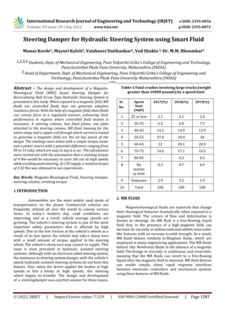
- 1. International Research Journal of Engineering and Technology (IRJET) e-ISSN: 2395-0056 p-ISSN: 2395-0072 Volume: 09 Issue: 09 | Sep 2022 www.irjet.net Steering Damper for Hydraulic Steering System using Smart Fluid Manas Korde1, Mayuri Kalvit2, Vaishnavi Daithankar3, Ved Shukla 4, Dr. M.M. Bhoomkar5 1,2,3,4 Students, Dept. of Mechanical Engineering, Pune Vidyarthi Griha’s College of Engineering and Technology, Pune,Savitribai Phule Pune University, Maharashtra (INDIA) 5 Head of Department, Dept. of Mechanical Engineering, Pune Vidyarthi Griha’s College of Engineering and Technology, Pune,Savitribai Phule Pune University Maharashtra (INDIA) ---------------------------------------------------------------------***--------------------------------------------------------------------- Abstract - The design and development of a Magneto- Rheological Fluid (MRF) based Steering Damper for Recirculating Ball Screw Type Hydraulic Steering System is presented in this study. When exposed to a magnetic field, MR fluids are controlled fluids that can generate adaptive resistance forces. With the help of a magnetic field, these fluids can convey force in a regulated manner, enhancing their performance in regions where controlled fluid motion is necessary. A steering column, two fixed plates, one plate attached to the steering column, MR fluid, housing for the entire setup, and a copper coil through which currentis routed to generate a magnetic field are the six key pieces of the design. The readings were taken with a simple torque meter and a power source with a potential difference ranging from 09 to 15 volts, which are easy to tap in a car. The calculations were carried out with the assumption that a resisting torque of 4 Nm would be necessary to steer the car at high speeds while avoiding understeering. At 15V supply, a resistivetorque of 3.92 Nm was obtained in our experiments. Key Words: Magneto-Rheological Fluid, Steering Damper, steering column, resisting torque 1.INTRODUCTION Automobiles are the most widely used mode of transportation on the planet. Commercial vehicles are frequently utilized all over the world to convey various items. In today's modern day, road conditions are improving, and as a result, vehicle average speeds are growing. The vehicle's steering system is one of the most important safety parameters that is affected by high speeds. Due to the low friction at the vehicle's wheels as a result of its fast speed, the vehicle may take a sharp turn with a small amount of torque applied to the steering wheel. The vehicle's sharp turn may causeit to topple. This issue is most prevalent in hydraulic assisted steering systems; although with an electronicaided steering system, the assistance to steering systemchanges with the vehicle's speed, hydraulic assisted steering systems do not have this feature. Also, when the driver applies the brakes at high speeds or hits a bump at high speeds, the steering wheel begins to tremble. The design and development of a steeringdamper was a perfect answer for these issues. Table-1 Fatal crashes involving large trucks (weight greater than 10000 pounds) by a speed limit Sr. No. Speed limit (mph) 2017(%) 2018(%) 2019(%) 1 25 or less 2.1 2.1 2.4 2 30-35 6.5 6.8 7.5 3 40-45 14.2 14.9 13.9 4 50-55 37.4 34.9 36 5 60-65 22 20.1 20.5 6 70-75 14.6 17.1 16.5 7 80-85 - 0.2 0.3 8 No statuto ry limit 0.3 0.7 0.9 9 Unknown 2.9 3.2 1.9 10 Total 100 100 100 2. MR FLUID Magnetorheological fluids are materials that change their rheological behavior dramatically when exposed to a magnetic field. The science of flow and deformation is known as rheology. An MR fluid is a free-flowing, liquid fluid that, in the presence of a high magnetic field, can increase its viscosity in millisecondsand exhibit semi-solid- like features with an increase in yield strength. As a result, MR fluids behave similarly to Bingham fluids, which are employed in many engineering applications. The MR fluids behave like Newtonian fluids in the absence of a magnetic field. Thechange in viscosity is continuous and reversible, meaning that the MR fluids can revert to a free-flowing liquid after the magnetic field is removed. MR fluid devices can enable simple, silent, rapid response interfaces between electronic controllers and mechanical systems using these features of MR fluids. © 2022, IRJET | Impact Factor value: 7.529 | ISO 9001:2008 Certified Journal | Page 1287
- 2. International Research Journal of Engineering and Technology (IRJET) e-ISSN: 2395-0056 p-ISSN: 2395-0072 Volume: 09 Issue: 09 | Sep 2022 www.irjet.net 2.1 WORKING OF MR FLUID TECHNOLOGY: In the presence of a magnetic field, the properties of the MR fluid can be controlled. The rheological properties of the MR fluid are comparable to those of the base fluid in the absence of a magnetic field, exceptthat it is slightly thicker due to the presence of metal particles. These metal particles align themselves along the flow direction in the absence of a magnetic field, but when a magnetic field is applied, each metal particle becomes a dipole and aligns itself along the magnetic field direction. As a result, a chain-like structure forms along the magnetic flux line, providingmechanical resistance to the flow and increasing fluidviscosity. The fluid gains yield strength as a result of the mechanical resistance provided by the chain column, making it stiff like a semi-solid. The yield strength is determined by the stiffness of the magneticfield as well as the quality and quantity of metal particles. The MR effect can be reversed. The fluid returns to its original state when the magnetic field is removed. The controlled features of MR fluids have been discovered to be useful in the application of the smart fluid idea. With the use of magnetism, the fluid velocity is controlled by adjusting its viscosity. The controllability and quick reaction of the rheological qualities make MR fluid technology a smart fluid withapplications where fluid motion is controlled by modifying the viscosity. 3. CURRENT STEERING SYSTEM The steering system is the vehicle's primary interfacewith the driver. The steering system has apparent challenges: accurate steering with no play is required. It should be direct and smooth, as well as small and light. It must also give the driver a perfect sense of theroad surface and assist the wheels in returning to a straight-ahead posture. At high speeds, the power steering gear truly comes into its own in terms of safety potential. Hydraulically Assisted Re-circulating Ball Screw Steering System was one of the projects we worked on. The graph below shows the relationship between oil pressure in the steering system and steering effort used by the driver, as provided by ZF Steering Gear (Ltd) India. Graph -1: Pressure of oil Vs Effort applied by the driver Table -2: Efforts required at various vehicle speeds The above curve shows that when the oil pressure inthe steering system rises, the needed effort, or required torque at the steering wheel in Newton- meters, rises as well. The friction between the tires diminishes as the vehicle's speed increases. Because resistance causes an increase in oil pressure in the steering system, we can assume that as the vehicle's speed increases, the effort required to guide it reduces and vice versa. The graph shows that the effort required at high speeds, such as at or above 100 kmph, is roughly 1.5 Nm. According to data gathered by ZF Steering Gear (Ltd) India, the effort necessary for satisfactory and comfortable vehicle steering should be between 3.5 and 4 Nm. 4. WORKING OF MR DAMPER We devised a steering damper using magnetorheological fluid to accomplish this. The primary components of the damper are as follows: 1. Cover Plate 2. Rotary Disc 3. Back Plate 4. Coil Holder 5. Housing Cover The damper's construction is described below: As illustrated in the diagram, all of the above componentsare assembled on the steering column. Fig- 1 :-Working principle of Steering Damper © 2022, IRJET | Impact Factor value: 7.529 | ISO 9001:2008 Certified Journal | Page 1288
- 3. International Research Journal of Engineering and Technology (IRJET) e-ISSN: 2395-0056 p-ISSN: 2395-0072 Volume: 09 Issue: 09 | Sep 2022 www.irjet.net The rotary disc is spot welded to the steering columnand rotates with it. The Cover Plate covers one side of the rotary disc while the Base Plate covers the other. Theshear gap is the space between the Rotary disc andthe two plates on either side. A coil holder wraps around the circumference of this rotary disc. The entire setup is protected by a housing cover. To preventleakage, both the base plate and the cover plate have anoil seal on the inner diameter. The MR fluid can be found between the plates on either side of the rotary disc. Because the cover plate and base are stationary, the MR fluid produces shear force on the rotating discas it revolves. The MR Fluid's viscosity will grow whenthe magnetic field is increased. The resistance to motion will grow as the viscosity increases. This, in turn, will result in the formation of resistive torque, also known as damping effect. On the basis of this idea,we may develop a system for use on a vehicle in whichthe magnetic effect varies with vehicle speed, allowingfor an acceptable steering torque to be achieved as speed increases. For this reason, an ECU can be constructed that takes the vehicle's speed as an input and outputs the appropriate voltage to the coil, resulting in varied steering torques at different vehiclespeeds. This will help us achieve our goal of increasing = magnetic intensity in the fluid gap (Amp/m) = length of fluid gap (m) = magnetic field in mild steel (Amp/m) = length of the steel path (m) [4] Assuming no magnetic leakage, the magnetic induction is constant, so the relationship between the field and intensity of magnetic induction B can becalculated by, Where , 𝜇0 = Permeability of vacuum = 4𝜋∗10−7(N/amp²) 𝜇𝑟 = Permeability of different materials (N/amp²) 𝜙= Magnetic flux (weber)A= Effective area (m²) So, the coil can be designed based on the following equation: Where, 𝜇𝑠 = Relative permeability of mild steel 𝜇𝑓 = Relative permeability of MR Fluid [4] © 2022, IRJET | Impact Factor value: 7.529 | ISO 9001:2008 Certified Journal | Page 1289 steering effort as vehicle speed rises. The parameters of magnetic field, the current supplied and the number of turns in the coil is givenby Ampere’s law: Where, N = number of turns of the coil 5. CALCULATION I= current in the coil (Amp.) Fig -2: Exploded view of the assembly
- 4. International Research Journal of Engineering and Technology (IRJET) e-ISSN: 2395-0056 p-ISSN: 2395-0072 Volume: 09 Issue: 09 | Sep 2022 www.irjet.net Hence Now Where, = shear stress at applied magnetic field H (kpa) = corresponding yield stress at magnetic field A = inner radius of rotary disc = radius of steering column = 0.01279 (m) = outer radius of rotary disc (m) The resistant torque can be calculated as follows: = Relative permeability of mild steel = 1500 = Relative permeability of MR Fluid = 4.2 Now And Hence = 151.998......................From (4) Hence = 151.998........................From (3) Hence the product of No of turns and the currentmust be 151.998. If there are 200 turns of the coil, then the current required to produce magnetic field intensity of 0.4 Tis, 4.1 Volume of MR Fluid Required …………….. (2) As the required torque is 2.5 Nm, let us assume that Torque is slightly greater (say) T = 4 Nm Where, = Magnetic Flux Density (Tesla) = 0.4 Tesla …… from graph provided by Falcon MR Tech = No of turns of coil = Current (Amp) = Permeability of vacuum = (N/Amp²) = Relative permeability = length / thickness of path of magnetic field (m) Hence ……………….. (3) Where ……………….. (4) = 14.428 ml 6. RESULTS The following table shows different values of torquesfor different values of voltages as measured by a Torque meter. Table-2 Observation Table s = …………… (1) Now ( = SR. NO. VOLTAGE (VOLTS) TORQUE(N-m) 1 9 1.40 2 9.5 1.62 3 10 1.82 4 10.5 1.96 5 11 2.14 6 11.5 2.38 7 12 2.59 8 12.5 2.82 9 13 3.08 10 13.5 3.32 11 14 3.55 12 14.5 3.78 13 15 3.92 © 2022, IRJET | Impact Factor value: 7.529 | ISO 9001:2008 Certified Journal | Page 1290 strength H = 20 kPa = viscosity of MR Fluid = 1.001 (Pa-s) = angular velocity of steering column = 25 (rad/s) = radius of working interface (m) = shear gap = 0.002 (m)
- 5. International Research Journal of Engineering and Technology (IRJET) e-ISSN: 2395-0056 p-ISSN: 2395-0072 Volume: 09 Issue: 09 | Sep 2022 www.irjet.net Graph -2: Graph of Voltage Vs Torque The preceding graph and observation table show thatwhen the voltage increases, the resistive torque increases, implying that the effort required to turn the steering wheel increases. 6.1 DISCUSSION ON RESULT MR Damper's operating and performance are influenced by a number of design criteria. Theconsequences of each of these parameters areexplored further below. 6.1 Effect of change in diameter of the rotary disc: The working interface area changes as the diameter of the disc and the plates on either side changes. The working interface area is exactly related to the resisting torque produced, as seen in the preceding design technique. As a result, increasing the 0in radii of the plates and rotary disc will increase the area of the working interface. The shear stress and resistant torque produced are directly proportional to the areaof the working interface. However, when the diameter grows, the amount of MR Fluid utilised grows as well. However, because MR Fluid is expensive, this method will become uneconomical as the radius increases. 6.2 Effect of change in design of Electromagnet: The magnetic flux density will alter as the design ofthe electromagnet changes. Magnetic flux density is 5.3 Effect of change in the shear gap: The shear gap is inversely related to the amount ofshear stress produced, and the amount of shear stress produced is directly proportional to the resistive torque, as shown in the preceding design approach. As a result, a reduction in the shear gap will result in an increase in the resisting torque. Our results were influenced by all of the above factors,and the surface polish of our product was up to 4 microns. Furthermore, because the rotary disc was manually soldered to the rotating shaft, it was not completely parallel. The rotary disc would have been exactly parallel to the plates on each side and there would have been no relative motion between the shaftand the rotary disc if it had been an integrated part ofthe rotary shaft. 7. CONCLUSION © 2022, IRJET | Impact Factor value: 7.529 | ISO 9001:2008 Certified Journal | Page 1291 precisely proportional to shear stress, according to the graph provided by FALCON MR TECH. As the magnetic flux density rises, the shear stress rises as well, as does the resistive torque. We'll have to adjust the design of the electromagnet to change the magnetic flux density. The magnetic flux density will grow as the number of turns increases. If the coil holder material is changed, the relative permeability changes, resulting in a change in magnetic flux density. Similarly, changes in magnetic flux density are caused by the thickness of the coil holder. We have concluded that a magnetorheological fluid damper can create resistive torque for the steering system based on theoretical information from many research articles and practical experiments with our model. The working surface area, electromagnet, and shear gap all have an impact on this system. Our testing results show that at a potential difference of 21V, a resisting torque of 3.92 Nm was attained. We also discovered that the amount of resistive torque produced is proportional to the applied voltage. The analytical and actual findings differ because the analytical calculations were performed under ideal conditions. The rotary disc was welded to the steering rod in actual testing settings; as a result, the rotary disc is not completely parallel to the plates on either side, resulting in a non-uniform shear gap, which directly influences the resisting torque. The outcomes would have been better if it had been an integral part of the steering rod. The model of steering rod on which we installed our MR fluid damper had a 5mm play in the direction of the axis ofsteering rod. This play, or movement in the direction of the axis of steering rod, causes movement of the rotary disc, which causes a change in shear gap, and thus has a significant impact on our test results. As a result of the above explanation, we can deduce that increasing the working contact area, increasing the magnetic flux density, and decreasing the shear gap are the primary characteristics for generating a greater resisting torque.
- 6. International Research Journal of Engineering and Technology (IRJET) e-ISSN: 2395-0056 p-ISSN: 2395-0072 Volume: 09 Issue: 09 | Sep 2022 www.irjet.net 1. Jae-Hoon Lee, Changwan Han, Dongsu Ahn, Jin Kyoo Lee, Sang-Hu Park and Seonghun Park, “Design and Performance Evaluation of a Rotary Magnetorheological Damper for Unmanned Vehicle Suspension Systems”, The Scientific World Journal, Volume 2013. 2. Deepak Baranwal, Dr. T.S. Deshmukh, “MR-Fluid Technology and its Application_A Review”, International Journal of Emerging Technology and Advanced Engineering, Volume 2, Issue 12, December 2012. 3. S. Elizabeth Premalatha, R. Chokkalingam, M. Mahendran, “Magneto Mechanical Properties of Iron Based MR Fluids”, American Journal of Polymer Science 2012. 4. Gangrou Peng, “Development of MR Fluid damperfor motorcycle steering system”, University of Wollongong Thesis collection, 2011. 5. Saiful Amri Bin Mazlan, “The Behaviour of Magnetorheological Fluids in Squeeze Mode”, Dublin City University, August 2008. 6. R. Turczyn, M. Kciuk, “Preparation and study of model magnetorheological fluids”, Department of Physical Chemistry and Technology of Polymers, Silesian University of Technology, ul. Marcina Strzody 9, 44- 100 Gliwice, Poland, Division of Nanocrystalline and Functional Materials and Sustainable Pro-ecological Technologies, Institute of Engineering Materials and Biomaterials, Silesian University of Technology, ul. Konarskiego 18a, 44- 100 Gliwice, Poland, received 31.01.2008; published in revised form 01.04.2008. 7. A.G. Olabi, A. Grunwald, “Design and application of magneto-rheological fluid”, Ireland, Received 4 April 2006, accepted 12 October 2006. 8. Bin Liu, “Development of 2- DOF Haptic Feedback Devices Working with Magneto-Rheological Fluids”, UniversityofWollongongThesisCollection,Year 2006. 9. Kerem Karakoc, “Design of a Magnetorheological Brake System Based on Magnetic Circuit Optimization”,Bogazici University,TURKEY,2005. 10. Seval Genç, “Synthesis and Properties of Magnetorheological (Mr) Fluids”, M.S. in Physics, Bogazici University, Turkey, 1994. 11. J. Wang and G. Meng, “Magnetorheological Fluid devices: principles, characteristics and applications in mechanical engineering”, State Key Laboratory of Vibration, Shock and Noise, Shanghai Jiao Tong University, People’s Republic of China and Siyuan Mechatronics Institute, Foshan University, Guangdong Province, People’s Republic of China. 12. Stuart W. Charles, “The Preparation of Magnetic Fluids”, Department of Chemistry, University of Wales, Bangor, Gwynedd LL57 2UW, UK. © 2022, IRJET | Impact Factor value: 7.529 | ISO 9001:2008 Certified Journal | Page 1292 8. REFERENCES