SlideShare une entreprise Scribd logo
1  sur  4
Télécharger pour lire hors ligne
© 2013 UTC Fire & Security. All rights reserved. 1 / 4 P/N 3100537 • REV 04 • REB 07FEB13
Catalog Series 1504 and 1505 Flush Wall Mount
Electromagnetic Door Holders Installation Sheet
EN: Installation Sheet
Description
The 1504 and 1505 Series are flush wall mount door holders for use with single
doors. All are UL and ULC Listed and FM approved.
Installation
Install and wire in accordance with applicable codes, standards, such as NFPA
publications 70 (National Electrical Code), 72 (National Fire Alarm Code), and 80
(Standard for Fire Doors and Fire Windows), and/or other regulations applicable
to the country and locality of installation and in accordance with authorities
having jurisdiction.
To install the device:
1. Using Figure 1 and Table 1, locate the intersection of Dimension X and
Dimension Y. Dimension Z is shown at the intersection in the gray area.
Note: If dimension X or Y is not shown on the chart, extrapolate Dimension
Z. (i.e., if X=7, and Y=30, Z = (27 5/8 - ((27 5/8 - 27 1/4)/2) => Z = 27 9/16
in.
2. Mount a single gang outlet box (not supplied) vertically on the horizontal
center line and 5 in. from the top of the door.
Note: The outlet box must be able to withstand a maximum holding force of
50 pounds.
If X and Y intersect in the blank area in Table 2, do not install the box. The
contact plate and electromagnet cannot be aligned with these dimensions.
Figure 1: Locating the door holder
Electromagnet assembly mounting
Note: The combined projection of the 1504 series door holder is 3-7/ 16 in. and
the combined projection of the 1505 series door holder is 2-7/ 16 in.
To install the device:
1. Install the mounting brackets (2 pieces) in the outlet box with the field
wiring below the bracket (Figure 3).
WARNING: To prevent electrical shock, ensure power is disconnected.
2. Pull field wiring through conduit.
3. Establish earth-ground continuity in accordance with applicable codes,
standards and authorities having jurisdiction.
4. Refer to Figure 2 and connect as instructed below:
a. 120 VAC operation. Connect power field wiring to terminals marked
"120V AC" and "COM."
b. 24 VAC/DC operation. Connect power field wiring to terminals
marked "24V AC/DC" and "COM."
5. Secure the electromagnet assembly to the cover bracket with the two #10-
32 × 7/8 in. screws provided (Figure 3).
Figure 2: Terminal block
Figure 3: Mounting the electromagnet assembly
Armature assembly mounting
Note: Armature assembly must be mounted vertically (Figure 4) to obtain correct
alignment with the electromagnet.
To install the device:
1. Using a 5/32 in. Allen wrench, turn the contact plate adjusting screw
(Figures 5 and 6) counterclockwise to loosen the contact plate.
2. Place the transfer marking points in the armature mounting holes
(Figure 4).
3. To locate the two mounting holes in the door, hold the contact plate
centered against the magnet, open the door and press against the transfer
marking points on the armature base.
4. Mount the armature assembly using one of the following methods:
a. Thru-bolt mounting (Figure 5). Center punch the two holes (at the points
marked in step 3) and drill 5/16 in. diameter through the door. Distance
between the center points should equal 1 3/4 in.
Note: Thru-bolt mounting is recommended for standard 1 3/4 in. hollow
metal, hollow core or composite type wood doors.
Secure the armature assembly, with the contact plate adjust screw facing
down, to the door as shown in Figure 5 using (2) #1/4-20 × 2 in. screws
(supplied).
Note: For 2 in. doors, use two 1/4-20 × 2 1/4 in. bolts.
2 / 4 P/N 3100537 • REV 04 • REB 07FEB13
b. Surface concealed mounting (Figure 6). Measure two points for 1/8 in.
holes drilled 1/2 in. on center equidistant from each marked point. Center
punch the holes and drill 1/8 in. diameter × 1 1/4 in. deep. Install the
concealed mounting plate using the two #10 × 1-1/2 in. screws provided.
Note: Surface concealed mounting is not recommended for hollow metal,
hollow core, or composite type wood doors.
Align the holes for the concealed mounting plate in the armature base with
the pins on the concealed mounting plate. Secure the armature assembly
with the contact plate adjust screw facing down to the door by tightening
the set screw.
5. Align the contact plate against the electromagnet. The contact plate must
be centered and lie flat against the magnet to ensure sufficient holding
force. Tighten the contact plate adjusting screw until the plate is firm but not
set. Do not over tighten the contact plate.
6. Recheck alignment and adjust if necessary.
7. Adjust the door closer to exert 3 pounds of force when the door is open and
armature and magnet are in contact.
8. Energize the electromagnet and check operation.
Note: The unit will not operate without electrical power.
Figure 4: Mounting the armature assembly
Figure 5: Thru-bolt mounting (Cat. Series 1505 shown)
Figure 6: Surface concealed mounting (Cat. Series 1504 shown)
Table 1: Specifications
Cat. no. Volts Amps
1504-AQN5 24 VAC 60 Hz 0.015
24 VDC 0.015
120 VAC 60 Hz 0.015
1505-AQN5 24 VAC 60 Hz 0.015
24 VDC 0.015
120 VAC 60 Hz 0.015
Table 2: Dimension chart (in inches (mm))
Y = Dimension of door width
28 30 32 34 36 38 40 42 44 46 48
X=Dimensionofdoorjambtowall
2 26 (660) 28 (711) 29 7/8 (759) 32 (813) 34 (864) 36 (914) 38 (965) 40 (1016) 42 (1067) 43 7/8 (1114) 45 5/8 (1159)
4 26 (660) 28 (711) 29 7/8 (759) 32 (813) 34 (864) 36 (914) 38 (965) 40 (1016) 42 (1067) 43 7/8 (1114) 45 5/8 (1159)
6 25 5/8 (651) 27 5/8 (702) 29 5/8 (752) 31 3/4 (806) 33 3/4 (857) 35 3/4 (908) 37 3/4 (959) 39 3/4 (1010) 41 3/4 (1060) 43 5/8 (1108) 45 3/8 (1153)
8 25 1/4 (641) 27 1/4 (692) 29 1/4 (743) 31 3/8 (797) 33 1/2 (851) 35 1/2 (902) 37 3/8 (949) 39 1/2 (1003) 41 1/2 (1054) 43 3/8 (1102) 45 1/4 (1149)
10 24 5/8 (625) 26 3/4 (679) 28 3/4 (730) 30 7/8 (784) 33 (838) 35 (889) 37 (940) 39 1/8 (994) 41 1/8 (1045) 43 (1092) 44 7/8 (1140)
12 23 3/4 (603) 25 7/8 (657) 28 (711) 30 1/8 (765) 32 1/4 (819) 34 3/8 (873) 36 3/8 (924) 38 1/2 (978) 40 5/8 (1032) 42 1/2 (1080) 44 3/8 (1127)
14 23 3/4 (603) 25 (635) 27 1/4 (692) 29 3/8 (746) 31 1/2 (800) 33 3/4 (857) 35 7/8 (911) 38 (965) 40 (1016) 42 (1067) 43 7/8 (1114)
16 21 3/4 (552) 24 (610) 26 1/4 (667) 28 1/2 (724) 30 3/4 (781) 33 (838) 35 1/8 (892) 37 1/4 (946) 39 3/8 (1000) 41 3/8 (1051) 43 3/8 (1102)
18 20 (508) 22 1/2 (572) 25 (635) 27 3/8 (695) 29 3/4 (756) 32 (813) 34 1/4 (870) 36 1/2 (927) 38 5/8 (981) 40 5/8 (1032) 42 1/2 (1080)
20 18 1/4 (463) 21 (533) 23 1/2 (597) 26 (660) 28 1/2 (724) 30 7/8 (784) 33 1/8 (841) 35 3/8 (899) 37 5/8 (956) 39 5/8 (1006) 41 5/8 (1057)
22 18 3/4 (476) 21 5/8 (549) 24 3/8 (619) 27 (686) 29 3/8 (746) 31 3/4 (806) 34 1/8 (867) 36 1/2 (927) 38 5/8 (981) 40 3/4 (1035)
24 22 1/2 (572) 25 1/2 (648) 28 1/8 (714) 30 5/8 (778) 33 1/8 (841) 35 5/8 (905) 37 7/8 (962) 40 (1016)
26 Do not install outlet box if 26 1/4 (667) 29 (737) 31 5/8 (803) 34 1/4 (870) 36 1/2 (927) 38 5/8 (981)
28 Dimensions X and Y intersect in this blank area. 29 3/4 (756) 32 1/2 (826) 34 7/8 (886) 37 1/8 (943)
30 The armature and electromagnet cannot be aligned. 27 3/4 (705) 30 5/8 (778) 33 (838) 35 3/8 (899)
32 31 3/8 (797) 33 7/8 (860)
P/N 3100537 • REV 04 • REB 07FEB13 3 / 4
FR: Fiche D'Installation
Description
Les appareils des séries 1504 et 1505 sont des dispositifs à montage mural
encastrés, conçus pour retenir une seule porte. Tous les modèles sont
homologués UL et ULC et approuvés FM.
Installation
Posez et raccordez le câblage conformément à tous les codes et normes
applicables, p. ex. publications NFPA 70 (National Electrical Code), 72 (National
Fire Alarm Code) et 80 (Standard for Fire Doors and Fire Windows) et/ou tout
autre règlement applicable dans le pays et la localité où a lieu l’installation, ainsi
qu’aux exigences des autorités compétentes.
Pour monter l'appareil:
1. À partir le la Figure 1, repérez l’intersection des dimensions X et Y dans le
tableau 2. La dimension Z correspond à la valeur indiquée à cette
intersection dans la partie grisée.
Remarque: Si la dimension X ou Y ne figure pas dans le tableau,
déterminez la dimension Z par extrapolation
(p. ex., si X = 7 et Y = 30, Z = (27 5/8 - ((27 5/8 - 27 1/4)/2)) =>Z = 27 9/16
po.
2. Fixez une boîte de sortie de format simple (non fournie) verticalement sur
l’axe central horizontal et à 5 po du haut de la porte.
Remarque: La boîte de sortie doit pouvoir résister à une force maximale de
retenue de 50 livres.
Si l’intersection de X et Y est dans la partie blanche du tableau 2,
N’installez PAS la boîte de sortie. Il est impossible d’aligner la plaque de
contact et l’électroaimant avec ces dimensions.
Figure 1: Emplacement du dispositif de retenue
Montage de l’électroaimant
Remarque: Une fois installé, le dispositif de retenue de porte de la série 1504
dépasse de la surface du mur de 3-7/16 po (87 mm); pour la série 1505, cette
épaisseur est de 2-7/16 po (62 mm).
Pour monter l'appareil:
1. Installer les supports de montage (2 pièces) dans la boîte de sortie, avec le
câblage externe sous le support (Fig. 3).
MISE EN GARDE: Pour éviter les chocs électriques, vérifiez que l’électricité est
coupée.
2. Tirez les fils du circuit dans le conduit.
3. Établissez la continuité des masses (terre) conformément aux codes,
normes et exigences pertinentes de l’autorité compétente.
4. Effectuez les raccordements comme suit en vous référant à la Figure 2:
a. Modèles 120 V c.a. Branchez les fils du circuit externe aux bornes
marquées «120V AC» et «COM».
b. Modèles 24 V c.a./c.c. Branchez les fils du circuit externe aux bornes
marquées «24V AC/DC» et «COM».
5. Fixez l’électroaimant au support-couvercle au moyen des 2 vis no 10-32 ×
7/8 po fournies (voir Fig. 3).
Figure 2: Bornier
Figure 3: Montage de l’électroaimant
Montage de l’armature
Remarque: L’armature doit être montée verticalement (Fig. 4) pour être bien
alignée avec l’électroaimant.
Pour monter l'appareil:
1. Au moyen d’une clé hexagonale de 5/32 po, tournez vers la gauche la vis
de réglage de la plaque de contact pour desserrer celle-ci. (Fig. 5 et 6).
2. Placez les points de transfert dans les trous de fixation de l’armature (Fig.
4).
3. Pour marquer l’emplacement des deux trous de fixation dans la porte,
maintenez la plaque de contact centrée contre l’aimant, ouvrez la porte et
appuyez contre les points de marquage de transfert sur la base de
l’armature.
4. Fixez l’armature en utilisant l’une ou l’autre des méthodes suivantes:
a. Fixation par boulons traversants (Fig. 5). Marquez au pointeau le centre
des deux trous (aux endroits marqués à l’étape 3) et percez un trou de 5/16
po de diamètre au travers de la porte. La distance entre les deux centres
devrait être de 1 3/4 po.
Remarque: La fixation par boulons traversants est recommandée pour les
portes standard de 1 3/4 po de type métalliques creuses, en bois à âme
creuse ou composites.
La vis de réglage de la plaque de contact étant dirigée vers le bas, fixez
l’armature sur la porte comme illustrée sur la Fig. 5 au moyen de deux vis
no 1/4-20 × 2 po (fournies).
Remarque: Pour les portes de 2 po, utilisez 2 boulons de 1/4-20 × 2 1/4
po.
b. Montage avec plaque dissimulée (Fig. 6). Marquez deux points, pour des
trous de 1/8 po, à une distance de 1/2 po l’un de l’autre et centrés par
rapport aux points marqués à l’étape 3. Marquez ces nouveaux points au
pointeau et percez dans chacun un trou de 1/8 po de diamètre sur 1 1/4 po
(32 mm) de profondeur. Fixez la plaque dissimulée au moyen des deux vis
no 10 × 1 1/2 po fournies.
4 / 4 P/N 3100537 • REV 04 • REB 07FEB13
Remarque: La fixation avec plaque dissimulée n’est pas recommandée
pour les portes métalliques creuses ni pour les portes en bois à âme
creuse ou composites.
Alignez les trous pour la plaque dissimulée dans la base de l’armature avec
les tiges de la plaque de montage. La vis de réglage de la plaque de
contact étant vers le bas, fixez l’armature à la porte en serrant la vis de
blocage.
5. Alignez la plaque de contact contre l’électroaimant. La plaque de contact
doit être centrée et doit bien prendre appui contre l’aimant pour obtenir une
force de retenue suffisante. Serrez la vis de réglage de la plaque de
contact jusqu’à ce que celle-ci soit bien maintenue, mais sans forcer. Ne
serrez pas trop fort.
6. Vérifiez que l’alignement est toujours correct et ajustez au besoin.
7. Ajustez le ferme-porte pour qu’une force de 3 livres soit exercée lorsque la
porte est ouverte et que l’armature et l’aimant sont en contact.
8. Vérifiez le fonctionnement du dispositif de retenue.
Remarque: Le dispositif ne peut pas fonctionner sans électricité.
Tableau 1: Dimensions (en pouces (mm))
Y = largeur de la porte
28 30 32 34 36 38 40 42 44 46 48
X=distanceentrelemontantdeporteetlemur
2 26 (660) 28 (711) 29 7/8 (759) 32 (813) 34 (864) 36 (914) 38 (965) 40 (1016) 42 (1067) 43 7/8 (1114) 45 5/8 (1159)
4 26 (660) 28 (711) 29 7/8 (759) 32 (813) 34 (864) 36 (914) 38 (965) 40 (1016) 42 (1067) 43 7/8 (1114) 45 5/8 (1159)
6 25 5/8 (651) 27 5/8 (702) 29 5/8 (752) 31 3/4 (806) 33 3/4 (857) 35 3/4 (908) 37 3/4 (959) 39 3/4 (1010) 41 3/4 (1060) 43 5/8 (1108) 45 3/8 (1153)
8 25 1/4 (641) 27 1/4 (692) 29 1/4 (743) 31 3/8 (797) 33 1/2 (851) 35 1/2 (902) 37 3/8 (949) 39 1/2 (1003) 41 1/2 (1054) 43 3/8 (1102) 45 1/4 (1149)
10 24 5/8 (625) 26 3/4 (679) 28 3/4 (730) 30 7/8 (784) 33 (838) 35 (889) 37 (940) 39 1/8 (994) 41 1/8 (1045) 43 (1092) 44 7/8 (1140)
12 23 3/4 (603) 25 7/8 (657) 28 (711) 30 1/8 (765) 32 1/4 (819) 34 3/8 (873) 36 3/8 (924) 38 1/2 (978) 40 5/8 (1032) 42 1/2 (1080) 44 3/8 (1127)
14 23 3/4 (603) 25 (635) 27 1/4 (692) 29 3/8 (746) 31 1/2 (800) 33 3/4 (857) 35 7/8 (911) 38 (965) 40 (1016) 42 (1067) 43 7/8 (1114)
16 21 3/4 (552) 24 (610) 26 1/4 (667) 28 1/2 (724) 30 3/4 (781) 33 (838) 35 1/8 (892) 37 1/4 (946) 39 3/8 (1000) 41 3/8 (1051) 43 3/8 (1102)
18 20 (508) 22 1/2 (572) 25 (635) 27 3/8 (695) 29 3/4 (756) 32 (813) 34 1/4 (870) 36 1/2 (927) 38 5/8 (981) 40 5/8 (1032) 42 1/2 (1080)
20 18 1/4 (463) 21 (533) 23 1/2 (597) 26 (660) 28 1/2 (724) 30 7/8 (784) 33 1/8 (841) 35 3/8 (899) 37 5/8 (956) 39 5/8 (1006) 41 5/8 (1057)
22 18 3/4 (476) 21 5/8 (549) 24 3/8 (619) 27 (686) 29 3/8 (746) 31 3/4 (806) 34 1/8 (867) 36 1/2 (927) 38 5/8 (981) 40 3/4 (1035)
24 22 1/2 (572) 25 1/2 (648) 28 1/8 (714) 30 5/8 (778) 33 1/8 (841) 35 5/8 (905) 37 7/8 (962) 40 (1016)
26 Ne pas installer la boîte de sortie si l’intersection 26 1/4 (667) 29 (737) 31 5/8 (803) 34 1/4 (870) 36 1/2 (927) 38 5/8 (981)
28 des dimensions x et y se trouve dans cette section blanche. 29 3/4 (756) 32 1/2 (826) 34 7/8 (886) 37 1/8 (943)
30 Il serait impossible d’aligner l’armature et l’électroaimant. 27 3/4 (705) 30 5/8 (778) 33 (838) 35 3/8 (899)
32 31 3/8 (797) 33 7/8 (860)
Figure 4: Montage de l’électroaimant
Figure 5: Fixation par boulons traversants (Série 1505 illustrée)
Figure 6: Fixation avec plaque dissimulée (Série 1504 illustrée)
Tableau 2: Caractéristiques électriques
N° de cat. Volts Ampères
1504-AQN5 24 VAC 60 Hz 0.015
24 VDC 0.015
120 VAC 60 Hz 0.015
1505-AQN5 24 VAC 60 Hz 0.015
24 VDC 0.015
120 VAC 60 Hz 0.015
Contact information
For contact information, see www.edwardssignaling.com.

Contenu connexe

Similaire à Edwards Signaling 1505AQN5 Installation Manual

Symboles normalisés pour schémas d'installations électriques
Symboles normalisés pour schémas d'installations électriquesSymboles normalisés pour schémas d'installations électriques
Symboles normalisés pour schémas d'installations électriquesmorin moli
 
Carel mastercella compact manuel d'utilisation
Carel mastercella compact manuel d'utilisationCarel mastercella compact manuel d'utilisation
Carel mastercella compact manuel d'utilisatione-genieclimatique
 
Edwards Signaling RB4U Installation Manual
Edwards Signaling RB4U Installation ManualEdwards Signaling RB4U Installation Manual
Edwards Signaling RB4U Installation ManualJMAC Supply
 
Edwards Signaling 89STRB-AQ Installation Manual
Edwards Signaling 89STRB-AQ Installation ManualEdwards Signaling 89STRB-AQ Installation Manual
Edwards Signaling 89STRB-AQ Installation ManualJMAC Supply
 
Edwards Signaling SB4U Installation Manual
Edwards Signaling SB4U Installation ManualEdwards Signaling SB4U Installation Manual
Edwards Signaling SB4U Installation ManualJMAC Supply
 
Digital Multimeter
Digital MultimeterDigital Multimeter
Digital MultimeterJames Bushor
 
aircalo_aerotherme_eau_ventis_10_18_fr.pdf
aircalo_aerotherme_eau_ventis_10_18_fr.pdfaircalo_aerotherme_eau_ventis_10_18_fr.pdf
aircalo_aerotherme_eau_ventis_10_18_fr.pdfgregoryduprat
 
SCHÉMAS ET NORMES DES _INSTALLATIONS ÉLECTRIQUES.pdf
SCHÉMAS ET NORMES DES _INSTALLATIONS ÉLECTRIQUES.pdfSCHÉMAS ET NORMES DES _INSTALLATIONS ÉLECTRIQUES.pdf
SCHÉMAS ET NORMES DES _INSTALLATIONS ÉLECTRIQUES.pdfOthmanMoubarik1
 
Catalogue mt nexans
Catalogue mt nexansCatalogue mt nexans
Catalogue mt nexansBen Hichem
 
Edwards Signaling SA-ETH Installation Manual
Edwards Signaling SA-ETH Installation ManualEdwards Signaling SA-ETH Installation Manual
Edwards Signaling SA-ETH Installation ManualJMAC Supply
 
Appareillage de Protection
Appareillage de ProtectionAppareillage de Protection
Appareillage de ProtectionYuuki Yukino
 
Detnov ccd 112 manual-t
Detnov ccd 112 manual-tDetnov ccd 112 manual-t
Detnov ccd 112 manual-tjelogon
 
Connector installation instructions - Liitinasennusohjeet
Connector installation instructions - LiitinasennusohjeetConnector installation instructions - Liitinasennusohjeet
Connector installation instructions - LiitinasennusohjeetAerial Oy
 
Mode d'emploi Extension 8 relais X-8R pour IPX800 V4 GCE ELECTRONICS
Mode d'emploi Extension 8 relais X-8R pour IPX800 V4 GCE ELECTRONICSMode d'emploi Extension 8 relais X-8R pour IPX800 V4 GCE ELECTRONICS
Mode d'emploi Extension 8 relais X-8R pour IPX800 V4 GCE ELECTRONICSDomotica daVinci
 
Chromalox Floor Heating In Industrial Buildings - Spec Sheet
Chromalox Floor Heating In Industrial Buildings - Spec SheetChromalox Floor Heating In Industrial Buildings - Spec Sheet
Chromalox Floor Heating In Industrial Buildings - Spec SheetThorne & Derrick UK
 

Similaire à Edwards Signaling 1505AQN5 Installation Manual (20)

Symboles normalisés pour schémas d'installations électriques
Symboles normalisés pour schémas d'installations électriquesSymboles normalisés pour schémas d'installations électriques
Symboles normalisés pour schémas d'installations électriques
 
Carel mastercella compact manuel d'utilisation
Carel mastercella compact manuel d'utilisationCarel mastercella compact manuel d'utilisation
Carel mastercella compact manuel d'utilisation
 
Edwards Signaling RB4U Installation Manual
Edwards Signaling RB4U Installation ManualEdwards Signaling RB4U Installation Manual
Edwards Signaling RB4U Installation Manual
 
Edwards Signaling 89STRB-AQ Installation Manual
Edwards Signaling 89STRB-AQ Installation ManualEdwards Signaling 89STRB-AQ Installation Manual
Edwards Signaling 89STRB-AQ Installation Manual
 
Edwards Signaling SB4U Installation Manual
Edwards Signaling SB4U Installation ManualEdwards Signaling SB4U Installation Manual
Edwards Signaling SB4U Installation Manual
 
Intuitive OJ Thermostats Instructions Manual
Intuitive OJ Thermostats Instructions ManualIntuitive OJ Thermostats Instructions Manual
Intuitive OJ Thermostats Instructions Manual
 
Digital Multimeter
Digital MultimeterDigital Multimeter
Digital Multimeter
 
aircalo_aerotherme_eau_ventis_10_18_fr.pdf
aircalo_aerotherme_eau_ventis_10_18_fr.pdfaircalo_aerotherme_eau_ventis_10_18_fr.pdf
aircalo_aerotherme_eau_ventis_10_18_fr.pdf
 
SCHÉMAS ET NORMES DES _INSTALLATIONS ÉLECTRIQUES.pdf
SCHÉMAS ET NORMES DES _INSTALLATIONS ÉLECTRIQUES.pdfSCHÉMAS ET NORMES DES _INSTALLATIONS ÉLECTRIQUES.pdf
SCHÉMAS ET NORMES DES _INSTALLATIONS ÉLECTRIQUES.pdf
 
Catalogue mt nexans
Catalogue mt nexansCatalogue mt nexans
Catalogue mt nexans
 
Edwards Signaling SA-ETH Installation Manual
Edwards Signaling SA-ETH Installation ManualEdwards Signaling SA-ETH Installation Manual
Edwards Signaling SA-ETH Installation Manual
 
TS.pdf
TS.pdfTS.pdf
TS.pdf
 
Electronique de puissance
Electronique de puissanceElectronique de puissance
Electronique de puissance
 
Appareillage de Protection
Appareillage de ProtectionAppareillage de Protection
Appareillage de Protection
 
Chute tension schneider
Chute tension schneiderChute tension schneider
Chute tension schneider
 
Detnov ccd 112 manual-t
Detnov ccd 112 manual-tDetnov ccd 112 manual-t
Detnov ccd 112 manual-t
 
Connector installation instructions - Liitinasennusohjeet
Connector installation instructions - LiitinasennusohjeetConnector installation instructions - Liitinasennusohjeet
Connector installation instructions - Liitinasennusohjeet
 
Mode d'emploi Extension 8 relais X-8R pour IPX800 V4 GCE ELECTRONICS
Mode d'emploi Extension 8 relais X-8R pour IPX800 V4 GCE ELECTRONICSMode d'emploi Extension 8 relais X-8R pour IPX800 V4 GCE ELECTRONICS
Mode d'emploi Extension 8 relais X-8R pour IPX800 V4 GCE ELECTRONICS
 
Utvflex
UtvflexUtvflex
Utvflex
 
Chromalox Floor Heating In Industrial Buildings - Spec Sheet
Chromalox Floor Heating In Industrial Buildings - Spec SheetChromalox Floor Heating In Industrial Buildings - Spec Sheet
Chromalox Floor Heating In Industrial Buildings - Spec Sheet
 

Plus de JMAC Supply

Bosch ALTV244UL Data Sheet
Bosch ALTV244UL Data SheetBosch ALTV244UL Data Sheet
Bosch ALTV244UL Data SheetJMAC Supply
 
Bosch AL1002WAL Data Sheet
Bosch AL1002WAL Data SheetBosch AL1002WAL Data Sheet
Bosch AL1002WAL Data SheetJMAC Supply
 
Bosch AIM-AEC21-CVT Data Sheet
Bosch AIM-AEC21-CVT Data SheetBosch AIM-AEC21-CVT Data Sheet
Bosch AIM-AEC21-CVT Data SheetJMAC Supply
 
Bosch AI1 Data Sheet
Bosch AI1 Data SheetBosch AI1 Data Sheet
Bosch AI1 Data SheetJMAC Supply
 
Bosch AH-24WP-R Data Sheet
Bosch AH-24WP-R Data SheetBosch AH-24WP-R Data Sheet
Bosch AH-24WP-R Data SheetJMAC Supply
 
Bosch AEC-8I8O-EXT Data Sheet
Bosch AEC-8I8O-EXT Data SheetBosch AEC-8I8O-EXT Data Sheet
Bosch AEC-8I8O-EXT Data SheetJMAC Supply
 
Bosch AE774 Data Sheet
Bosch AE774 Data SheetBosch AE774 Data Sheet
Bosch AE774 Data SheetJMAC Supply
 
Bosch AE203R Data Sheet
Bosch AE203R Data SheetBosch AE203R Data Sheet
Bosch AE203R Data SheetJMAC Supply
 
Bosch AE101 Data Sheet
Bosch AE101 Data SheetBosch AE101 Data Sheet
Bosch AE101 Data SheetJMAC Supply
 
Bosch AE4 Data Sheet
Bosch AE4 Data SheetBosch AE4 Data Sheet
Bosch AE4 Data SheetJMAC Supply
 
Bosch AE1 Data Sheet
Bosch AE1 Data SheetBosch AE1 Data Sheet
Bosch AE1 Data SheetJMAC Supply
 
Bosch ACD-IC16K37-50 Data Sheet
Bosch ACD-IC16K37-50 Data SheetBosch ACD-IC16K37-50 Data Sheet
Bosch ACD-IC16K37-50 Data SheetJMAC Supply
 
Bosch ACD-IC2K37-50 Data Sheet
Bosch ACD-IC2K37-50 Data SheetBosch ACD-IC2K37-50 Data Sheet
Bosch ACD-IC2K37-50 Data SheetJMAC Supply
 
Bosch ACA-IC2K26-10 Data Sheet
Bosch ACA-IC2K26-10 Data SheetBosch ACA-IC2K26-10 Data Sheet
Bosch ACA-IC2K26-10 Data SheetJMAC Supply
 
Bosch 9208B Data Sheet
Bosch 9208B Data SheetBosch 9208B Data Sheet
Bosch 9208B Data SheetJMAC Supply
 
Bosch 7110XC Data Sheet
Bosch 7110XC Data SheetBosch 7110XC Data Sheet
Bosch 7110XC Data SheetJMAC Supply
 
Samsung Techwin SNB-1000 Data Sheet
Samsung Techwin SNB-1000 Data SheetSamsung Techwin SNB-1000 Data Sheet
Samsung Techwin SNB-1000 Data SheetJMAC Supply
 
Samsung Techwin SMT-4031 Data Sheet
Samsung Techwin SMT-4031 Data SheetSamsung Techwin SMT-4031 Data Sheet
Samsung Techwin SMT-4031 Data SheetJMAC Supply
 
Samsung Techwin SMT-4023 Data Sheet
Samsung Techwin SMT-4023 Data SheetSamsung Techwin SMT-4023 Data Sheet
Samsung Techwin SMT-4023 Data SheetJMAC Supply
 
Samsung Techwin SMT-3232 Data Sheet
Samsung Techwin SMT-3232 Data SheetSamsung Techwin SMT-3232 Data Sheet
Samsung Techwin SMT-3232 Data SheetJMAC Supply
 

Plus de JMAC Supply (20)

Bosch ALTV244UL Data Sheet
Bosch ALTV244UL Data SheetBosch ALTV244UL Data Sheet
Bosch ALTV244UL Data Sheet
 
Bosch AL1002WAL Data Sheet
Bosch AL1002WAL Data SheetBosch AL1002WAL Data Sheet
Bosch AL1002WAL Data Sheet
 
Bosch AIM-AEC21-CVT Data Sheet
Bosch AIM-AEC21-CVT Data SheetBosch AIM-AEC21-CVT Data Sheet
Bosch AIM-AEC21-CVT Data Sheet
 
Bosch AI1 Data Sheet
Bosch AI1 Data SheetBosch AI1 Data Sheet
Bosch AI1 Data Sheet
 
Bosch AH-24WP-R Data Sheet
Bosch AH-24WP-R Data SheetBosch AH-24WP-R Data Sheet
Bosch AH-24WP-R Data Sheet
 
Bosch AEC-8I8O-EXT Data Sheet
Bosch AEC-8I8O-EXT Data SheetBosch AEC-8I8O-EXT Data Sheet
Bosch AEC-8I8O-EXT Data Sheet
 
Bosch AE774 Data Sheet
Bosch AE774 Data SheetBosch AE774 Data Sheet
Bosch AE774 Data Sheet
 
Bosch AE203R Data Sheet
Bosch AE203R Data SheetBosch AE203R Data Sheet
Bosch AE203R Data Sheet
 
Bosch AE101 Data Sheet
Bosch AE101 Data SheetBosch AE101 Data Sheet
Bosch AE101 Data Sheet
 
Bosch AE4 Data Sheet
Bosch AE4 Data SheetBosch AE4 Data Sheet
Bosch AE4 Data Sheet
 
Bosch AE1 Data Sheet
Bosch AE1 Data SheetBosch AE1 Data Sheet
Bosch AE1 Data Sheet
 
Bosch ACD-IC16K37-50 Data Sheet
Bosch ACD-IC16K37-50 Data SheetBosch ACD-IC16K37-50 Data Sheet
Bosch ACD-IC16K37-50 Data Sheet
 
Bosch ACD-IC2K37-50 Data Sheet
Bosch ACD-IC2K37-50 Data SheetBosch ACD-IC2K37-50 Data Sheet
Bosch ACD-IC2K37-50 Data Sheet
 
Bosch ACA-IC2K26-10 Data Sheet
Bosch ACA-IC2K26-10 Data SheetBosch ACA-IC2K26-10 Data Sheet
Bosch ACA-IC2K26-10 Data Sheet
 
Bosch 9208B Data Sheet
Bosch 9208B Data SheetBosch 9208B Data Sheet
Bosch 9208B Data Sheet
 
Bosch 7110XC Data Sheet
Bosch 7110XC Data SheetBosch 7110XC Data Sheet
Bosch 7110XC Data Sheet
 
Samsung Techwin SNB-1000 Data Sheet
Samsung Techwin SNB-1000 Data SheetSamsung Techwin SNB-1000 Data Sheet
Samsung Techwin SNB-1000 Data Sheet
 
Samsung Techwin SMT-4031 Data Sheet
Samsung Techwin SMT-4031 Data SheetSamsung Techwin SMT-4031 Data Sheet
Samsung Techwin SMT-4031 Data Sheet
 
Samsung Techwin SMT-4023 Data Sheet
Samsung Techwin SMT-4023 Data SheetSamsung Techwin SMT-4023 Data Sheet
Samsung Techwin SMT-4023 Data Sheet
 
Samsung Techwin SMT-3232 Data Sheet
Samsung Techwin SMT-3232 Data SheetSamsung Techwin SMT-3232 Data Sheet
Samsung Techwin SMT-3232 Data Sheet
 

Edwards Signaling 1505AQN5 Installation Manual

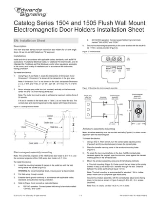
  • 1. © 2013 UTC Fire & Security. All rights reserved. 1 / 4 P/N 3100537 • REV 04 • REB 07FEB13 Catalog Series 1504 and 1505 Flush Wall Mount Electromagnetic Door Holders Installation Sheet EN: Installation Sheet Description The 1504 and 1505 Series are flush wall mount door holders for use with single doors. All are UL and ULC Listed and FM approved. Installation Install and wire in accordance with applicable codes, standards, such as NFPA publications 70 (National Electrical Code), 72 (National Fire Alarm Code), and 80 (Standard for Fire Doors and Fire Windows), and/or other regulations applicable to the country and locality of installation and in accordance with authorities having jurisdiction. To install the device: 1. Using Figure 1 and Table 1, locate the intersection of Dimension X and Dimension Y. Dimension Z is shown at the intersection in the gray area. Note: If dimension X or Y is not shown on the chart, extrapolate Dimension Z. (i.e., if X=7, and Y=30, Z = (27 5/8 - ((27 5/8 - 27 1/4)/2) => Z = 27 9/16 in. 2. Mount a single gang outlet box (not supplied) vertically on the horizontal center line and 5 in. from the top of the door. Note: The outlet box must be able to withstand a maximum holding force of 50 pounds. If X and Y intersect in the blank area in Table 2, do not install the box. The contact plate and electromagnet cannot be aligned with these dimensions. Figure 1: Locating the door holder Electromagnet assembly mounting Note: The combined projection of the 1504 series door holder is 3-7/ 16 in. and the combined projection of the 1505 series door holder is 2-7/ 16 in. To install the device: 1. Install the mounting brackets (2 pieces) in the outlet box with the field wiring below the bracket (Figure 3). WARNING: To prevent electrical shock, ensure power is disconnected. 2. Pull field wiring through conduit. 3. Establish earth-ground continuity in accordance with applicable codes, standards and authorities having jurisdiction. 4. Refer to Figure 2 and connect as instructed below: a. 120 VAC operation. Connect power field wiring to terminals marked "120V AC" and "COM." b. 24 VAC/DC operation. Connect power field wiring to terminals marked "24V AC/DC" and "COM." 5. Secure the electromagnet assembly to the cover bracket with the two #10- 32 × 7/8 in. screws provided (Figure 3). Figure 2: Terminal block Figure 3: Mounting the electromagnet assembly Armature assembly mounting Note: Armature assembly must be mounted vertically (Figure 4) to obtain correct alignment with the electromagnet. To install the device: 1. Using a 5/32 in. Allen wrench, turn the contact plate adjusting screw (Figures 5 and 6) counterclockwise to loosen the contact plate. 2. Place the transfer marking points in the armature mounting holes (Figure 4). 3. To locate the two mounting holes in the door, hold the contact plate centered against the magnet, open the door and press against the transfer marking points on the armature base. 4. Mount the armature assembly using one of the following methods: a. Thru-bolt mounting (Figure 5). Center punch the two holes (at the points marked in step 3) and drill 5/16 in. diameter through the door. Distance between the center points should equal 1 3/4 in. Note: Thru-bolt mounting is recommended for standard 1 3/4 in. hollow metal, hollow core or composite type wood doors. Secure the armature assembly, with the contact plate adjust screw facing down, to the door as shown in Figure 5 using (2) #1/4-20 × 2 in. screws (supplied). Note: For 2 in. doors, use two 1/4-20 × 2 1/4 in. bolts.
  • 2. 2 / 4 P/N 3100537 • REV 04 • REB 07FEB13 b. Surface concealed mounting (Figure 6). Measure two points for 1/8 in. holes drilled 1/2 in. on center equidistant from each marked point. Center punch the holes and drill 1/8 in. diameter × 1 1/4 in. deep. Install the concealed mounting plate using the two #10 × 1-1/2 in. screws provided. Note: Surface concealed mounting is not recommended for hollow metal, hollow core, or composite type wood doors. Align the holes for the concealed mounting plate in the armature base with the pins on the concealed mounting plate. Secure the armature assembly with the contact plate adjust screw facing down to the door by tightening the set screw. 5. Align the contact plate against the electromagnet. The contact plate must be centered and lie flat against the magnet to ensure sufficient holding force. Tighten the contact plate adjusting screw until the plate is firm but not set. Do not over tighten the contact plate. 6. Recheck alignment and adjust if necessary. 7. Adjust the door closer to exert 3 pounds of force when the door is open and armature and magnet are in contact. 8. Energize the electromagnet and check operation. Note: The unit will not operate without electrical power. Figure 4: Mounting the armature assembly Figure 5: Thru-bolt mounting (Cat. Series 1505 shown) Figure 6: Surface concealed mounting (Cat. Series 1504 shown) Table 1: Specifications Cat. no. Volts Amps 1504-AQN5 24 VAC 60 Hz 0.015 24 VDC 0.015 120 VAC 60 Hz 0.015 1505-AQN5 24 VAC 60 Hz 0.015 24 VDC 0.015 120 VAC 60 Hz 0.015 Table 2: Dimension chart (in inches (mm)) Y = Dimension of door width 28 30 32 34 36 38 40 42 44 46 48 X=Dimensionofdoorjambtowall 2 26 (660) 28 (711) 29 7/8 (759) 32 (813) 34 (864) 36 (914) 38 (965) 40 (1016) 42 (1067) 43 7/8 (1114) 45 5/8 (1159) 4 26 (660) 28 (711) 29 7/8 (759) 32 (813) 34 (864) 36 (914) 38 (965) 40 (1016) 42 (1067) 43 7/8 (1114) 45 5/8 (1159) 6 25 5/8 (651) 27 5/8 (702) 29 5/8 (752) 31 3/4 (806) 33 3/4 (857) 35 3/4 (908) 37 3/4 (959) 39 3/4 (1010) 41 3/4 (1060) 43 5/8 (1108) 45 3/8 (1153) 8 25 1/4 (641) 27 1/4 (692) 29 1/4 (743) 31 3/8 (797) 33 1/2 (851) 35 1/2 (902) 37 3/8 (949) 39 1/2 (1003) 41 1/2 (1054) 43 3/8 (1102) 45 1/4 (1149) 10 24 5/8 (625) 26 3/4 (679) 28 3/4 (730) 30 7/8 (784) 33 (838) 35 (889) 37 (940) 39 1/8 (994) 41 1/8 (1045) 43 (1092) 44 7/8 (1140) 12 23 3/4 (603) 25 7/8 (657) 28 (711) 30 1/8 (765) 32 1/4 (819) 34 3/8 (873) 36 3/8 (924) 38 1/2 (978) 40 5/8 (1032) 42 1/2 (1080) 44 3/8 (1127) 14 23 3/4 (603) 25 (635) 27 1/4 (692) 29 3/8 (746) 31 1/2 (800) 33 3/4 (857) 35 7/8 (911) 38 (965) 40 (1016) 42 (1067) 43 7/8 (1114) 16 21 3/4 (552) 24 (610) 26 1/4 (667) 28 1/2 (724) 30 3/4 (781) 33 (838) 35 1/8 (892) 37 1/4 (946) 39 3/8 (1000) 41 3/8 (1051) 43 3/8 (1102) 18 20 (508) 22 1/2 (572) 25 (635) 27 3/8 (695) 29 3/4 (756) 32 (813) 34 1/4 (870) 36 1/2 (927) 38 5/8 (981) 40 5/8 (1032) 42 1/2 (1080) 20 18 1/4 (463) 21 (533) 23 1/2 (597) 26 (660) 28 1/2 (724) 30 7/8 (784) 33 1/8 (841) 35 3/8 (899) 37 5/8 (956) 39 5/8 (1006) 41 5/8 (1057) 22 18 3/4 (476) 21 5/8 (549) 24 3/8 (619) 27 (686) 29 3/8 (746) 31 3/4 (806) 34 1/8 (867) 36 1/2 (927) 38 5/8 (981) 40 3/4 (1035) 24 22 1/2 (572) 25 1/2 (648) 28 1/8 (714) 30 5/8 (778) 33 1/8 (841) 35 5/8 (905) 37 7/8 (962) 40 (1016) 26 Do not install outlet box if 26 1/4 (667) 29 (737) 31 5/8 (803) 34 1/4 (870) 36 1/2 (927) 38 5/8 (981) 28 Dimensions X and Y intersect in this blank area. 29 3/4 (756) 32 1/2 (826) 34 7/8 (886) 37 1/8 (943) 30 The armature and electromagnet cannot be aligned. 27 3/4 (705) 30 5/8 (778) 33 (838) 35 3/8 (899) 32 31 3/8 (797) 33 7/8 (860)
  • 3. P/N 3100537 • REV 04 • REB 07FEB13 3 / 4 FR: Fiche D'Installation Description Les appareils des séries 1504 et 1505 sont des dispositifs à montage mural encastrés, conçus pour retenir une seule porte. Tous les modèles sont homologués UL et ULC et approuvés FM. Installation Posez et raccordez le câblage conformément à tous les codes et normes applicables, p. ex. publications NFPA 70 (National Electrical Code), 72 (National Fire Alarm Code) et 80 (Standard for Fire Doors and Fire Windows) et/ou tout autre règlement applicable dans le pays et la localité où a lieu l’installation, ainsi qu’aux exigences des autorités compétentes. Pour monter l'appareil: 1. À partir le la Figure 1, repérez l’intersection des dimensions X et Y dans le tableau 2. La dimension Z correspond à la valeur indiquée à cette intersection dans la partie grisée. Remarque: Si la dimension X ou Y ne figure pas dans le tableau, déterminez la dimension Z par extrapolation (p. ex., si X = 7 et Y = 30, Z = (27 5/8 - ((27 5/8 - 27 1/4)/2)) =>Z = 27 9/16 po. 2. Fixez une boîte de sortie de format simple (non fournie) verticalement sur l’axe central horizontal et à 5 po du haut de la porte. Remarque: La boîte de sortie doit pouvoir résister à une force maximale de retenue de 50 livres. Si l’intersection de X et Y est dans la partie blanche du tableau 2, N’installez PAS la boîte de sortie. Il est impossible d’aligner la plaque de contact et l’électroaimant avec ces dimensions. Figure 1: Emplacement du dispositif de retenue Montage de l’électroaimant Remarque: Une fois installé, le dispositif de retenue de porte de la série 1504 dépasse de la surface du mur de 3-7/16 po (87 mm); pour la série 1505, cette épaisseur est de 2-7/16 po (62 mm). Pour monter l'appareil: 1. Installer les supports de montage (2 pièces) dans la boîte de sortie, avec le câblage externe sous le support (Fig. 3). MISE EN GARDE: Pour éviter les chocs électriques, vérifiez que l’électricité est coupée. 2. Tirez les fils du circuit dans le conduit. 3. Établissez la continuité des masses (terre) conformément aux codes, normes et exigences pertinentes de l’autorité compétente. 4. Effectuez les raccordements comme suit en vous référant à la Figure 2: a. Modèles 120 V c.a. Branchez les fils du circuit externe aux bornes marquées «120V AC» et «COM». b. Modèles 24 V c.a./c.c. Branchez les fils du circuit externe aux bornes marquées «24V AC/DC» et «COM». 5. Fixez l’électroaimant au support-couvercle au moyen des 2 vis no 10-32 × 7/8 po fournies (voir Fig. 3). Figure 2: Bornier Figure 3: Montage de l’électroaimant Montage de l’armature Remarque: L’armature doit être montée verticalement (Fig. 4) pour être bien alignée avec l’électroaimant. Pour monter l'appareil: 1. Au moyen d’une clé hexagonale de 5/32 po, tournez vers la gauche la vis de réglage de la plaque de contact pour desserrer celle-ci. (Fig. 5 et 6). 2. Placez les points de transfert dans les trous de fixation de l’armature (Fig. 4). 3. Pour marquer l’emplacement des deux trous de fixation dans la porte, maintenez la plaque de contact centrée contre l’aimant, ouvrez la porte et appuyez contre les points de marquage de transfert sur la base de l’armature. 4. Fixez l’armature en utilisant l’une ou l’autre des méthodes suivantes: a. Fixation par boulons traversants (Fig. 5). Marquez au pointeau le centre des deux trous (aux endroits marqués à l’étape 3) et percez un trou de 5/16 po de diamètre au travers de la porte. La distance entre les deux centres devrait être de 1 3/4 po. Remarque: La fixation par boulons traversants est recommandée pour les portes standard de 1 3/4 po de type métalliques creuses, en bois à âme creuse ou composites. La vis de réglage de la plaque de contact étant dirigée vers le bas, fixez l’armature sur la porte comme illustrée sur la Fig. 5 au moyen de deux vis no 1/4-20 × 2 po (fournies). Remarque: Pour les portes de 2 po, utilisez 2 boulons de 1/4-20 × 2 1/4 po. b. Montage avec plaque dissimulée (Fig. 6). Marquez deux points, pour des trous de 1/8 po, à une distance de 1/2 po l’un de l’autre et centrés par rapport aux points marqués à l’étape 3. Marquez ces nouveaux points au pointeau et percez dans chacun un trou de 1/8 po de diamètre sur 1 1/4 po (32 mm) de profondeur. Fixez la plaque dissimulée au moyen des deux vis no 10 × 1 1/2 po fournies.
  • 4. 4 / 4 P/N 3100537 • REV 04 • REB 07FEB13 Remarque: La fixation avec plaque dissimulée n’est pas recommandée pour les portes métalliques creuses ni pour les portes en bois à âme creuse ou composites. Alignez les trous pour la plaque dissimulée dans la base de l’armature avec les tiges de la plaque de montage. La vis de réglage de la plaque de contact étant vers le bas, fixez l’armature à la porte en serrant la vis de blocage. 5. Alignez la plaque de contact contre l’électroaimant. La plaque de contact doit être centrée et doit bien prendre appui contre l’aimant pour obtenir une force de retenue suffisante. Serrez la vis de réglage de la plaque de contact jusqu’à ce que celle-ci soit bien maintenue, mais sans forcer. Ne serrez pas trop fort. 6. Vérifiez que l’alignement est toujours correct et ajustez au besoin. 7. Ajustez le ferme-porte pour qu’une force de 3 livres soit exercée lorsque la porte est ouverte et que l’armature et l’aimant sont en contact. 8. Vérifiez le fonctionnement du dispositif de retenue. Remarque: Le dispositif ne peut pas fonctionner sans électricité. Tableau 1: Dimensions (en pouces (mm)) Y = largeur de la porte 28 30 32 34 36 38 40 42 44 46 48 X=distanceentrelemontantdeporteetlemur 2 26 (660) 28 (711) 29 7/8 (759) 32 (813) 34 (864) 36 (914) 38 (965) 40 (1016) 42 (1067) 43 7/8 (1114) 45 5/8 (1159) 4 26 (660) 28 (711) 29 7/8 (759) 32 (813) 34 (864) 36 (914) 38 (965) 40 (1016) 42 (1067) 43 7/8 (1114) 45 5/8 (1159) 6 25 5/8 (651) 27 5/8 (702) 29 5/8 (752) 31 3/4 (806) 33 3/4 (857) 35 3/4 (908) 37 3/4 (959) 39 3/4 (1010) 41 3/4 (1060) 43 5/8 (1108) 45 3/8 (1153) 8 25 1/4 (641) 27 1/4 (692) 29 1/4 (743) 31 3/8 (797) 33 1/2 (851) 35 1/2 (902) 37 3/8 (949) 39 1/2 (1003) 41 1/2 (1054) 43 3/8 (1102) 45 1/4 (1149) 10 24 5/8 (625) 26 3/4 (679) 28 3/4 (730) 30 7/8 (784) 33 (838) 35 (889) 37 (940) 39 1/8 (994) 41 1/8 (1045) 43 (1092) 44 7/8 (1140) 12 23 3/4 (603) 25 7/8 (657) 28 (711) 30 1/8 (765) 32 1/4 (819) 34 3/8 (873) 36 3/8 (924) 38 1/2 (978) 40 5/8 (1032) 42 1/2 (1080) 44 3/8 (1127) 14 23 3/4 (603) 25 (635) 27 1/4 (692) 29 3/8 (746) 31 1/2 (800) 33 3/4 (857) 35 7/8 (911) 38 (965) 40 (1016) 42 (1067) 43 7/8 (1114) 16 21 3/4 (552) 24 (610) 26 1/4 (667) 28 1/2 (724) 30 3/4 (781) 33 (838) 35 1/8 (892) 37 1/4 (946) 39 3/8 (1000) 41 3/8 (1051) 43 3/8 (1102) 18 20 (508) 22 1/2 (572) 25 (635) 27 3/8 (695) 29 3/4 (756) 32 (813) 34 1/4 (870) 36 1/2 (927) 38 5/8 (981) 40 5/8 (1032) 42 1/2 (1080) 20 18 1/4 (463) 21 (533) 23 1/2 (597) 26 (660) 28 1/2 (724) 30 7/8 (784) 33 1/8 (841) 35 3/8 (899) 37 5/8 (956) 39 5/8 (1006) 41 5/8 (1057) 22 18 3/4 (476) 21 5/8 (549) 24 3/8 (619) 27 (686) 29 3/8 (746) 31 3/4 (806) 34 1/8 (867) 36 1/2 (927) 38 5/8 (981) 40 3/4 (1035) 24 22 1/2 (572) 25 1/2 (648) 28 1/8 (714) 30 5/8 (778) 33 1/8 (841) 35 5/8 (905) 37 7/8 (962) 40 (1016) 26 Ne pas installer la boîte de sortie si l’intersection 26 1/4 (667) 29 (737) 31 5/8 (803) 34 1/4 (870) 36 1/2 (927) 38 5/8 (981) 28 des dimensions x et y se trouve dans cette section blanche. 29 3/4 (756) 32 1/2 (826) 34 7/8 (886) 37 1/8 (943) 30 Il serait impossible d’aligner l’armature et l’électroaimant. 27 3/4 (705) 30 5/8 (778) 33 (838) 35 3/8 (899) 32 31 3/8 (797) 33 7/8 (860) Figure 4: Montage de l’électroaimant Figure 5: Fixation par boulons traversants (Série 1505 illustrée) Figure 6: Fixation avec plaque dissimulée (Série 1504 illustrée) Tableau 2: Caractéristiques électriques N° de cat. Volts Ampères 1504-AQN5 24 VAC 60 Hz 0.015 24 VDC 0.015 120 VAC 60 Hz 0.015 1505-AQN5 24 VAC 60 Hz 0.015 24 VDC 0.015 120 VAC 60 Hz 0.015 Contact information For contact information, see www.edwardssignaling.com.