The document describes a receiver and transmission circuit for an infrared signal.
The receiver circuit uses a TSOP1738 infrared sensor that outputs a high signal when it detects an interruption in the infrared signal. This triggers a 555 timer configured as a monostable multivibrator to output a pulse around 1 second. The microcontroller uses this input to control a 7-segment display and relay for a visitor counter.
The transmission circuit generates a 38 kHz infrared signal using a 555 timer configured as a monostable multivibrator. It produces a pulse width determined by the resistor and capacitor values, transmitting the 38 kHz signal that the receiver sensor detects.
General Principles of Intellectual Property: Concepts of Intellectual Proper...
Room illumination
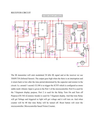
1. RECEIVER CIRCUIT
The IR transmitter will emit modulated 38 kHz IR signal and at the receiver we use
TSOP1738 (Infrared Sensor). The output goes high when the there is an interruption and
it return back to low after the time period determined by the capacitor and resistor in the
circuit. I.e. around 1 second. CL100 is to trigger the IC555 which is configured as mono
stable multi vibrator. Input is given to the Port 1 of the microcontroller. Port 0 is used for
the 7-Segment display purpose. Port 2 is used for the Relay Turn On and Turn off
Purpose.LTS 542 (Common Anode) is used for 7-Segment display. And that time Relay
will get Voltage and triggered so light will get voltage and it will turn on. And when
counter will be 00 that time Relay will be turned off. Reset button will reset the
microcontroller. Microcontroller based Visitor Counter.
2. TRANSMISSION CIRCUIT
This circuit diagram shows how a 555 timer IC is configured to function as a basic mono
stable multi vibrator. A mono stable multi vibrator is a timing circuit that changes state
once triggered, but returns to its original state after a certain time delay. It got its name
from the fact that only one of its output states is stable. It is also known as a ‘one-shot’.
In this circuit, a negative pulse applied at pin 2 triggers an internal flip-flop that turns off
pin 7′s discharge transistor, allowing C1 to charge up through
R1. At the same time, the flip-flop brings the output (pin 3) level to ‘high’. When
capacitor C1 as charged up to about 2/3 VCC, the flip-flop is triggered once again, this
time making the pin 3 output ‘low’ and turning on pin 7′s discharge transistor, which
discharges C1 to ground. This circuit, in effect, produces a pulse at pin 3 whose width t is
just the product of R1 and C1, i.e., t=R1C1.
IR Transmission circuit is used to generate the modulated 36 kHz IR signal. The IC555 in
the transmitter side is to generate 36 kHz square wave. Adjust the preset in the transmitter
to get a 38 kHz signal at the o/p. around 1.4K we get a 38 kHz signal. Then you point it
over the sensor and its o/p will go low when it senses the IR signal of 38 kHz.