
Recommandé
Contenu connexe
Tendances
Tendances (20)
Similaire à UNCONVENTIONAL MACHINING PROCESS
Similaire à UNCONVENTIONAL MACHINING PROCESS (20)
Dernier
Dernier (20)
UNCONVENTIONAL MACHINING PROCESS
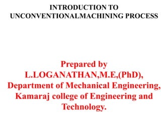
- 1. INTRODUCTION TO UNCONVENTIONALMACHINING PROCESS Prepared by L.LOGANATHAN,M.E,(PhD), Department of Mechanical Engineering, Kamaraj college of Engineering and Technology.
- 2. Syllabus • Unconventional machining Process • Need • Classification • Brief overview
- 3. WHAT IS UCM? An unconventional(non-traditional) machining process can be defined as a material removal process in which no direct contact between tool and work-piece occurs. In this type of machining process, a form of energy is used to remove unwanted material from a given workpiece.
- 4. Conventional Machining Process • Metal Removal ? • Nature of Contact ? • Scrap ?
- 5. Demerits • Disposal of Waste • By products of chips • Work holding Devices for larger cutting force • Heat Generation • Not possible without chips
- 6. Unconventional Manufacturing process • Unconventional Manufacturing process 1. Unconventional Machining process or Non Traditional Machining Process 2. Unconventional Forming process
- 7. Unconventional Manufacturing process Machining process • Metal Removal • No Direct Contact b/w tool and work piece Forming process • Metals are formed • Releases large amount of Energy in very short time interval
- 8. Need for UCM • Machining – produces finished products with high degree of accuracy • Conventional machining • Utilizes cutting tools (harder than workpiece material). • Needs a contact between the tool and workpiece. • Needs a relative motion between the tool and workpiece.
- 9. Need • • • • • • The need for higher productivity, accuracy and surface quality Improve the capability of automation system and decreasing their sophistication (decreasing the investment cost) requirements Very hard fragile materials difficult to clamp for traditional machining When the work piece is too flexible or slender When the shape of the part is too complex Internal and external profiles, or small diameter holes.
- 10. 12 Unconventional Machining Processes – Based on Energy
- 11. 13 Unconventional Machining Processes – Based Mechanism
- 12. 14 Unconventional Machining Processes – Based on Energy used for Removal
- 13. 15 Unconventional Machining Processes – Based on Transfer of Energy
- 14. 16 Mechanical Based Processes 1. Working principles 2. Equipment used 3. Process parameters 4. MRR 5. Variation in techniques used 6. Applications AJM WJM AWJM USM
- 15. 17 Electrical Based Processes 1. Working principle 2. Equipment used 3. Process parameters 4. Surface finish & MRR 5. Electrode/Tool 6. Power & Control circuits 7. Tool wear 8. Dielectric 9. Flushing 10. Applications Electrical EDM WEDM
- 16. 18 Chemical & Electrochemical Based Processes 1. Working principles 2. Etchants & Maskants 3. Techniques of applying maskants 4. Process parameters 5. Surface finish & MRR 6. Electrical circuits in case of ECM 7. Applications CHM ECM ECG ECH
- 17. 19 Thermal Based Processes 1. Working principles 2. Equipment used 3. Types 4. Beam control techniques 5. Applications LBM PAM EBM
- 18. Selection Process • Selection Process is based of following parameters – Physical Parameter – Shapes to be Machined – Process Capability – Economic consideration
- 19. Physical Parameter fluid Parameter ECM EDM EBM LBM PAM USM AJM Potential, V 5- 30 50-500 200 x 103 4.5 x 10³ 250 220 220 Current, A 40,000 15-500 0.001 2 600 12 1.0 Power, kW 100 2.70 0.15 20 220 2.4 0.22 Gap, mm 0.5 0.05 100 150 7.5 0.25 0.75 Medium Electrolyte Die electric Vacuum Air Argon NitrogenAbrasive grains Work Material M/C diff Tungsten carbide All Mtl All Mtl All Mtl Tungsten HSS carbide
- 20. Shapes to be Machined Process Machines Holes ( Micro, Small, deep,Shallow) LBM, EBM,ECM, USM & EDM Precision Work USM & EDM Horning ECM Etching ECM & EDM Grinding AJM & EDM Deburring USM & AJM Threading EDM Profile Cut PAM
- 21. Process Capability or Machining Characteristics Process MRR ( mm3/s ) Surface Finish (μm) Accuracy (μm) Power (kW/ cm3/ min LBM 0.10 0.4 – 6.0 25 2700 EBM 0.15 - 40 0.4 – 6.0 25 450 EDM 15 - 80 0.25 10 1.8 ECM 27 0.2 -0.8 50 7.5 PAM 2500 Rough 250 0.90 USM 14 0.2 – 0.7 7.5 9.0 AJM 0.014 0.5- 1.2 50 312.5
- 22. Process Economy Process Capital Cost Tool & Fixtures Power Requirement Efficiency EDM Medium High Low High CHM Medium Low High Medium ECM V. High Medium Medium V. Low AJM V. Low Low Low Low USM High High Low Medium EBM High Low Low V. High LBM Medium Low V. Low V. High PAM V. Low Low V. Low V. Low Convention al V. Low Low Low V. Low
- 23. Limitation • More Expensive • Slow Process • Commercial
- 24. UNIT 2 MECHANICAL ENERGY BASEDPROCESS B ME6004 UNCONVENTIONAL MACHINING PROCESSES
- 25. SYLLABUS Abrasive Jet Machining (AJM) Water Jet Machining (WJM) Abrasive Water Jet Machining (AWJM) Ultrasonic Machining. ( USM) Working Principles – equipment used – Process parameters – MRR-Variation in techniques used – Applications.
- 26. ABRASIVE JET MACHINING (AJM) Principle In Abrasive Jet Machining process, a high speed stream of abrasive particles mixed with high pressure air or gas which is injected on the work piece through nozzle
- 30. Typical AJM Parameters Abrasives used. Aluminum Oxide (Al o Silicon Carbide (Sic) Glass Powder. Dolomite ) 10 to 50 mic 25 to 50 mic 0.3 to 0.6 mm 200 grit size Working Medium. Dry air Gases ( Nitrogen or carbon dioxide)
- 31. Nozzle Material Tungsten Carbide Silicon carbonate ABRASIVE MATERIAL Abrasive material Grit size (μin) Orifice diameter (in) Aluminum oxide 10 - 50 0.005 - 0.018 Silicon carbide 25 - 50 0.008 - 0.018 Glass beads 2500 0.026 - 0.05
- 32. ADVANTAGES Low capital cost Less vibration No heat generated in the work piece Eco friendly Only one tool is required
- 33. DISADVANTAGES Low metal removal rate Abrasive powder can not be reused The machining accuracy is poor Nozzle wear rate is high
- 34. Water Jet Machining Principle In WJM, the high velocity of water jet comes out of the nozzle and strikes the material, its kinetic energy is converted into pressure energy including high stress in the work material. when this exceeds the ultimate shear stress of the material, small chips of the material get loosened and fresh surface is exposed.
- 36. PROCESS PARAMETERS Material removal rate(MRR) -Depends on the reactive force of the jet Reactive force = Mass flow rate (m) X jet velocity (V) Geometry and finish of work piece Wear rate of the nozzle
- 37. Advantages of water jet cutting There is no heat generated in water jet cutting; which is especially useful for cutting tool and other metals where excessive heat may change the properties of the material. Unlike machining or grinding, water jet cutting does not produce any dust or particles
- 38. Disadvantages of water jet cutting One of the main disadvantages of water jet cutting is that a limited number of materials can be cut economically. Thick parts cannot be cut by this process economically and accurately Taper is also a problem with water jet cutting in very thick materials. Taper is when the jet exits the part at different angle than it enters the part, and cause dimensional inaccuracy.
- 39. Applications Of WJM Process Water jet cutting is mostly used to cut lower strength materials such as wood, plastics and aluminum. When abrasives are added, (abrasive water jet cutting) stronger materials such as steel and tool steel can be cut.
- 40. Abrasive Water Jet Machining Principle: In abrasive water jet machining process a high stream of abrasive jet particles is mixed with pressurized water & injected through the nozzle on the work piece.
- 42. Advantages of Abrasive water jet cutting In most of the cases, no secondary finishing required No cutter induced distortion Low cutting forces on work pieces Limited tooling requirements Little to no cutting burr Typical finish 125-250 microns Smaller kerfs size reduces material wastages No heat affected zone
- 43. CONTD… Localizes structural changes No cutter induced metal contamination Eliminates thermal distortion No slag or cutting dross Precise, multi plane cutting of contours, shapes, and bevels of any angle.
- 44. Disadvantages of Abrasive water jet cutting Cannot drill flat bottom Cannot cut materials that degrades quickly with moisture
- 45. Ultrasonic Machining Principle In the Ultrasonic Machining process the material is removed by micro-chipping or erosion with abrasive particles. The tool forces the abrasive grits, in the gap between the tool and the work piece, to impact normally and successively on the work surface, thereby machining the work surface.
- 46. Contd…. In USM process, the tool , made of softer material than that of the work piece, is oscillated by the Booster and Sonotrode at a frequency of about 20 kHz with an amplitude of about 25.4 um(0.001 in).
- 49. PROCESS PARAMETER Effect of amplitude and frequency of vibration on MRR MRR is directly proportional to the first power of frequency for a fixed amplitude Theoretical M R R Frequency Actual M R R High amplitude Low frequency High frequency
- 50. CONTD… EFFECT `VELOCITY` MRR IS DIRECTLY PROPORTIONAL TO THE PARTICLE VELOCITY M R R Feed force Mean grain diameter Surface rough
- 51. CONTD.. EFFECT OF STATIC LOADING OR FEED FORCE: - MRR increases with an increase in feed force. EFFECT OF GRAIN SIZE: 1. - Grain size increases with an increase in MRR
- 52. Advantages of USM There is no cutting forces therefore clamping is not required except for controlled motion of the work piece Extremely hard and brittle materials can be easily machined There is no heat affected zone. Can machine harder metals Faster than EDM No tool wear at all. No heat affected zone. Better finish and accuracy.
- 53. USMApplications Hard, brittle work materials such as ceramics, glass, and carbides. Also successful on certain metals, such as stainless steel and titanium. • Shapes include non-round holes, holes along a curved axis. • “Coining operations” - pattern on tool is imparted to a flat work surface
- 55. Electrical Energy based processes • Electrical energy is directly used to cut the material to get the finalshape and size – Electrical discharge machining (EDM) – Wire cut Electrical Discharge Machining (WCEDM)
- 56. Electrical Discharge Machining (EDM) • Principle – Metal is removed by producing powerful electric spark discharge between the tool (cathode) and the work material(anode) – Also known as Spark erosion machining or electro erosion machining
- 57. Why EDM? • EDMhasthe following advantages: • 1. Cavities with thin walls and finefeatures canbe produced. • 2. Difficult geometry ispossible. • 3. Theuseof EDMis not affected bythe hardnessof the workmaterial. • 4. Theprocessis burr-free.
- 61. EDM • Construction and Working
- 63. EDM • Dielectric Fluid – Fluid medium which doesn’t conduct electricity – Dielectric fluids generally used are paraffin, white spirit, kerosene, mineral oil – Must freely circulate between the work piece and tool which are submerged init – Eroded particles must be flushed out easily – Should be available @reasonableprice – Dielectric fluid must be filtered before reuse so that chip contamination of fluid will not affect machining accuracy
- 64. EDM • Functions of dielectricfluid – Acts asan insulating medium – Coolsthe spark region & helps in keeping the tool and work piece cool – Carries away the eroded material along with it – Maintains aconstant resistance acrossthe gap – Remainselectrically non-conductive
- 65. EDM • Toolmaterials and tool wear – Metallic materials • Copper, Brass,Copper-tungsten – Non metallic materials • graphite – Combination of metallic and nonmetallic • Copper – graphite – Three most commonly used tool materials are • Copper, graphite, copper-tungsten
- 66. EDM • Tool materials – Graphite • Non-metallic • Canbe produced by molding, milling, grinding • Wide range of grades are available for wideapplications • It is abrasive and gives better MRRand surfacefinish • But costlier than copper – Copper • Secondchoice for tool material aftergraphite • Canbe produced by casting or machining • Cutools with very complex features are formed by chemical etching or electroforming – Copper-tungsten • Difficult to machine and also haslowMRR • Costlier than graphite andcopper
- 67. EDM • Selection of cutting toolis influenced by – Sizeof electrode – Volume of material to beremoved – Surfacefinish required – Toleranceallowable – Nature of coolantapplication • Basicrequirement of any tool materialsare – It should havelow erosionrate – Should be electrically conductive – Should havegood machinability – Melting point of tool should be high – Should havehigh electron emission
- 68. EDM • Tool wear – Tooldoes not comesin contact with thework – So,life of tool is long and lesswear takesplace Wear ratio = vol. of workmaterial removed vol. of electrodeconsumed • Toolwear ratio for – Brasselectrode is 1:1 – Copper of 2:1 – Copper tungsten is 8:1 – Graphite varies between 5 and 50:1
- 69. EDM • Metal Removal Rate(MRR) – Defined asvolume of metal removed per unit time – Depends upon current intensity and it increases with current – Usually a rough cut with heavy current and finishing cut with alesscurrent isperformed – MRRup to 80Cu.mm/S, canbeobtained – Surface finish of 0.25 microns isobtained – Tolerances of the order of ±0.05 to 0.13 mm are commonly achieved
- 70. EDM • Factorsaffecting MRR – Increases with forced circulation of dielectricfluid – Increases with capacitance – Increases up to an optimal value of work-tool gap, after that it drops suddenly – Increases up to an optimum value of spark discharge time, after that itdecreases – MRR is maximum, when the pressure is below atmospheric pressure
- 71. EDM • Power generating circuits – Resistancecapacitance circuit (RCCircuit) – R-C-LCircuit
- 72. EDM – Rotary pulse generator circuit – Controlled pulse generatorcircuit
- 73. EDM • ProcessParameters – Operating parameters • Electrical energy • Voltage • Time interval • Instantaneous current • Torque • Pulse width – Taper – Surface finish • Energy of the pulse • Frequency of operation – Current density
- 74. EDM • Characteristics of EDM Metal removaltechnique Byusing powerful electric spark Work material Electrically conductive materials Toolmaterial Copper, alloy of Zinc, yellow brass,Copper-Tungsten MRR 15 to 80Cu.mm/S Spark gap 0.005 to 0.05mm Spark frequency 200 to 500KHz Volts 30 to 250V Current 5 to 60A Temperature 10,000 degree celcius Dielectricfluid Petroleum basedHCfluids, Paraffin, White Spirit
- 75. EDM • Applications – Production of complicated and irregular profiles – Thread cutting in jobs – Drilling of microholes – Helical profile drilling – Curved hole drilling – Re-sharpening of cutting tool andbroaches – Re-machining of die cavities without annealing • Recent developments – EDMchange from using relaxation circuit to faster and more efficient impulsecircuits – Instead of using Cu;WCis used aselectrode
- 76. EDM • Advantages – Canbe used to machine various conductive materials – Givesgood surface finish – Machining of very thin section ispossible – Doesnot leaves any chips or burrs on the workpiece – High accuracy is obtained – Fine holes canbe easily drilled – Process once started does not need constant operators attention – It is aquicker process – Well suited to machine complicatedcomponents
- 77. EDM • Disadvantages – Used to machine only electrically conductive materials – Non-metallic compounds such as plastics, ceramics or glasscannever be machined – Suitable for machining small work pieces – Electrode wear and overcut are seriousproblems – Perfect square corners cannot be machined – MRRisslow – Power requirement is high – The surface machined has been found to have micro holes
- 78. Wire Cut Electrical Discharge Machining (WC-EDM) • Principle – Metal is removed by producing powerful electric spark discharge between the tool (cathode) and the work material(anode) – Also known as Spark erosion machining or electro erosion machining
- 80. WCEDM
- 81. WCEDM • Applications – Best suited for production of gears, tools, dies, rotors, turbine blades andcams • Disadvantages – Capital cost is high – Cutting rate isslow – Not suitable for large workpieces
- 82. WCEDM • Features / Advantages ofWCEDM – Manufacturing electrode – Electrode wear – Surface finishing – Complicated shapes – Time utilization – Straight holes – Rejection – Economical – Cycletime – Inspection time
- 83. UNCONVENTIONALMACHINING PROCESS– UNIT4 Chemical and Electrochemical Energy Basedprocesses
- 84. Chemical EnergyBasedprocesses • Metal is removed from the work piece through a controlled etching of work piece material in contact with thechemical solution • Example – Chemical Machining (CHM)
- 85. Electrochemical EnergyBased processes • Material is removed by ion displacement of work piece material in contact with a chemical solution • Example – Electro-Chemical Machining (ECM) – Electro-Chemical Grinding (ECG) – Electro-Chemical Honing (ECH) – Electro-Chemical deburring (ECD)
- 86. Chemical Machining (CHM) • Also called asChemical Milling (CHM)
- 87. CHM • Etchant – Chemical reagent used to removed the metal from work piece – Metal is removed by the chemical conversion of metal into metallicsalt S.No Material Etchant 1 Aluminum Causticsoda 2 Steel HCl/ HNO3Acid 3 Stainlesssteel FeCl 4 Magnesium HNO3Acid 5 Titanium HNO3Acid
- 88. CHM • Maskant – Areas of work piece which are covered with a resistant material called amaskant or resist • Methods of masking – Scribed or peeledmaskants – Photo resists maskants S.No Material Maskant 1 Aluminum Butyl rubber, neoprene rubber 2 Magnesium Polymers 3 Titanium Translucent chlorinated polymers 4 Nickel Neoprene 5 Ferrous metals Polyvinyl chloride, polyethylene
- 89. CHM • Metal RemovalRate – Depends upon selected etchant – Fastwith certain etchant – Etchrate is limited to 0.02 to 0.04mm/min – Etching rate and depth of cut are high for hard materials and low for softermaterials – Surface finish of the order of5µ are produced – Sizeof work piece depends upon the sizeof tank – With optimum time, temperature and solution control; accuracies of order ±0.01 mm isobtained
- 90. CHM • Classification of CHM – Chemicalblanking • Material is etched entirely on the workpiece • Used to cut out the parts from thin sheet metal or foil sheets – Chemicalmachining • Material is selectively etched from certain areas on work piece • Usedto remove material from thicker workpieces • Application of CHM – Usedin manufacturing burr freecomponents – Applied where the depth of metal removal is critical to few microns and the tolerances areclose
- 91. CHM • Advantages of CHM – Burr free components areproduced – Most difficult to machine components aremachined – High surface finish is obtained – Stressfree components are produced – No need of skilledlabor – Tooling cost is low – Complex contours canbe easily machined – Hard and brittle materials canbemachined – Both facesof work piece are simultaneouslymachined
- 92. CHM • Disadvantages – MRRislow – Manufacturing cost is high – Largefloor area isneeded – Not possible to produce sharpcorners – Work piece thickness that can be machinedis limited
- 93. Electro Chemical machining (ECM) • Principle – Faraday’s first law • Amount of material dissolved or deposited is proportional to the quantity of electricity passed – Faraday’s second law • Amount of charge produced in the material is proportional to its electrochemical equivalent of material – Work piece connected to positive terminal (cathode) – Tool connected to negative terminal (anode)
- 94. ECM
- 95. ECM
- 96. ECM • Analysis of metal removal – Mild D.C. Voltage of about 5 to 30V is applied between the tool and workpiece – Current flows through the electrolyte with charged ions – The following reactions are possible at the cathode (tool) Na++e- = Na Na+H2O= Na(OH)+H+ 2H++2e- =H2 – Thus there is no deposition on tool and only hydrogen gasis evolved
- 97. ECM • Similarly following reaction occur at theanode Fe2+ +2e- FeCl2 • Fe • Fe+++2Cl- • Fe+++2 (OH)- • FeCl2+2(OH) Fe(OH)2 Fe(OH)2+ 2Cl- • This shows that work piece goesinto solution and machined – Bycombining the faraday’s first and second law of electrolysis we get • Where, – W – massof ions dissolved in Kg – E– Equivalent weight of substancedissolved – T-time in S – FaradaysConstant =96,500 Coulombs =26.8 Amp.Hr
- 98. ECM • Tool material, tool design andinsulation – Any material which is a good conductor of electricity canbe used astool material – Thegeneral requirement of tool material in ECM are • Must be agood conductor of electricity • Must be chemically inert to the electrolyte • Must be easilymachinable • Must be rigid enough to take up the load due to fluid pressure – Thetool is made hollow for drillingholes – Outer surface of the tool must be insulated by vinyl, teflon, enamels or high temperaturevarnish
- 99. ECM • While designing the tool, thefollowing aspectsare taken into consideration – Determine the tool shape – Design the tool by considering the electrolyte • Electrolyte – Carries current between tool and workpiece S.No Material Electrolyte 1 Febasedalloys 20%NaClsolution in water 2 Ni basedalloys Mixture of brine and sulphuricacid 3 Tibased alloys 10%HF+10%HCl+10%HNO3 4 Co-Crbased alloys NaCl 5 WCbasedalloys Strong alkaline solutions
- 100. ECM • Theessential characteristics of electrolyteare – Should be agood conductor of electricity – Should have non-corrosive property – Should be non-toxic – Should have low viscosity • Surface finish – Depends mainly on • Machining voltage • Toolfeed rate • Temperature of electrolyte • Concentration of electrolyte
- 101. ECM • Applications – Tomachine complicated profiles like jet engine blades, turbine blades, turbinewheels – Todrill small deep holes in nozzles – Tomachine cavities and holes of irregularshapes – Tomachine blind holes and pockets in forgingdies – Tomachine hard and heat resistant materials • Limitations – Sharpinternal corners cannot bemachined – Postmachining cleaning isneeded – Tooldesign is very complicated – Control mechanism is needed to maintain high tolerances
- 102. ECM • Characteristics Metal removaltechnique Faraday’slaw of electrolysis Work material Difficult to machine Toolmaterial Copper, brassor steel Voltage 5 to 30v Current 50 to 40000A MRR 27 Cu.mm/S Electrolyte 20%NaClsolution in water, mixture of brine insulphuric acid Surfacefinish 0.2 to 0.8µ Tolerance 0.005mm Specific powerconsumption 7 W/Cu.mm/min
- 103. ECM • Advantages – MRRishigh – Wear and tool tear isnegligible – Machining is done at low voltage – Intricate and complex shapes can be machined easily – Machined work surface is free of stress – No cutting forces are involved – High surface finish of order 0.2 to 0.8µ isobtained – Tolerance of 0.005mm canbe obtained – No burrs are produced
- 104. ECM • Disadvantages – Non conducting materials cannot bemachined – Initial investment is quite high – More spaceis required – Machining process is comparatively low – Power consumption is 100 times more than conventional machining – Difficulty in designing aproper tooling system – Constant monitoring is required
- 105. ECM S.No EDM ECM 1 Work piece is submerged in dielectric fluid Work piece need not to be submerged in electrolyte 2 Toolwear takes place No tool wear 3 Control system is required No control system isrequired 4 Machining cannot be doneat low voltages Machining canbe done at low voltages 5 MRRis slow compared to ECM MRRis high compared to EDM 6 Lessenergy isconsumed More energy isconsumed
- 106. Electro Chemical Grinding (ECG) • Materials that cannot be easily shapeddueto their extreme hardness canbeground – Example • Cemented carbides • Hardened steel • Principle – Work is machined by the combined action of electrochemical effect and conventionalgrinding operation
- 107. ECG
- 108. ECG
- 109. ECG • Processparameters – Current density – Electrolyte – Feed rate – Grinding wheel speed • Applications – Best suited for high precision grinding ofhard metals like WC – Also suited to cut thin sections ofhard materials without anydamage
- 110. ECG • Advantages – Tool wear is negligible – Work is free of surface cracksand not subjectedto any structural changes – Burr and stress free components are produced – Good surface is obtained – Surface finish of 0.2 to 0.4µ areproduced – Accuracy of 0.01mm canbe achieved – Intricate paths canbe machined without any distortion
- 111. ECG • Disadvantages – Initial cost ishigh – Power consumption is high – MRRislow – Non conductive materials cannot bemachined – Maintenance cost is high – Tolerance achieves is low – Preventive measures are needed against corrosion of electrolyte
- 112. Electro Chemical Honing (ECH) • Similar to ECG • ECHusesrotating and reciprocating, non- conducting bonded honing stones instead of a conducting grinding wheel
- 113. ECH • Advantages – MRRis faster with reduced tool wear – Burr and stress free components are produced – Lesspressure is required between honing stones and work piece – Usedto machine burred edges – Noise and distortion are reduced
- 115. Thermal Energybased Processes • Heat energy is concentrated on a small area of work piece to melt and vaporize the tiny bits of workmaterial • Required shape is obtained by the continued repetition of theprocess • Example 1. Electron BeamMachining (EBM) 2. LaserBeamMachining (LBM) 3. PlasmaArc Machining (PAM)
- 116. Electron BeamMachining (EBM) • A beam of high velocity electrons travelling at half the velocity of light (1.6 X 10^8 m/S) are focused on the work piece to remove the metal • Principle – When high velocity beam of electrons strike the work piece its kinetic energy is converted intoheat – This concentrated heat raises the temperature of work piece material and vaporizes a small amount of it, resulting in removal of material from work piece
- 117. EBM • Types – Machining inside the vacuumchamber – Machining outside the vacuumchamber
- 118. EBM
- 119. EBM • Processparameters – Control of current – Control of spotdiameter – Control of focal distance of magneticlens • Applications – Usedfor micromachining operations – Usedto drill holes in pressure differentialdevices – Usedto remove small broken taps fromholes – Usedto machine low thermal conductivityand high melting point materials
- 120. EBM Acceleratingvoltage 50 to 200KV Beam current 100 to 1000µA Electronvelocity 1.6X10^8 m/S Medium Vacuum Work piecematerials All materials Depth ofcut Up to 6.5mm MRR Up to 4.Cu.mm/S Specific powerconsumption 0.5 to 50KW Power density 6500 billion W/mm^2
- 121. EBM • Advantages – Excellent process for micromachining – Very small holes and holes of different sizedcanbe machined – No mechanical contact between tool and workpiece – Quick process – Easily automated – Closetolerances are obtained – Brittle and fragile materials canbemachined – Physicaland metallurgical damage to work piece are less
- 122. EBM • Disadvantages – MRRis verylow – Costof equipment ishigh – Not suitable for large workpieces – Little taper is produced onholes – Vacuumrequirements limits the sizeof workpiece – Not suitable to produce perfectlycylindrical profiles – Applicable for thin materials – Energyconsumption is high
- 123. Laserbeam Machining (LBM) • LASER – Light Amplification by Stimulated Emissionof Radiation • LikeEBM;LBMis also used to drill micro holes up to 25µ on the work piece by • Principle – Laser beam is focused means of lens to give extremely high energy density to melt and vaporize thework material
- 124. LBM
- 125. LBM
- 126. LBM • Accuracy – To get best possible results, the material should be placed within atolerance of ±0.2mm focalpoint • Lasingmaterials – Solid laser • Rubylaser, neodymium doped Yttrium –Aluminum –Garnet (Nd-YAG)laser and neodymium doped glass laser – GasLaser • Canbe operated continuously • Produces exceptionally high monochromaticity and high stability of frequency • Example – Carbon dioxide Laser – Helium-Neon Laser
- 127. LBM • Processing with LASER S.No Special characteristics of aLASER beam Cutting processcharacteristics 1 Canbe focused to amaximum or minimum intensity asneeded MRRis maximum tominimum 2 Canbe moved rapidly on work piece Cutting of complexshapes 3 Projected on the work piece ata particular distance from thelens Remote cutting over longstand-off distances 4 Dedicated to on-line processes Re-routing is not necessary 5 Power is shared on ajob Twoor more cutssimultaneously
- 128. LBM • Machining applications of LBM – Laserin metal cutting – Laserin drilling – Laserin welding • Conduction limited welding • Deep penetration welding – Laserfor surface treatment – Other applications • Sheet metal trimming • Blanking • Resistor trimming
- 129. LBM • Characteristics Metal removaltechnique Heating, melting & vaporization ofmaterial by using high intensity of laserbeam Work material All materials expect those having highthermal conductivity Tool Laserbeam of wavelength range 0.3 to 0.6µ Power density 10^7 W/sq.mm Output energylaser 20 J MRR 6 Cu.mm/min Pulse duration 1 millisecond Dimensionalaccuracy ±0.025mm Medium Atmosphere Efficiency 10 to 15% Specificpower consumption 1000 W/Cu.mm/min
- 130. LBM • Advantages – Micro sizedholes are produced – Soft materials like rubber canbemachined – No tool wear – No direct contact between tool and workpiece – Dissimilar materials canbe easily welded – Easily automated – Hardness of material does not affect theprocess – Heat affected zone is very small – Deepholes of short diameter canbe easilydrilled
- 131. LBM • Disadvantages – Initial investment ishigh – Operating cost is also quite high – Highly skilled operators are needed – Rateof production islow – Safety procedures to be followed strictly – Overall efficiency is extremely low – Life of flash lamp isshort – Machined hole is not round andstraight
- 132. PlasmaArc Machining (PAM) or PlasmaJet machining (PJM) • Principle – Material is removed by directing a high velocity jet of high temperature [11000 to 28000 deg. celcius] ionized gas on the work piece, which in turn melts the material from workpiece
- 133. PAM
- 134. PAM
- 135. PAM • Gasesused in PAM – Gasused should not affect the electrode orwork piece to bemachined S.No Gas or GasMixture Material to bemachined 1 Nitrogen- hydrogen, Argon- hydrogen Stainless steel, non ferrous material 2 Nitrogen-hydrogen, Compressed air Carbon & alloy steel, castiron 3 Nitrogen, nitrogen-hydrogen Argon-hydrogen Aluminum, Magnesium
- 136. PAM • Types – Direct arc plasma torch – Indirect arc plasma torch • Accuracy of PAM – Accuracy of 1.4mm isobtained – Accuracy on width of slots and diameter ofholes is ordinarily from ±4mm to 150 mm thickplates
- 137. PAM • Characteristics Metal removaltechnique Heating, melting and vaporising by using plasma Work material All materials which conductelectricity Tool Plasmajet Velocity of plasmajet 500 m/S Power range 2 to 200KW Current Ashigh as600 A Voltage 40 to 250V Cuttingspeed 0.1 to 7m/min MRR 145 Cu.mm/min
- 138. PAM • Processparameters – Standoff distance – Thermo physical and metallurgical properties of plasma – Cutting speed or velocity of plasmajet • Applications – Usedfor profile cutting – Used for turning and milling of hard to machine materials – Canbe used for stack cutting, shapecutting – Uniform thin film spraying of refractory materials – Usedto cut alloy steels, SS,copper, nickel, titanium, Aluminum and alloy of copper andnickel
- 139. PAM • Advantages – Usedto cut anymaterial – Cutting rate ishigh – Cancut plain carbon steel four times fasterthan ordinary flame cutting process – Usedfor rough turning of very difficultmaterials • Disadvantages – Produces tapered surface – Noise protection isnecessary – Equipment cost is high – Protection of eyesis necessary for theoperator – Work surface may undergo metallurgical changes