06 2015 pesgm_wllv_vsc

Poster Presentation at the IEEE PES General Meeting. This paper presents a PMU-based state estimation algorithm that considers the presence of voltage source converter- based high voltage direct current (VSC-HVDC) links. The network model of a VSC-HVDC link with its control modes is developed and then combined with an AC model to accomplish a hybrid AC/DC network model. The measurement model in this algorithm considers the properties of PMU measurements, thus separating the network model with measurements. Additionally, DC link measurements are assumed to be sampled synchronously, time-stamped and reported at the same rate as PMU measure- ments. Then, by applying the nonlinear weighted least squares (WLS) algorithm, a PMU-based state estimator can solve for both AC and DC states simultaneously. To validate the algorithm, a simulation study for a 6-bus hybrid AC/DC test system is shown in this paper.
Recommandé

Recommandé
Contenu connexe
Tendances
Tendances (17)
En vedette
En vedette (10)
Similaire à 06 2015 pesgm_wllv_vsc
Similaire à 06 2015 pesgm_wllv_vsc (20)
Plus de Luigi Vanfretti
Plus de Luigi Vanfretti (20)
Dernier
Dernier (20)
06 2015 pesgm_wllv_vsc
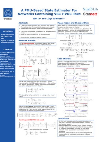
- 1. CONTACT INFORMATION A PMU-Based State Estimator For Networks Containing VSC-HVDC links Wei Li¹ and Luigi Vanfretti¹,² KEYWORDS: State estimation VSC-HVDC link PMU Hybrid AC and DC state estimation • A PMU-only state estimator (SE) algorithm that reduces the nonlinearities of network and measurement models. • It safeguards the network model from missing meas. • VSC-HVDC link model in the presence of different control modes. • Allows to solve hybrid AC/DC SE simultaneously. • Demonstrated using a six-bus test system. Abstract: Network Models: The AC network model is composed of a line with series admittance and shunt admittance, and transformers. Figure 1: AC line with transformer VSC station model: Figure 4: Voltage magnitudes at Bus 4 for multiple snapshots Conclusion: • A PMU-only state estimator for networks containing VSC-HVDC links has been introduced and validated by a six-bus test system. • Although estimation accuracy during system dynamic changes decreases compared to that for steady state, it is expected to be greatly improved as long as the network model is updated in each measurement snapshot. • Therefore, future work will focus on including network model update or topology processing into the state estimator. Figure 2. Basic diagram of a VSC station Case Studies: A six-bus hybrid AC/DC test system is applied to validate the proposed VSC model and SE algorithm. A line breaker was opened at t = 2 s and after three cycles it was re-closed at t = 2.06 s. Figure 5: DC voltage at rectifier side for multiple snapshots Figure 6: DC current for multiple snapshots CONTACTS: 1.School of Electrical Engineering Electric Power Systems Department KTH Royal Institute of Technology Teknikringen 33 100 44 Stockholm -SE Email: wei3@kth.se Email: luigiv@kth.se 2.Statnett SF, R & D, Oslo, Norway E-mail: luigi.vanfretti@statnett.no. The AC line connecting bus i and VSC station i can be represented by the AC branch model with Y = 0 to build up the relation between bus voltage and current phasors with converter voltage and current phasors. The converter is represented by an average value model (AVM). Vector-current control is commonly used for VSC’s high- level control scheme. Either active power or DC voltage can be selected for d-axis control; either reactive power or AC voltage can be selected for q-axis control. Point-to-point VSC-HVDC link model: Meas. model and SE Algorithm: When PMUs are used for data acquisition, the state variables can be measured directly. If the conventional meas. model is used, the choice of state variables in z can not be uniquely determined, this affects the estimation accuracy of different states. Therefore, the new measurement model is formulated as: Performance index J(x): Iteration procedure: 1 1.5 2 2.5 3 3.5 4 0.8 0.9 1 Time (s) |V|(p.u.) Vmag-true Vmag-meas. Vmag-est. 1 1.5 2 2.5 3 3.5 4 10 -5 10 0 Time (s) |V|(p.u.) Vmag-estimation-residual 1 1.5 2 2.5 3 3.5 4 0.95 1 1.05 Time (s) Vrdc(p.u.) Hvdc-true Hvdcm Hvdc-est 1 1.5 2 2.5 3 3.5 4 10 -5 10 0 Time (s) Vrdc(p.u.) Vrdc-residual-error 1 1.5 2 2.5 3 3.5 4 0.6 0.8 1 Time (s) Idc(p.u.) Hvdc-true Hvdcm Hvdc-est 1 1.5 2 2.5 3 3.5 4 10 -4 10 -2 Time (s) Idc(p.u.) Idc-residual-error Figure 3. A point-to-point VSC-HVDC link model