LATEST IEEE PROJECTS ABSTRACT-Airport baggage conveyour using ivrs&embedded systems
•Télécharger en tant que DOC, PDF•
0 j'aime•736 vues

project details......project details......dont hesitate, pl call me..........,dont hesitate, pl call me.........., thanks R.ASHOK KUMAR MAASTECH 89. RANGARAJAPURAM MAIN ROAD(NEAR SBI BANK) KODAMBAKKAM CHENNAI-600024 PH:044-24844676 ASHOK KUMAR-098402 34766 ipt/projects full details....PL VISIT http://www.maastechindia.com (projects list,abstract,video,photo gallery)

Recommandé
Recommandé
Contenu connexe
Plus de ASHOKKUMAR RAMAR
Plus de ASHOKKUMAR RAMAR (20)
Dernier
Dernier (20)
LATEST IEEE PROJECTS ABSTRACT-Airport baggage conveyour using ivrs&embedded systems
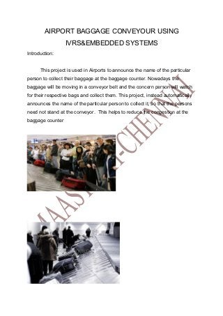
- 1. AIRPORT BAGGAGE CONVEYOUR USING IVRS&EMBEDDED SYSTEMS Introduction: This project is used in Airports to announce the name of the particular person to collect their baggage at the baggage counter. Nowadays the baggage will be moving in a conveyor belt and the concern person will watch for their respective bags and collect them. This project, instead automatically announces the name of the particular person to collect it, so that the persons need not stand at the conveyor. This helps to reduce the congestion at the baggage counter
- 2. Operation: A RFID Tag is attached to every baggage. A RFID reader is fixed on the conveyor. So when the baggage comes near the reader, it’s code is read by the reader and it checks the database for the name of the particular person and announces it through the speaker. For announcing the name we have used a APR 9600 which is a voice storage and retrieval device. An LCD Display is also provided to display the name in the lcd. For the conveyor movement we have used a stepper motor. The Main Heart of the system is the PIC Embedded 16F877 Microcontroller which is used to control every operation. The Project Block diagram is given below. BLOCK DIAGRAM:
- 3. RFID TAG(FIXED SUITCASE) POWER SUPPLY RFID READER LCD DISPLAY STEPPER MOTER PIC 16F877 DRIVER BOARD STEPPER MOTER RELAY STEPPER MOTER DRIVER RELAY POWER SUPPLY APR 9600 MIC SPEAKER RFID Baggage 2 Reader Baggage 1
- 4. RF technology is used in many different applications, such as television, radio, cellular phones, radar, and automatic identification systems. The term RFID (radio frequency identification) describes the use of radio frequency signals to provide automatic identification of items. RFID is similar in concept to bar coding. Bar code systems use a reader and coded labels that are attached to an item, whereas RFID uses a reader and special RFID devices that are attached to an item. Bar code uses optical signals to transfer information from the label to the reader; RFID uses RF signals to transfer information from the RFID device to the reader. Radio waves transfer data between an item to which an RFID device is attached and an RFID reader. The device can contain data about the item, such as what the item is, what time the device traveled through a certain zone, perhaps even a parameter such as temperature. RFID devices, such as a tag or label, can be attached to virtually anything – from a vehicle to a pallet of merchandise. RFID technology uses frequencies within the range of 50 kHz to 2.5 GHz. An RFID system typically includes the following components: • An RFID device (transponder or tag) that contains data about an item • An antenna used to transmit the RF signals between the reader and the RFID device • An RF transceiver that generates the RF signals • A reader that receives RF transmissions from an RFID device and passes the data to a host system for processing In addition to this basic RFID equipment, an RFID system includes application-specific software.
- 5. BASIC TAG ASSEMBLY TAG IC’S BASIC TAG IC ARCHITECTURE RFID tag IC’s are designed and manufactured using some of the most advanced and smallest geometry silicon processes available. The result is impressive, when you consider that the size of a UHF tag chip is around 0.3 mm2 VIEW OF THE 125 kHz CARD EMPLOYED IN OUR PROJECT
- 6. PIC MICRO CONTROLLER Other than the normal Microcontrollers PIC Family supports more features, so we have chosen PIC 16F877 as the main controller. The Main features and Peripherals features are discussed below. 3.1 Core Features: • High performance RISC CPU • Only 35 single word instructions to learn • All single cycle instructions except for program Branches which are two cycle • Operating speed: DC - 20 MHz clock input DC - 200 ns instruction cycle • Up to 8K x 14 words of FLASH Program Memory, Up to 368 x 8 bytes of Data Memory (RAM) • Interrupt capability (up to 14 sources) • Direct, indirect and relative addressing modes
- 7. • Power-on Reset (POR) • Power-up Timer (PWRT) and Oscillator Start-up Timer (OST) • Processor read/write access to program memory • Wide operating voltage range: 2.0V to 5.5V • Low-power consumption: - < 0.6 mA typical @ 3V, 4 MHz - < 1 µA typical standby current Peripheral Features: • Timer0: 8-bit timer/counter with 8-bit prescaler • Timer1: 16-bit timer/counter with prescaler, can be incremented during SLEEP • Timer2: 8-bit timer/counter with 8-bit period register, prescaler and postscaler • 10-bit multi-channel Analog-to-Digital converter • Synchronous Serial Port (SSP) with SPI (Master mode) and 12C(Master/Slave) • Universal Synchronous Asynchronous Receiver Transmitter (USART/SCI) with 9-bit address detection • Parallel Slave Port (PSP) 8-bits wide, with external RD, WR and CS controls (40/44-pin only)