Smart Power Amplifier
•
7 j'aime•1,510 vues

The document discusses improving the efficiency and linearity of RF power amplifiers. It proposes using a technique called outphasing which decomposes the input signal into constant amplitude signals. Additionally, it introduces using specially optimized nonlinear Q-filters to process the decomposed signals in order to improve the spectral content without sacrificing the peak-to-average power ratio. This enhances the linearity and relaxes the stringent alignment requirements of traditional outphasing amplifiers, making the technique more practical to implement. The key innovation is the use of these nonlinear Q-filters applied in the digital domain to optimize the tradeoff between spectral content and signal crest factor.

Recommandé
Contenu connexe
Tendances
Tendances (20)
Similaire à Smart Power Amplifier
Similaire à Smart Power Amplifier (20)
Plus de Magdi Mohamed
Plus de Magdi Mohamed (7)
Dernier
Dernier (20)
Smart Power Amplifier
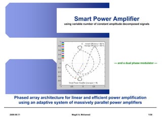
- 1. Smart Power Amplifier using variable number of constant amplitude decomposed signals --- and a dual phase modulator --- Phased array architecture for linear and efficient power amplification using an adaptive system of massively parallel power amplifiers 2008:06:11 Magdi A. Mohamed 1/30
- 2. Power Amplifiers Classification nonlinearity and efficiency in RF power amplifiers Type* Linearity* Efficiency* A very high very low (~50%) A/B B high low (~78%) B/C C medium medium (~80%) : : low high : E very low very high (~90%) *Linearity: for EDGE, 56 dBc at 400 KHz offset from carrier is “very high” *Efficiency when transistor is at full power *Type/Class E is “switched-mode” 2008:06:11 Magdi A. Mohamed 2/30
- 3. Power Amplifiers Classification nonlinearity concerns in RF power amplifiers • Linearity is defined by standard bodies: FCC, ETSI • Makes sure not to affect neighboring channels • Enforcing less distortion => Less interference => Less loss of information • Usually specified as Signal to Interferer Noise Ratio • Linearity specification is technology dependant 2008:06:11 Magdi A. Mohamed 3/30
- 4. Power Amplifiers Classification efficiency needs in RF power amplifiers • Efficiency == Less Wasted Energy • Efficiency => Less Operational Expenses (OP-EX) => Lower Electrical Bills => Money Gain (+$) • Efficiency => Long Battery Life for Mobiles • Efficiency => Environmentally Friendly • Inefficiency => Heat Dissipation => Cooling Requirements => Noise because of Fans => More Heat Sink => Significantly Increased Size and Weight => Money Loss (-$) 2008:06:11 Magdi A. Mohamed 4/30
- 5. Outphasing Power Amplifiers of Enhanced Data Rates for GSM Evolution (EDGE) Signals I 1 (t ) ⎫ ⎪ Ie ⎬ S1 (t ) ⎧ I (t ) EDGE filter Nonlinear Q1 (t ) ⎪ ⎪ Map ⎭ Modulator PA ⎪ ⎪ S (t )⎨ Se RF Combiner I 2 (t ) ⎫ ⎪ ⎪ ⎪ ⎬ S 2 (t ) Q2 (t ) ⎪ Nonlinear ⎪Q(t ) ⎩ EDGE filter Map ⎭ Modulator PA Qe EDGE Signal Generation Modulation, amplification, and combining reconstructs the original EDGE signal Se Outphasing means ( I e , Qe ) At any point in time, Se=S1+S2, decomposing the signal vector but S1 and S2 have constant Se Se into two vectors S1 and S2 radiuses. with constant amplitudes S2 The intersection of those (0,0) (vectors rotating in circles of circles defines the outphased constant radiuses) S1 signals S1 and S2 2008:06:11 Magdi A. Mohamed 5/30
- 6. Prior Art Search for RF power amplification techniques Competing Technologies a) Digital Pre-Distortion b) Outphasing Implementation of Outphasing 1) Lookup Tables 2) Inverse Sine & Inverse Cosine Computations 3) Complex Computation of the Square Root Function Types of Decomposition A) 2-Phase Decomposition B) N-Phase Decomposition (Fixed Number of Signals = N) 2008:06:11 Magdi A. Mohamed 6/30
- 7. Closest Prior Art Ericsson fixed number of decomposed signals Title: Linear amplification system and methods using more than two constant length vectors Inventor: Paul Wilkinson Dent Assignee: Ericsson Inc., Research Triangle Park, NC (US) Number: US 6,311,046 Date: October 30, 2001 Issues: » fixed number of decomposed signals » complex combiner hardware 2008:06:11 Magdi A. Mohamed 7/30
- 8. The New Idea Smart Power Amplifier Concept and Computations for Generating Variable Number of Constant Amplitude Decomposed Signals in Real-Time S5 S5 S4 S1 S3 ( I e , Qe ) ( I e , Qe ) S4 S2 Se S3 S1 Se S2 (0,0) (0,0) 2008:06:11 Magdi A. Mohamed 8/30
- 9. The Invention Smart Power Amplifier (SPA) - Phased Array Architecture Adaptive PA Array S1 aS1 S2 aS2 S3 aS3 S aS Decomposer Combiner Si aSi Promise Sn aSn Linearity of Type A together with the Efficiency of Type E Power Amplification 2008:06:11 Magdi A. Mohamed 9/30
- 10. Demonstrations 2008:06:11 Magdi A. Mohamed 10/30
- 11. Demonstrations 2008:06:11 Magdi A. Mohamed 11/30
- 12. Advantages of SPA characteristics and promises 1. Efficiency is not compromised for linearity as done with the conventional outphasing power amplifiers. 2. By using constant amplitude signals, we completely by-pass the issues of signal distortion due to the nonlinearity of individual power amplifiers. 3. Performs variable phase decomposition at the cost of two phase decomposition plus a minimal constant overhead, regardless of the number of available PAs. 4. For a given design, accuracy and efficiency requirements can be met by identifying the maximum number of PAs for the proposed architecture. 5. Can be used with other kinds of signals, and not just with EDGE signals. 6. Selection of maximum number of PAs is performed only once for each design (EDGE, CDMA, … etc.), and offline. 7. Can be used in base-stations as well as in wireless handsets. 8. Can be efficiently implemented as software or hardware (requires few cycles). 9. Solution is transparent to receivers. 2008:06:11 Magdi A. Mohamed 12/30
- 13. Dual Phase Modulator for improved efficiency and linearity of RF power amplifiers An extremely inexpensive and novel solution for the alignment problems in Outphasing Power Amplifiers using Q-filter Techniques 2008:06:11 Magdi A. Mohamed 13/30
- 14. Problem and Solution Problem: Outphasing is a technique used to improve RF power amplifier efficiency without trading-off linearity. It is rarely used nowadays due to stringent branch alignment requirements imposed by stringent spectral requirements for digital wireless transmission standards. Usually phase misalignment as little as 3 degrees between the two branches can cause spectral emissions and ACPR failures. Solution: We are proposing a new architecture where the two outphased signals go through special DSP filtering (using nonlinear Q-filters) optimized to improve spectral content (and thus relaxing the alignment requirement up to 8 degrees or higher) without sacrificing the desirable low Peak-To-Average Power Ratio (Crest Factor) of the outphased signals. 2008:06:11 Magdi A. Mohamed 14/30
- 15. I1 (t ) ⎫ ⎪ Ie Nonlinear ⎬ S 1 (t ) ⎧ I (t ) EDGE filter Q 1 (t ) ⎪ Modulator ⎪ Map ⎭ PA ⎪ ⎪ S (t ) ⎨ Se RF Combiner I 2 (t ) ⎫ ⎪ ⎪ ⎪ ⎬ S 2 (t ) Nonlinear ⎪Q (t ) ⎩ EDGE filter Q 2 (t ) ⎪ ⎭ Modulator PA Qe Map e.g. EDGE Signal Modulation, amplification, and combining Generation Existing Outphasing Solution reconstructs the original EDGE signal Se Adding specially optimized DSP filtering (with nonlinear Q-filters) can dramatically improve spectral content without sacrificing low Crest Factor I1 (t ) ⎫ ⎪ Ie Nonlinear ⎬ S 1 (t ) ⎧ I (t ) EDGE filter Q 1 (t ) ⎪ Optimized Modulator PA ⎪ Map ⎭ Q-Filter ⎪ ⎪ S (t ) ⎨ Se RF Combiner I 2 (t ) ⎫ ⎪ ⎪ ⎪ ⎬ S 2 (t ) Optimized Nonlinear ⎪Q (t ) ⎩ EDGE filter Q 2 (t ) ⎪ ⎭ Modulator PA Qe Map Q-Filter e.g. EDGE Signal Modulation, amplification, and combining Generation Q-filter Based Solution reconstructs the original EDGE signal Se 2008:06:11 Magdi A. Mohamed 15/30
- 16. Spectral Contents improved by about 10dB, thus leading to more relaxed alignment requirements 2008:06:11 Magdi A. Mohamed 16/30
- 17. Crest Factor degraded by only 0.67dB, thus still maintaining low Peak-To-Average Power Ratio (Our experiments show that using FIR linear filters does not maintain good Crest Factor, while optimizing the Q-filter showed good control and trading-off spectral contents versus Crest Factor) Original EDGE Outphased Signal After Applying Optimized Signal Before Q-filtering Nonlinear Q-filter CF=3.5dB CF=0dB CF=0.67dB 2008:06:11 Magdi A. Mohamed 17/30
- 18. Using Linear FIR-Filter Crest Factor gets worse than original signal Outphased 1 FIR-Filtered 1 Good Crest Factor Bad Crest Factor Bad Spectral Content Good Spectral Content Outphased 2 FIR-Filtered 2 Good Crest Factor Bad Crest Factor Bad Spectral Content Good Spectral Content Original Signal Amplify then Combine (e.g. EDGE) to Get Original Signal Constellation Diagrams 2008:06:11 Magdi A. Mohamed 18/30
- 19. Using Nonlinear Q-Filter Note that Crest Factor and Spectral Content gets better Outphased 1 Q-Filtered 1 Good Crest Factor Good Crest Factor Bad Spectral Content Good Spectral Content Outphased 2 Q-Filtered 2 Good Crest Factor Good Crest Factor Bad Spectral Content Good Spectral Content Original Signal Amplify then Combine (e.g. EDGE) to Get Original Signal Constellation Diagrams 2008:06:11 Magdi A. Mohamed 19/30
- 20. Phase Misalignment Effect 10o 60o Error Vector Magnitude (EVM) = 1 – 2*sin(30+10/2)= 14% 3GPP Spec ~ 17% Thus, up to 10o of phase error is tolerable. 2008:06:11 Magdi A. Mohamed 20/30
- 21. Prior Art Linear amplification systems and methods using more than two constant length vectors: 6311046, Ericsson Inc., Oct 30, 2001 http://www.google.com/patents?vid=USPAT6311046&id=Q2sIAAAAEBAJ&dq=outphasing+ericsson Describes a method to improve alignment and spectral contents, but relies on using four branches with conjugate signals, which degrades efficiency considerably and adds need to four modulators and more complex architecture. Hybrid Chireix/Doherty amplifiers and methods: 6133788, Ericsson Inc., Oct 17, 2000 http://www.google.com/patents?vid=USPAT6133788&id=KQcGAAAAEBAJ&dq=outphasing+ericsson Describes a way to increase efficiency by using special combining technique, but will still suffer from traditional outphasing problems, like branch alignment accuracy …etc. Outphasing modulator: 7009447, Intel Corporation, Mar 7, 2006 http://www.google.com/patents?vid=USPAT7009447&id=_bJ3AAAAEBAJ&dq=outphasing Does not describe how to solve the alignment problem. It details a method to outphase the signals, but will still suffer from traditional outphasing problems, like branch alignment accuracy …etc. Method and apparatus to match output impedance of combined outphasing power amplifiers: 7030714, Intel Corporation, Apr 18, 2006 http://www.google.com/patents?vid=USPAT7030714&id=g9J3AAAAEBAJ&dq=outphasing Describes a unique way of combining both branches to achieve maximum efficiency, but will still suffer from traditional outphasing problems, like branch alignment accuracy …etc. RF power amplifier and methods for improving the efficiency thereof: 6825719, Intel Corporation, Nov 30, 2004 http://www.google.com/patents?vid=USPAT6825719&id=d9oRAAAAEBAJ&dq=outphasing Describes a way to control the phase at the output of the PA, but will still suffer from traditional outphasing problems, like branch alignment accuracy …etc. 2008:06:11 Magdi A. Mohamed 21/30
- 22. Benefits • Improve user experience by improving battery life. It is estimated that using this technique, PA can achieve about 25% more efficiency than traditional methods. • Improve cost by using much cheaper and smaller nonlinear PA operating in Class C. It is estimated that we only need half the size PA when using filtered outphasing to achieve same PA performance, besides no need to any linearity requirements on the PA thus improving yield. • Eliminate need of costly outphasing alignment techniques. • Shift PA performance optimization to the digital domain instead of the RF domain, giving much more controllability and ease of design, thus improving Time-To-Market. • Achieve a new method that allows improving PA efficiency (and thus battery life) without compromising linearity, and have all the controls in the digital domain. • Easy to implement and far superior to other outphasing or PA linearization techniques. • Achieve a practical architecture for current generation wireless standards with high Crest Factor (like HSUPA), and for next generation wireless standards with high Crest Factor (like WiMAX and other OFDM standards). • High Crest Factor is imposing battery life constrains and cost constrains (due to need of bigger linear PA) that can be solved by using very low Crest Factor techniques. • Extendable to Smart Power Amplifiers. 2008:06:11 Magdi A. Mohamed 22/30
- 23. Backup 2008:06:11 Magdi A. Mohamed 23/30
- 24. Q-Measure Concept Fuzzy Measure Axioms Q-Measure Extensions (2003) Let A, B ⊂ X be non-intersecting sets for any choice of λ >-1, λ!=0, define: • Boundary conditions: m ( Φ ) = 0, m ( X ) = 1 ∏ (1 + λf i ) − 1 xi ∈ A q ( A) = , λ ≥ -1, λ ≠ 0 • Monotonicity: A1 ⊂ A2 → m ( A1 ) ≤ m ( A2 ) ∏ (1 + λf xi ∈ X i ) −1 • Continuity: where fi ε [0,1] are density generators guaranteed for discrete spaces Convergence Behavior of Q-Measures Probability Measure (1933) 1.05 replaces monotonicity by additivity: 1.025 p ( A U B ) = p ( A) + p ( B ) Scaling Factor, fn 1 0.975 C as e 1 C as e 2 Sugeno λ-Measure (1975) 0.95 C as e 3 0.925 adds one more axiom: 0.9 g ( A U B ) = g ( A) + g ( B ) + λ g ( A) g ( B ) 0.875 0 2 4 6 8 10 12 for a unique λ that satisfies g(X)=1 I te ra ti o n , n 2008:06:11 Magdi A. Mohamed 24/30
- 25. Q-Measures in a nutshell X x1 x2 x3 A∪ B = X A q-measures provide A∩ B = Φ x6 x5 x4 more expressive and α = f ( A) > 0 computationally attractive β = f ( B) > 0 B=Ac nonlinear models λ ≥ −1 x7 x8 x9 ρ = f ( A ∪ B) = α + β + λαβ > 0 for uncertainty α α q ( A) = = q(Ac) management ρ α + β + λαβ when modeling a q( B) = β = β 1.0 λ<0 complex system, ρ α + β + λαβ belief α/ρ it’s an oversimplification λ=0 ∂q( A) probability to assume that the >0 β/ρ ∂α interdependency among ∂q( A) <0 λ>0 ∂β plausibility information sources is ∂q( A) linear <0 ∂λ q(A) 0 β/ρ α/ρ 1.0 2008:06:11 Magdi A. Mohamed 25/30
- 26. Q-Filter Node and evidence accumulation for n-tap window and m-level signal S(t) s1 ... sn e(m-1)(t) m-1 s1 (m-1) sn (m-1) . . . . . . . . . . . . . . . . . . . . . e(i)(t) i Ai q(Ai) . . . . . . . H(i,j) . . . . . . . . . . . . . . + e(t) e(3)(t) 3 e(2)(t) 2 e(1)(t) 1 s1 (1) sn (1) f Processor λ 2008:06:11 Magdi A. Mohamed 26/30
- 27. Q-Filter Computations N=5 Tap Case - Nonlinearity, Adaptivity, and Model Capacity h4 Signal Value h(xi) Aα h3 α h1 h2 h5 i ∏ (1 + λf xi ∈ A i ) −1 x1 x2 x3 x4 x5 Window Slots q ( A) = , λ ≥ -1, λ ≠ 0 f1 f2 f3 f4 f5 ∏ (1 + λf xi ∈ X i ) −1 Density Generators q(Aα) λ Nonlinearity Controller q({x4, x3, x1, x2, x5})=1.0 q({x4, x3, x1, x2}) Total area is the Q-Filter output value q({x4, x3, x1}) q({x4, x3}) Adaptive Weight q({x4}) α q(Φ)=0.0 h5 h 2 h 1 h 3 h4 Threshold h5<h2< h1<h3< h4 Case 2008:06:11 Magdi A. Mohamed 27/30
- 28. Kernel Structure and model capacities ξ00000 ξ10000 ξ01000 ξ00100 ξ00010 ξ00001 ξ11000 ξ10100 ξ10010 ξ10001 ξ01100 ξ01010 ξ01001 ξ00110 ξ00101 ξ00011 ξ11100 ξ11010 ξ11001 ξ10110 ξ10101 ξ10011 ξ01110 ξ01101 ξ01011 ξ00111 ξ11110 ξ11101 ξ11011 ξ10111 ξ01111 ξ11111 Lattice representation for a q-measure of size, n=5 ξ b , …, b = q({xj | bj=1, j=1, …n}) 1 n i.e. ξ00000 = q(Φ) and ξ01101 = q({x2,x3 ,x5}) 2008:06:11 Magdi A. Mohamed 28/30
- 29. Fast Q-Filter 1. A fast method that replaces resorting (quadratic complexity for worst case) of moving window contents by deletions and insertions (linear complexity for worst case) when processing q-filter operations. 2. Data structures to implement the method. 3. Static memory allocation. h5 h5 f3 f2 f0 f4 f1 2008:06:11 Magdi A. Mohamed 29/30
- 30. Sample Execution 1 2 3 4 5 6 7 8 9 Time Slot 9 3 5 7 2 4 6 1 8 Time Series 5 2 3 4 1 1-Index 4 1 5 2 3 2-Index 3 4 1 5 2 3-Index 5 2 3 4 1 4-Index 4 1 2 3 5 5-Index 2008:06:11 Magdi A. Mohamed 30/30