Completely electronic, Gems Liquid Level Transmitters provide
reliable and durable remote tank gauging. A wide variety of material
combinations provide compatibility for most liquid media. Gems
XM- & XT-800 Series provide solutions for most small to mid-size tanks
in both process and OEM applications; for deeper tanks (to 18 feet) look
to Gems 36000 and 66000 Series.
1. C-1
LEVELSENSORS–CONTINUOUS
Visit www.GemsSensors.com for most current information.
C
B
A
C
B
A
C
B
A
SWITCHES
A & B CLOSEDA & B CLOSED
SWITCHES
A, B & C CLOSEDA, B & C CLOSED
SWITCHES
B & C CLOSEDB & C CLOSED
REED SWITCHES TRANSMITTER HOUSING
PERMANENT MAGNETPERMANENT MAGNET
FLOAT
XM SERIES NON-SIGNAL CONDITIONE
YOUR
INSTRUMENTAT
4-20 mA SIGNAL CONDITIONER
OPTION B
GEMS
RECEIVER
OPTION A
UNDERGROUND
TANK
GEMS
REC
XT SERIES,
SIGNAL
CONDITIONED
TRANSMITTER
XM SERIES NON-SIGNAL CONDITIONED TRANSMITTER
YOUR
INSTRUMENTATION
4-20 mA SIGNAL CONDITIONER
OPTION B
GEMS
RECEIVER
OPTION A
UNDERGROUND
TANK
GEMS/DIGITAL
RECEIVER
XT SERIES,
SIGNAL
CONDITIONED
TRANSMITTER
GEMS Continuous Electrical Output Transmitters
Provide Direct Liquid Measurement
Lengths to 18 feet (5.5 m)
Alloys or Engineered Plastic Wetted Parts
Analog Output
Completely electronic, Gems Liquid Level Transmitters provide
reliable and durable remote tank gauging. A wide variety of material
combinations provide compatibility for most liquid media. Gems
XM- & XT-800 Series provide solutions for most small to mid-size tanks
in both process and OEM applications; for deeper tanks (to 18 feet) look
to Gems 36000 and 66000 Series.
Gems experienced engineering and sales staff can provide customized
solutions for applications not satisfied by the standard transmitters
shown in this catalog. Do not hesitate to contact Gems if you require a
configuration not shown here.
Single Probe or Complete Systems
As a component, Gems transmitters provide the output options
compatible with most programmable controllers and other digital
receivers. Combined with Gems Digital Receivers you can create a
complete tank gauging system.
Typical Applications
Consider GEMS’ versatile transmitters for all your continuous liquid
level monitoring needs — water, diesel, lube oils and fuels, as well as
various chemical and petrochemical liquids. Here are just a few areas
where GEMS’ transmitters are used:
• Utilities • Beverage Industry • Medical • Pharmaceuticals • OHV
• Food Processing • Wineries • Printing • HVAC • Semiconductor
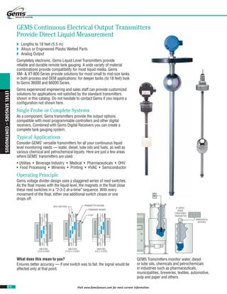
Operating Principle
Gems voltage divider design uses a staggered series of reed switches.
As the float moves with the liquid level, the magnets in the float close
these reed switches in a “2-3-2 at-a-time” sequence. With every
movement of the float, either one additional switch closes or one
drops off.
What does this mean to you?
Ensures better accuracy — if one switch was to fail, the signal would be
affected only at that point.
GEMS Transmitters monitor water, diesel
or lube oils, chemicals and petrochemicals
in industries such as pharmaceuticals,
municipalities, breweries, textiles, automotive,
pulp and paper and others.
2. C-2
LEVELSENSORS–CONTINUOUS
Visit www.GemsSensors.com for most current information.
Tank Depth
Maximum
Pressure
Primary
Material
Resolution Output
Transmitter
Series
Less Than
12 Feet
(3.7 m)
150 psi
(10 bar)
Alloy
1/4 inch
(6.4 mm)
10-30 VDC Proportional XM-800/860
Signal Conditioned XT-800/860
50 psi
(3.4 bar)
Engineered
Plastic
1/4 inch
(6.4 mm)
10-30 VDC Proportional XMP-800
Signal Conditioned XTP-800
300 psi
(2 bar)
Alloy
1/2 inch
(12.7 mm)
0-12 VDC Proportional XM-860
Signal Conditioned XT-860
1/4 inch
(6.4 mm)
10-30 VDC Proportional XM-800
Signal Conditioned XT-800
12 to 18
Feet
(3.7 m to
5.5 m)
500 psi
(35 bar)
Alloy
1/2 inch
(12.7 mm)
10-30 VDC Proportional
XM-66400
XM-36490
Signal Conditioned
XT-66400
XT-36490
2000 psi
(138 bar)
Alloy
1/2 inch
(12.7 mm)
10-30 VDC Proportional XM-66400
Signal Conditioned XT-66400
INTERFACE #1 TRANSMITTER
INTERFACE #2 TRANSMITTER
ABSOLUTE LEVEL TRANSMITTER
LOW SPECIFIC GRAVITY LIQUID
EMULSION
HIGH SPECIFIC GRAVITY LIQUID
ZENER
BARRIERS
RAIL MOUNT
NON-HAZARDOUS AREA
HAZARDOUS AREA
fLOaT TypE – INTRODUCTION
Contents Page Start
XM/XT-800 Series ................................................... C-3
XM/XT-860 Series ................................................... C-7
XMP/XTP-800.............................................. C-10
XM/XT-36490............................................... C-13
XM/XT-66400............................................... C-13
Signal Conditioning Modules.................... C-16
Receivers ....................................................D-24
Only a Float Can Show True Interface!
• By design or otherwise, dissimilar liquids often reside in the tank —
one floating atop another. Most tank gauging methods are limited
in these cases, and can only indicate the level of the uppermost
surface. With GEMS Transmitters, you can easily monitor the
interface between liquids…including the emulsions and slurries that
sometimes form between them.
• By adjusting the density of the magnetic float, GEMS can adapt the
transmitter to monitor the interface of a broad range of media. This
principle applies to oil and water, slurries, acids, bilge and other
dissimilar liquids.
• In conjunction with low level alarms, or automatic controllers, GEMS
Transmitters will help assure that only the “correct” liquid is taken
from a tank, or introduced into a process system.
Selection Guide
Notes:
1. Proportional Voltage = DC voltage proportional to liquid level and source voltage.
Ex. 5 VDC input, 0-5 VDC output.
2. Signal Conditioned = Regulated 0-5 VDC, 0-10 VDC, 0-12 VDC and 4-20 mA outputs.
Any non-voltage-producing sensor or switch is rendered intrinsically
safe for hazardous locations when properly connected to the output of
GEMS Zener Barriers. These are described in Section I.
Intrinsic Safety
GEMS transmitters are intrinsically safe for
hazardous area operation when properly
connected to a GEMS Zener Barrier, a solid-
state, energy limiting device. Any need for
explosion-proof housings or special wiring
of any kind is eliminated. GEMS Zener
Barriers are variously UL, FM, CSA and MSHA
approved. See Section I.
Got Mud?
Here's a tip. Gems Float
Sensors are the best, most
reliable method to monitor
mud pits. See our Large Size
Alloy models on Page C-13,
and use with the 8" float for
best results.
Use multiple Gems
Transmitters to accurately
monitor proportions of
dissimilar liquids and
emulsions within a single
tank.
3. C-3
LEVELSENSORS–CONTINUOUS
Visit www.GemsSensors.com for most current information.
1epyT
TPN˝2/1
2epyT
TPN˝4/1-1
3epyT
TPN˝2
4epyT
egnalF#051˝3
6epyT
egnalFyratinaS˝2/1-2
lairetaMmetS leetSsselniatS613rossarB leetSsselniatS613
lairetaMgnitnuoM leetSsselniatS613rossarB eletSsselniatS613roleetSnobraC leetSsselniatS613
lairetaMpotStaolF sgniRpirGOM7-51-HPOCMRA.S.S:stinUleetSsselniatS;sgniRpirGreppoCmuillyreB:stinUssarB
*erutarepmeTgnitarepO
rodetnuoMxoB.JhtiW
srenoitidnoClangiSMX
04-:liO ° 032+otF ° 04-(F ° 011otC ° 081+otretaW,)C ° 2.28(F ° taolFNanuB—)C
04- ° 032+otF ° 04-(F ° 011otC ° taolFleetSsselniatS—)C
detnuoMmetShtiW
srenoitidnoClangiS
5+ ° 061+otF ° 51-(F ° 07+otC ° )C
erusserPgnitarepO egaPtxeNeeS;epyTtaolFnotnednepeD
.xaM,htgneLllarevO )ylno4&3sepyT(epiP)mc663(˝441;gnibuT)mc381(˝27
3/4˝ FLATS
(19.0 mm)
1-1/4˝
(31.8 mm)
1-1/4˝
(31.8 mm) SQ.
1/2˝ NPT
2-3/4˝
(69.8 mm)
1/2˝ NPT
2-1/4˝
(57.2 mm)
2-1/2˝
(63.5 mm)
1-1/4˝
NPT
1˝ SQ.
(25.4 mm)
1-1/2˝
(38.1 mm)
2-1/2˝
SANITARY
FLANGE
3-Day
3-Day
Qwik Configured
Available for up to 5 units
Built & Shipped
in 3 Days!
Built & Shipped
in 3 Days!
Lengths
to 12 ft!
Small Size – Alloys
XM/XT-800 Series – Compact Analog Sensors
Stainless or Brass Construction
1/4˝ Resolution
Lengths to 144 inches (366 cm)
OEM Configurations Available
These compact transmitters feature the rugged durability of stainless steel or brassThese compact transmitters feature the rugged durability of stainless steel or brass
construction. The XM-800 series provides analog output, and can be combined withconstruction. The XM-800 series provides analog output, and can be combined with
GEMS Digital Meter Receiver Stations and compact Level Cubes described in thisGEMS Digital Meter Receiver Stations and compact Level Cubes described in this
catalog. Our versatile XT-800 Series adds a choice of signal conditioning for use withcatalog. Our versatile XT-800 Series adds a choice of signal conditioning for use with
GEMS digital bargraph receivers or other digital display and control equipment.
Approvals
XM-800 and XT-800 Series transmitters may carry the following commercial
approvals:
FM Approved, Explosion-Proof (J-Box and Stainless Steel Float required).FM Approved, Explosion-Proof (J-Box and Stainless Steel Float required).FM Approved, Explosion-Proof (J-Box and Stainless Steel Float required).
UL-Recognized.UL-Recognized.UL-Recognized.
XM-800 Series transmitters only:XM-800 Series transmitters only:XM-800 Series transmitters only:
CSA CertifiedCSA CertifiedCSA CertifiedCSA CertifiedCSA CertifiedCSA CertifiedCSA CertifiedCSA CertifiedCSA Certified
XT-800 Series transmitters only:
FM Approved, Intrinsic Safety (J-Box and Stainless Steel Float required).FM Approved, Intrinsic Safety (J-Box and Stainless Steel Float required).FM Approved, Intrinsic Safety (J-Box and Stainless Steel Float required).
1. Mounting Types
* Consult factory for higher temperature ranges.
Ordering is Easy! See Page C-5.
Easy online ordering too!
4. C-4
LEVELSENSORS–CONTINUOUS
Visit www.GemsSensors.com for most current information.
For Overall Lengths To 72˝ For Lengths Greater Than 72˝ (144˝ Max.)
Float Material Buna N Stainless Steel Buna N Stainless Steel
Float Dimensions
Compatible Mountings 1, 2, 3, 4, 6 1, 3, 4 1, 3, 4, 6 1, 3, 4 3, 4 3, 4
Part Number 1642552
43359 156490 43590 69654 52084
Min. Liquid Spec. Gravity .55 .55 .70 .75 .55 .75
Operating Pressure, Max.1
150 psi (10 bar) 150 psi (10 bar) 80 psi (6 bar) 300 psi (21 bar) 150 psi (10 bar) 300 psi (21 bar)
Operating Temp., Max.
Water: 180°F (82°C)
Oil: 230°F (110°C)
230°F (110°C)3 Water: 180°F (82°C)
Oil: 230°F (110°C)
230°F (110°C)*
Float Factor – X
Float Part
Number
X
164255 2.0˝ (50.8)
43359 2.5˝ (63.5)
156490 2.062˝ (52.4)
43590 3.437˝ (87.3)
69654 2.687˝ (68.3)
52084 3.625˝ (92.1)
Inch (mm)
Series Input Voltage Output Signal Part Number Electrical Termination
Compatible Mountings
Type 1 Type 3 Type 4
XM-800 10 to 30 VDC Proportional Voltage —
Lead Wires (3),
#22 AWG, 24˝ (60.9 cm),
PTFE Jacket
• • •
XT-800
8 to 24 VDC* 0-5 VDC 51965 Lead Wires,
#22 AWG, 24˝ (60.9 cm),
PTFE Jacket
• • •
14 to 30 VDC* 0-12 VDC 51970 • • •
8 to 24 VDC* 0-5 VDC 52536
Junction Box
• •
15 to 30 VDC* 0-12 VDC 52537 • •
10 to 40 VDC
4-20 mA 52555 • •
4-20 mA 112300 Panel Mount with Plug-in Base • • •
1-7/8˝
(47.6 mm)
DIA. TYP.
5/16˝
(8 mm)
1-13/16˝
( 46.0 mm)
TYP.
2-1/16˝
( 52.4 mm)
DIA. TYP.
2-3/4˝
(69.8 mm)
TYP.
5/16˝ (8 mm)
1-1/4˝
(31.8mm)
DIA.
TYP.
1-5/16˝
(33.3mm)
TYP.
5/16˝
(7.9mm)
1.63˝
(40.9mm)
DIA.
TYP.
1.40˝
(35.6mm)
5/16˝
(7.9mm)
1.86˝
(47.2mm)
DIA. TYP.
1.81˝
(46mm)
1/2˝
(12.7mm)
2.04˝ (51.7mm)
DIA. TYP.
2.68˝
(68mm)
1/2˝
(12.7mm)
B
INCHES
OF
INDICATION
C
LOWEST
LEVEL
HIGHEST
LEVEL
2˝ NPT
J-BOX
4-9/16˝
(115.9mm)
2. Float Types
Based on the overall length required by your tank, select from two main subsets of
floats below; further refine selection based on material and performance parameters.
Notes:
1. @ Ambient Temperature
2. Recommended for Type 2 mounting only.
3. Consult factory for higher temperature range.
3. To Determine Dimensions
Typical
Configuration B: Overall Length = Inches of Indication + C + X (See Table at Right)
C: Distance From Bottom of Mounting to Float Stop (Customer Specified):
• 1/4˝ (6.4mm) Minimum
• 1-1/4˝ (31.8mm) Minimum on Type 1, XT Series only.
Calculating Length
To find Overall Length when Inches or Indication is known:
• Inches of Indication + C* + X = Overall Length
To find Maximum Inches of Indication when Overall Length is known:
• Overall Length - C* - X = Maximum Inches of Indication
*C dimension is determined by customer.
4. Input/Output
For XM-800 Series, no special output designation is necessary.
For XT-800 Series, specify the desired signal conditioning by Part Number.
Additional information about GEMS signal conditioning modules is found on Page C-16.
* Stem mounted.
fLOaT TypE
5. This is a Request for a Quote
Order P.O.# ______
Quantity Needed ____________
Date Required ____/____/_____
Shipping Method:____________
Partials Accepted: Yes
No
Name __________________________________________
Company ________________________________________
Street __________________________________________
City_______________________ State ____ Zip__________
Phone ( _____ ) __________________________________
Fax ( _____ ) _____________________________________
Photocopy This Form
Use one form for each product
type you are selecting.
Product Check List
C-5 Visit www.GemsSensors.com for most current information.
Float
Selected
Indicating Length
(Half Inches)
+
“C” Dimension
±1/16˝ (1.8 mm)
+
Float Factor X
Inch (mm)
=
Overall
Length
43359 + + 2.5 (63.5) =
43590 + + 3.44 (87.3) =
52084 + + 3.63 (92.1) =
69654 + + 2.69 (68.3) =
156490 + + 2.06 (52.3) =
164255 + + 2 (50.8) =
Gems Sensors & Controls
One Cowles Road
Plainville, CT
06062-1198
tel 860.747.3000
fax 860.747.4244
www.gemssensors.com
Sensors & Controls
This form may also be completed online at
gemssensors.com for RFQ.
Floattypetransmitters–small,alloys
Float Type Level Transmitters – XM/XT-800 Series
Application Environmental Conditions
This information is essential to the accurate and proper operation of
your GEMS configurable sensors. Please complete fully and accurately.
1. Liquid Media: _________________________________________
2. Pressure: Minimum __________ psig Maximum ________ psig
3. Temperature: Minimum ________ °F Maximum __________°F
4. Specific Gravity: Minimum ________ Maximum ___________
5. Viscosity: _________________ SSU
6. Tank Material: ________________________________________
Tank Depth: __________________________________________
7. Unit is Mounted In: Tank Top Tank Bottom
8. Moisture Protection Required? Yes No
1. Series:
XM/XT-800 (1/4˝ Resolution)
3. Materials:
a. Stem:
Brass1
316 Stainless Steel
b. Mounting:
Brass1
316 Stainless Steel
Carbon Steel (Type 4 flange only)
c. Collar Float Stops2
:
Brass 316 Stainless Steel
Notes:
1. Type 1, Type 2 and Type 3 only
2. Standard Float Stops supplied in PH 15-7 MO on S.S. units and Beryllium Copper on
Brass units. Brass and S.S. Float Stops with Brass and S.S. units only, respectively.
2. Mounting Type:
Type 1 (1/2˝ NPT) Type 2 (1-1/4˝ NPT) Type 3 (2˝ NPT)
Type 4 (3˝ 150# flange) Type 6 (2-1/2˝ sanitary flange)
4. Float Type1
:
Match to Overall Length of Transmitter Stem
To 72 Inches Over 72 Inches
164255 – Buna N2
69654 – Buna N
43359 – Buna N 52084 – Stainless Steel
156490 – Stainless Steel
43590 – Stainless Steel
Notes:
1. Stainless Steel float required for FM Approved Explosion Proof units.
2. Recommended for Type 2 mounting.
5. Dimensions:
Overall Length (complete one line only):
Notes:
1. Indicating Length: 1/2˝ increments
2. Minimum C Dimension = 1/4˝; or 1/2˝ on units greater than 72˝ in length.
6. Input/Output:
a. Optional 24 VDC Power Supply:
115 VAC input 230 VAC input
b. Signal Conditioners (XT-800 Series Only)
Output Shown in Parenthesis:
51965 (0-5 VDC – stem)
51970 (0-12 VDC – stem)
52536 (0-5 VDC – J-box)
52537 (0-12 VDC – J-box)
52555 (4-20 mA – J-box)
120650 (0-5 VDC – panel mount)
149600 (0-10 VDC – panel mount)
112300 (4-20 mA – panel mount)
Please contact Gems for any configuration or special requirements not
covered on this form. 800-378-1600
Quote: $ _______________ Date Quoted:____/____/____
7. Options:
Explosion Proof J-Box* NEMA 4 J-Box
* Required for FM Approved Explosion Proof units
6. C-6
LEVELSENSORS–CONTINUOUS
Visit www.GemsSensors.com for most current information.
Type 1
1/2˝ NPT
Internal Mount
Type 2
1-1/4˝ NPT
External Mount
Type 3
2˝ NPT
External Mount
Type 4
SAE Flange
External Mount
Stem Material Brass or 316 Stainless Steel Brass
Mounting Material Brass or 316 Stainless Steel Brass
Float Stop Material Brass Units: Beryllium Copper Grip Rings; Stainless Steel Units: S.S. ARMCO PH-15-7MO Grip Rings
Stem Length 24 inches (610 mm), Max.
Output Wiring Lead Wires Only Lead Wires or Junction Box*
FLOAT
STOP
1-3/4
44
1/2
13
2˝ NPT
1/2˝ NPT
1-1/4 SQ.
32
2-3/4
70
FLOAT
STOP
1/2
13
SAE FLANGE
5/8
16
FLOAT
STOP
1/2
13
1-1/4˝ NPT
1/2˝ NPT
1 SQ.
25
2-1/2
64
FLOAT
STOP
1/2
13
Ordering is Easy! See Page C-9.
Easy online ordering too!
Small Size – Alloys
XM/XT-860 Series – Compact, Resistive
Output Level Sensors
High Volume/Low Cost OEM Design
Brass or Stainless Steel Construction
1/2˝ or 1˝ Resolution
Lengths to 24 inches (610 mm)
OEMs with fluid gauging requirements now have an affordable, yet robust continuous
output sensor they can use to great value. Gems XM-860 liquid level sensors are a
durable, low-cost solution for applications that don’t require high-resolution output.
Made of brass or stainless steel, this series offers rugged construction, utilizing a
new, coated reed switch core that stands up to high levels of shock and vibration.
They are equally at home in applications ranging from tranquil storage day tanks
to the challenge of off-highway vehicle fluids tank gauging. Minimum order for this
series is 250 units.
Gems XM-860 Advantages
• Floats provide true reading of liquid’s surface position
• Floats can be used to sense dissimilar liquid interfaces (e.g. water/oil interface),
including resulting emulsions.
• Unaffected by dielectric property of fluid
• Intrinsically-safe and Explosion-proof models available
• Unaffected by turbulence and motion
Typical Applications
• Generator Sets Fuel Tanks • Auto Transmissions Fluid Reservoirs
• Reclamation Systems • OHV Fuel Tanks
• Coolant Reservoirs • Storage Day Tanks
1. Mounting Types
inch
mm
* Explosion-Proof (EP) units are supplied with junction box. Junction boxes for IS- or non-rated units may be ordered separately—P/N 113873.
fLOaT TypE
7. C-7
LEVELSENSORS–CONTINUOUS
Visit www.GemsSensors.com for most current information.
Output Resistance
Resistance
Code
Top Hard
Stop
Individual
Step R
Full
Transition
Unit
R1 33
240-33
A (In.)
240 Ohms
R2 33
255-33
A (In.)
255 Ohms
R3 240
240-33
A (In.)
33 Ohms
R4 255
255-33
A (In.)
33 Ohms
Resistance
Code
Resistance Value
RLead R RLag Unit
P1 0 100 0 Ohms
3-3/4
95
4-9/16
116
1/2˝ TRADE SIZE
2. Output Types
Make ordering selections from either the 2-wire or 3-wire output types detailed below.either the 2-wire or 3-wire output types detailed below.either
2a. 2-Wire Versions, 1-inch Resolution
Designed for simplicity and economy, 2-wire resistive-
output versions connect directly to many common
automotive-type panel meters. Accuracy is 1 inch.
Select the output resistance code from the table below
for your Order Check List.
2b. 3-Wire Versions, 1/2-inch Resolution
These versions connect to Gems signal-conditioners
(optionally selected in step 6b) for a variety of VDC
and mA outputs. Accuracy is 1/2 inch. The standard
resistance code is shown below. Consult factory for
other resistance values.
Total Indicating R = RLead + (A (In.) * R) + RLag
Electrical Rating – Red to Black Wire
Minimum Resistance 1000 Ohms
Maximum Voltage 30.0 VDC
Maximum Current 0.030 Amps
Maximum Power Dissipation 0.10 Watts/Inch of Indication
High Resistance = ±2.75
Low Resistance = 33 ±0.50
Electrical Rating – Red to Black Wire
Resistance 33-240 or 33-255
Minimum Resistance 1000 Ohms
Maximum Voltage 30.0 VDC
Maximum Current 0.030 Amps
Maximum Power Dissipation 0.10 Watts/Inch of Indication
3. Output Options
A.Non-Rated Units. Supplied with lead wire output; junction box optional. (See below.)
B.Explosion-Proof Rated Units. Supplied from factory with explosion-proof junction box.
C.Intrinsically-Safe Rated Units. Supplied with lead wire output; junction box optional. (See below.)
D.Optional Junction Boxes – P/N 113873. Simplify and protect wire connections for any non-Explosion-Proof Rated
Unit. Optional Junction Boxes are supplied separately and must be assembled and wired by customer.
Part Number: 113873
inch
mm
8. C-8
LEVELSENSORS–CONTINUOUS
Visit www.GemsSensors.com for most current information.
Float Material Buna N Buna N 316 Stainless Steel
Compatible Mountings Type 1, 2, 3, 4 Type 1 & 3 Type 1 & 3
Float Dimensions
Part Number 197428 43359 43590
Min. Liquid Specific Gravity .63 .55 .75
Operating Pressure, Max* 150 PSI (10.3 bar) 300 PSI (20.7 bar)
Operating Temperature, Max.
Water: 180°F (82°C)
Oil: 230°F (110°C)
300°F (149°C)
Float
Part Number
X
Factor
M
Dimension
N
Dimension
197428 2.5 (63.5) 1.312 (33.3) 1.187 (30.1)
43359 2.5 (63.5) 1.312 (33.3) 1.187 (30.1)
43590 3.437 (87.3) 2.187 (55.5) 1.25 (31.7)
1-1/2
38
5/16
8
1-13/16
46
DIA. 1-7/8
47.2
5/16
8
1-13/16
46.0
DIA.
2
51
2-3/4
70
5/16
8
DIA.
B
INCHES
OF
INDICATION
C
N
M
LOWEST
LEVEL
HIGHEST
LEVEL
J-BOX
4-9/16
115.9
4. Float Types
Make selection based on Mounting Type being used and performance requirements.
IMPORTANT: If you are specifying either an Explosion-Proof or Intrinsically-Safe output,
you must select a stainless steel float here.
inch
mm
*@ Ambient Temperature
5. To Determine Dimensions
X: Dimensional factor based on selected float (see table below)
B: Overall Length = Inches of Indication + C** + X
C: Distance from bottom of mounting to float stop (customer specified):
• 1/4˝ (6.4mm) minimum
• 1-1/4˝ (31.8mm) minimum on Type 1, XT Series only
M: Distance from stem bottom to lowest level of indication
N: Distance from upper float stop to highest level of indication
Calculating Length
Note: 2-wire output units must specify Inches of Indication in even increments of 1 inch;
3-wire output units must be specified in even increments of 1/2 inch.
To find Overall Length when Inches or Indication is known:
• Inches of Indication + C** + X = Overall Length
To find Maximum Inches of Indication when Overall Length is known:
• Overall Length - C** - X = Maximum Inches of Indication
** C dimension is determined by customer.
If not specified, the float stop will be located at the minimum value (1/4˝).
Float Factors
inch (mm)
M and N Dimensions are based on water (specific gravity 1.0).
Typical Configuration
inch
mm
FLOAT TYPE
9. This is a Request for a Quote
Order P.O.# ______
Quantity Needed ____________
Date Required ____/____/_____
Shipping Method:____________
Partials Accepted: Yes
No
Name __________________________________________
Company ________________________________________
Street __________________________________________
City_______________________ State ____ Zip__________
Phone ( _____ ) __________________________________
Fax ( _____ ) _____________________________________
Photocopy This Form
Use one form for each product
type you are selecting.
Product Check List
C-9 Visit www.GemsSensors.com for most current information.
Float
Selected
Indicating
Length1
(Whole Inches)
+
C
Dimension
±1/16˝ (1.6mm)
+
Float Factor
X
Inch (mm)
=
Overall
Length
24˝ (610 mm) Max.
197428 + + 2.5 (63.5) =
43359 + + 2.5 (63.5) =
43590 + + 3.44 (87.3) =
Gems Sensors Controls
One Cowles Road
Plainville, CT
06062-1198
tel 860.747.3000
fax 860.747.4244
www.gemssensors.com
Sensors Controls
This form may also be completed online at
gemssensors.com for RFQ.
Float Type Level Transmitters – XM/XT-860 Series
Application Environmental Conditions
This information is essential to the accurate and proper operation of
your GEMS configurable sensors. Please complete fully and accurately.
1. Liquid Media: _________________________________________
2. Pressure: Minimum __________ psig Maximum ________ psig
3. Temperature: Minimum ________ °F Maximum __________°F
4. Specific Gravity: Minimum ________ Maximum ___________
5. Viscosity: _________________ SSU
6. Tank Material: ________________________________________
Tank Depth: __________________________________________
7. Unit is Mounted In: Tank Top Tank Bottom
8. Moisture Protection Required? Yes No
1. Series
XM/XT-860 (1/2˝ Resolution) – 3 wire output
XM/XT-860 (1˝ Resolution) – 2 wire output
3. Materials
a. Stem:
Brass 316 Stainless Steel
b. Mounting:
Brass 316 Stainless Steel*
*Type 1, 2, 3 only
2. Mounting Type
Type 1 (1/2˝ NPT)Type 1 (1/2˝ NPT)T Type 2 (1-1/4˝ NPT)Type 2 (1-1/4˝ NPT)T
Type 3 (2˝ NPT)Type 3 (2˝ NPT)T Type 4 (SAE Flange)Type 4 (SAE Flange)T
4. Float Type
197428 – Buna N (Use with any Mounting Type)
43359 – Buna N (Use only with Mounting Type 1 or 3)
43590 – Stainless Steel (Use only with Mounting Type 1 or 3)
Please contact Gems for any configuration or special requirements not
covered on this form. 800-378-1600
Quote: $ _______________ Date Quoted:____/____/____
5. Dimensions
Overall Length (complete one line only):
Notes:
1. Indicating Length: 1˝ increments
2. Minimum C Dimension = 1/4˝
6. Input/Output
a. Optional 24 VDC Power Supply:
115 VAC input 230 VAC input
b. Signal Conditioners
Output Shown in Parenthesis:
51965 (0-5 VDC – stem)
51970 (0-12 VDC – stem)
52536 (0-5 VDC – J-box)
52537 (0-12 VDC – J-box)
52555 (4-20 mA – J-box)
112300 (4-20 mA – panel mount)
Floattypeleveltransmitters–Xm/Xt-860series
10. C-10
LEVELSENSORS–CONTINUOUS
Visit www.GemsSensors.com for most current information.
Type A Type B Type C
1˝ NPT 3˝ NPT 3˝ 150# Flange
XMP-800
Dimensions
XTP-800
Dimensions
Stem, Mounting and Float
Stop Material
PVC, Polypropylene or KYNAR® (PVDF)
Operating Temperature See Chart, Next Page
Operating Voltage 10-30 VDC
Overall Length, Max. 70˝ (177.8 cm); please consult factory for longer lengths
1-1/8˝
(28.6 mm) REF.
1-3/8˝ (34.9 mm)
HEX PVC
1-13/16˝ (46 mm)
HEX PP or PVDF
1-1/8˝
(28.6 mm) REF.
3-3/8˝
(85.7 mm) HEX2-5/8˝
(66.7 mm) REF.
1/2˝ FNPT
1-11/16˝
(42.8 mm) REF.
1/4˝
(6.4 mm)
REF.
1/2˝ FNPT
1-1/8˝
(28.6 mm) REF.
1-3/8˝ (34.9 mm)
HEX PVC
1-13/16˝ (46 mm)
HEX PP or PVDF
1-1/8˝
(28.6 mm) REF.
3-3/8˝
(85.7 mm) HEX
3-3/8˝
(85.7 mm)
1/2˝ NPT
2-7/16˝
(61.9 mm)
1/4˝
(6.4 mm)
REF.
1/2˝ NPT
Small Size – Engineered Plastics
XMP/XTP-800 Series
Delivers Excellent Chemical Compatibility
PVC, Polypropylene or PVDF Materials
1/4˝ Resolution
Lengths to 70 inches (177.8 cm)
Specifically designed to monitor chemical tanks and vats, the XMP-800 Series
provides superb resistance to corrosive liquids and vapors. Use XMP-800 transmitters
with GEMS Digital Bargraph Display Receiver or Level Cube Receivers described in
this catalog. The XTP-800 Series adds a choice of signal conditioning for use with
GEMS digital bargraph display receivers or other digital instrumentation and control
equipment.
fLOaT TypE
Ordering is Easy! See Page C-12.
Easy online ordering too!
11. C-11
LEVELSENSORS–CONTINUOUS
Visit www.GemsSensors.com for most current information.
traPtaolF
rebmuN
X
)9.88(˝5.3
)9.88(˝5.3
)9.88(˝5.3
Series Input Voltage Output Signal Part Number Electrical Termination
Compatible Mountings
Type A Type B Type C
XMP-800 10 to 30 VDC Proportional Voltage —
Lead Wires (3),
#22 AWG, 24˝ (60.9 cm),
Polymeric JacketPolymeric Jacket
• • •
XTP-800
8 to 24 VDC 0-5 VDC* 51965 Lead Wires,
#22 AWG, 24˝ (60.9 cm),
PTFE Jacket
• • •
14 to 30 VDC 0-12 VDC* 51970 • • •
8 to 24 VDC 0-5 VDC 154687
ABS Junction Box
• •
15 to 30 VDC 0-12 VDC 154685 • •
10 to 40 VDC
4-20 mA 116970 • •
4-20 mA 112300 Panel Mount with Plug-in Base • • •
1-1/16˝
(26.9 mm)
1-1/4˝
(31.8 mm)
11/16˝
(17.5 mm)
2-9/32˝
(57.9 mm) TYP.
2-27/32˝
(72.2 mm)
DIA. TYP.
C C
C
B
INCHES OF
INDICATION
HIGHEST
LEVEL
INDICATED
LOWEST
LEVEL
INDICATED
1-1/8
(28.6 mm) REF.
C C
61326
61327
61328
2. Float Types
Float submersion depths:
In water (specific gravity of 1.00; ±0.3˝ )
Material
Min. Liq.
Part
Maximum Pressure vs. Temperature
Specific
Number
Gravity
0°F 70°F 100°F 125°F 140°F 170°F 200°F 210°F0°F 70°F 100°F 125°F 140°F 170°F 200°F 210°F0°F 70°F 100°F 125°F 140°F 170°F 200°F 210°F0°F 70°F 100°F 125°F 140°F 170°F 200°F 210°FSpecific 0°F 70°F 100°F 125°F 140°F 170°F 200°F 210°FSpecific
Number 0°F 70°F 100°F 125°F 140°F 170°F 200°F 210°FNumber
(17.8°C) (21.1°C) (37.8°C) (51.7°C) (60.0°C) (76.7°C) (93.3°C) (98.9°C)(17.8°C) (21.1°C) (37.8°C) (51.7°C) (60.0°C) (76.7°C) (93.3°C) (98.9°C)(17.8°C) (21.1°C) (37.8°C) (51.7°C) (60.0°C) (76.7°C) (93.3°C) (98.9°C)(17.8°C) (21.1°C) (37.8°C) (51.7°C) (60.0°C) (76.7°C) (93.3°C) (98.9°C)
PVC .60 61326 50 PSI 50 PSI 35 PSI 20 PSI 10 PSI - - -50 PSI 50 PSI 35 PSI 20 PSI 10 PSI - - -50 PSI 50 PSI 35 PSI 20 PSI 10 PSI - - -
Polypropylene .40 61327 50 PSI 50 PSI 40 PSI 35 PSI 30 PSI 25 PSI - -50 PSI 50 PSI 40 PSI 35 PSI 30 PSI 25 PSI - -50 PSI 50 PSI 40 PSI 35 PSI 30 PSI 25 PSI - -
PVDF .75 61328 50 PSI 50 PSI 45 PSI 40 PSI 35 PSI 30 PSI 25 PSI 25 PSI50 PSI 50 PSI 45 PSI 40 PSI 35 PSI 30 PSI 25 PSI 25 PSI50 PSI 50 PSI 45 PSI 40 PSI 35 PSI 30 PSI 25 PSI 25 PSI
0°F 70°F 100°F 125°F 140°F 170°F 200°F 210°F
(17.8°C) (21.1°C) (37.8°C) (51.7°C) (60.0°C) (76.7°C) (93.3°C) (98.9°C)
50 PSI 50 PSI 35 PSI 20 PSI 10 PSI - - -
50 PSI 50 PSI 40 PSI 35 PSI 30 PSI 25 PSI - -
50 PSI 50 PSI 45 PSI 40 PSI 35 PSI 30 PSI 25 PSI 25 PSI
0°F 70°F 100°F 125°F 140°F 170°F 200°F 210°F
(17.8°C) (21.1°C) (37.8°C) (51.7°C) (60.0°C) (76.7°C) (93.3°C) (98.9°C)
50 PSI 50 PSI 35 PSI 20 PSI 10 PSI - - -
50 PSI 50 PSI 40 PSI 35 PSI 30 PSI 25 PSI - -
50 PSI 50 PSI 45 PSI 40 PSI 35 PSI 30 PSI 25 PSI 25 PSI
0°F 70°F 100°F 125°F 140°F 170°F 200°F 210°F
(17.8°C) (21.1°C) (37.8°C) (51.7°C) (60.0°C) (76.7°C) (93.3°C) (98.9°C)
50 PSI 50 PSI 35 PSI 20 PSI 10 PSI - - -
50 PSI 50 PSI 40 PSI 35 PSI 30 PSI 25 PSI - -
50 PSI 50 PSI 45 PSI 40 PSI 35 PSI 30 PSI 25 PSI 25 PSI
0°F 70°F 100°F 125°F 140°F 170°F 200°F 210°F
(17.8°C) (21.1°C) (37.8°C) (51.7°C) (60.0°C) (76.7°C) (93.3°C) (98.9°C)
50 PSI 50 PSI 35 PSI 20 PSI 10 PSI - - -
50 PSI 50 PSI 40 PSI 35 PSI 30 PSI 25 PSI - -
50 PSI 50 PSI 45 PSI 40 PSI 35 PSI 30 PSI 25 PSI 25 PSI
0°F 70°F 100°F 125°F 140°F 170°F 200°F 210°F
(17.8°C) (21.1°C) (37.8°C) (51.7°C) (60.0°C) (76.7°C) (93.3°C) (98.9°C)
50 PSI 50 PSI 35 PSI 20 PSI 10 PSI - - -
50 PSI 50 PSI 40 PSI 35 PSI 30 PSI 25 PSI - -
50 PSI 50 PSI 45 PSI 40 PSI 35 PSI 30 PSI 25 PSI 25 PSI
= Not recommended at these temperatures
0°F 70°F 100°F 125°F 140°F 170°F 200°F 210°F0°F 70°F 100°F 125°F 140°F 170°F 200°F 210°F
(17.8°C) (21.1°C) (37.8°C) (51.7°C) (60.0°C) (76.7°C) (93.3°C) (98.9°C)(17.8°C) (21.1°C) (37.8°C) (51.7°C) (60.0°C) (76.7°C) (93.3°C) (98.9°C)
50 PSI 50 PSI 35 PSI 20 PSI 10 PSI - - -
50 PSI 50 PSI 40 PSI 35 PSI 30 PSI 25 PSI - -
50 PSI 50 PSI 45 PSI 40 PSI 35 PSI 30 PSI 25 PSI 25 PSI
PVC .60
Polypropylene .40
PVDF .75
0°F 70°F 100°F 125°F 140°F 170°F 200°F 210°F
PPPVC PVDF
3. Dimensions
Typical
Configuration
“C” Dimension begins at point
where stem meets the mounting.
B: Overall Length = Inches of Indication + C + X (See Table at Right)
C: Distance From Bottom of Mounting to Float Stop (Customer Specified):
• 3/8˝ minimum when float stop is used.
• 0˝ minimum when no float stop is used.
Calculating Length
To find Overall Length when Inches or Indication is known:
• Inches of Indication + C* + X = Overall Length
To find Maximum Inches of Indication when Overall Length is known:
• Overall Length - C* - X = Maximum Inches of Indication
*C dimension is determined by customer.
Float Factor – X
Inch (mm)
4. Input/Output
For XM Series, no special output designation is necessary.
For XT Series, specify the desired signal conditioning by Part Number.
Additional information about GEMS signal conditioning modules is found on Page C-16.
* Stem mounted.
12. Photocopy This Form
Use one form for each product
type you are selecting.
This is a Request for a Quote
Order P.O.# ______
Quantity Needed ____________
Date Required ____/____/_____
Shipping Method:____________
Partials Accepted: Yes
No
Name __________________________________________
Company ________________________________________
Street __________________________________________
City_______________________ State ____ Zip__________
Phone ( _____ ) __________________________________
Fax ( _____ ) _____________________________________
Product Check List
C-12Visit www.GemsSensors.com for most current information.
Gems Sensors Controls
One Cowles Road
Plainville, CT
06062-1198
tel 860.747.3000
fax 860.747.4244
www.gemssensors.com
Sensors Controls
This form may also be completed online at
gemssensors.com for RFQ.
Floattypeleveltransmitters–engineeredplastics
Float Type Level Transmitters – XMP/XMT-800 Series
Small Size, Engineered Plastics
Application Environmental Conditions
This information is essential to the accurate and proper operation of
your GEMS configurable sensors. Please complete fully and accurately.
1. Liquid Media: _________________________________________
2. Pressure: Minimum __________ psig Maximum ________ psig
3. Temperature: Minimum ________ °F Maximum __________°F
4. Specific Gravity: Minimum ________ Maximum ___________
5. Viscosity: _________________ SSU
6. Tank Material: ________________________________________
Tank Depth: __________________________________________
7. Unit is Mounted In: Tank Top Tank Bottom
1. Series:
XMP-800 XTP-800
2. Mounting Type:
Type A Type B Type C
5. Dimensions:
a. Overall Length:
Indicating Length C Dimension X
_____________ + ___________ ˝ + 3.5˝ = ˝ 70˝ (177.8 cm) maximum.
Notes:
1. Consult factory for longer lengths.
2. Indicating Length: 1/2˝ Increments.
3. C Dimension: 3/8˝ minimum when float stop is used; 0˝ minimum when no float stop is used.
6. Input/Output:
a. Optional 24 VDC Power Supply:
115 VAC input 230 VAC input
b. Signal Conditioners (XTP-800 Series Only):
51965 (0-5 VDC – stem)
51970 (0-12 VDC – stem)
154687 (0-5 VDC – J-box)
154685 (0-12 VDC – J-box)
116970 (4-20 mA – J-box)
112300 (4-20 mA – panel mount)
_____________ + ___________ ˝ + 3.5˝ = ˝ 70˝ (177.8 cm) maximum.
3. Mounting and Stem Material:
PVC Polypropylene PVDF
4. Float Type:
61326 – PVC 61327 – Polypropylene 61328 – PVDF
Please contact Gems for any configuration or special requirements not
covered on this form. 800-378-1600
Quote: $ _______________ Date Quoted:____/____/____
13. C-13
LEVELSENSORS–CONTINUOUS
Visit www.GemsSensors.com for most current information.
Series XM/XT-66400 XM/XT-36490
Mounting 4˝ NPT
5˝ ANSI Flanges;
150#, 300#, or 600#
Stem Material 316L Stainless Steel 316L Stainless Steel
Mounting Material
316L Stainless Steel;
or Carbon Steel
316L Stainless Steel;
or Carbon Steel Flange
Float Stop Material 316L Stainless Steel 316L Stainless Steel
Overall Length, Max. 216˝ (549 cm)
UL¤
UL¤
1˝ NPT
CABLE
4-1/16˝ NPT
(103.2 mm)
1/2˝ NPT
8-1/4˝ MAX.
(209.6 mm)
Large Size – Alloys
Sized for Deep Tanks and Rugged Duty
Stainless Steel Construction
Standard Lengths to 18 feet (549 cm)
These rugged transmitters are designed for tanks up to 18 feet (549 cm) in depth.
Heavy duty stems resist turbulence, and float options accommodate liquids with
minimum specific gravity as low as 0.53. Standard resolution is 1/2 inch; higher
resolutions are available on request.
* Contact GEMS about solutions for deeper tanks.
Approvals
XM-36490 and XT-36490 Series transmitters may carry the following
commercial approvals:commercial approvals:
FM Approved, Explosion-Proof for lengths up to 10 feet (305 cm)FM Approved, Explosion-Proof for lengths up to 10 feet (305 cm)FM Approved, Explosion-Proof for lengths up to 10 feet (305 cm)
U
FM Approved, Explosion-Proof for lengths up to 10 feet (305 cm)
U
FM Approved, Explosion-Proof for lengths up to 10 feet (305 cm)
UL-Approved, Explosion-Proof
U
UL-Approved, Explosion-Proof
UL
UL-Approved, Explosion-Proof
L¤
UL-Approved, Explosion-Proof
¤
UL-Approved, Explosion-Proof
1. Mounting Types
Note: XM/XT-36490 will be manufactured with matching Stem and Float Stop material.
Consult factory for longer lengths.
XM/XT-36490
Series
XM/XT-66400XM/XT-66400XM/XT-66400
SeriesSeriesSeries
Ordering is Easy! See Page C-15.
Easy online ordering too!
Got Mud?
These Gems Alloy Float Level Sensors are the best, most reliable method to
monitor mud pits. The large diameter, stainless steel stems are rugged and
strong to handle heavily viscous mud and slurries. Use with the exceptionally-
buoyant 8 float for best results.
14. C-14
LEVELSENSORS–CONTINUOUS
Visit www.GemsSensors.com for most current information.
Float Part
Number
X
32230 6.75˝ (171.5)
31830 6.75˝ (171.5)
125520 7.75˝ (196.5)
35560 6.75˝ (171.5)
38609 11.375˝ (288.9)
Series Input Voltage Output Signal Part Number Electrical Termination
XM-36490
10 to 30 VDC
Proportional
Voltage
—
Junction Box
XM-66400
Cable, (4) Conductor, 30 ft. long,
Nitrile Jacket
XT-Series
8 to 24 VDC 0-5 VDC 52532
Junction Box15 to 30 VDC 0-12 VDC 52533
10 to 40 VDC
4-20 mA 52550
4-20 mA 112300 Panel Mount with Plug-In Base
lairetaM NanuB
4˝ Dia.
maoFcitcatnyS
.aiD˝4
leetSsselniatS
.aiD˝2/1-4
leetSsselniatS
.aiD˝8
**leetSsselniatS
snoisnemiDtaolF
rebmuNtraP
diuqiLmuminiM
ytivarGcificepS
95.0 78.0 75.0 87.0 35.0
gnitarepO
erutarepmeT
F°018+otF°04-
)C°28+otC°04-(
F°522+otF°04-
)C°701+otC°04-(
)C°011+otC°04-(F°032+otF°04-
gnitarepO
*xaM,erusserP
)rab01(ISP051 )rab831(ISP0002 )rab1(ISP51 )rab53(ISP005 )rab01(ISP051
4˝
(101.6 mm)
DIA.
5-1/8˝
(130.2 mm)
4˝
(101.6mm)
DIA.
4-1/4˝
(108mm)
4˝
(101.6mm)
DIA.
4-1/4˝
(108mm)
4-1/2˝
(114.3mm)
DIA.
4-3/8˝
(111.1mm)
8-1/8˝ (206.4mm)
DIA. MAX.
8-7/8˝
(225.4mm)
C
B
INCHES OF
INDICATION
HIGHEST
LEVEL
INDICATED
LOWEST
LEVEL
INDICATED
C
32230 31830 125520 35560 38609
2. Float Types
* Unit pressure rating is determined by the flange and float selected. Consult factory for higher pressure ratings.
** Float P/N 38609 must be installed on the transmitter stem from within the tank; or consult factory for larger flanges.
3. Dimensions
Typical
Configuration
B: Overall Length = Inches of Indication + C + X (See Table at Right)
C: Distance From Bottom of Mounting to Float Stop (Customer Specified):
• 1/2˝ (12.7mm) Minimum
Calculating Length
To find Overall Length when Inches or Indication is known:
• Inches of Indication + C* + X = Overall Length
To find Maximum Inches of Indication when Overall Length is known:
• Overall Length - C* - X = Maximum Inches of Indication
*C dimension is determined by customer.
Float Factor – X
Inch (mm)
4. Input/Output
For XM- Series, no special output designation is necessary.
For XT- Series, specify the desired signal conditioning by Part Number.
Additional information about GEMS signal conditioning modules is found on Page C-16.
fLOaT TypE
= Stock item
15. This is a Request for a Quote
Order P.O.# ______
Quantity Needed ____________
Date Required ____/____/_____
Shipping Method:____________
Partials Accepted: Yes
No
Name __________________________________________
Company ________________________________________
Street __________________________________________
City_______________________ State ____ Zip__________
Phone ( _____ ) __________________________________
Fax ( _____ ) _____________________________________
Photocopy This Form
Use one form for each product
type you are selecting.
Product Check List
C-15 Visit www.GemsSensors.com for most current information.
Gems Sensors Controls
One Cowles Road
Plainville, CT
06062-1198
tel 860.747.3000
fax 860.747.4244
www.gemssensors.com
Sensors Controls
This form may also be completed online at
gemssensors.com for RFQ.
Float Type Level Transmitters – Large Size
Application Environmental Conditions
This information is essential to the accurate and proper operation of
your GEMS configurable sensors. Please complete fully and accurately.
1. Liquid Media: _________________________________________
2. Pressure: Minimum __________ psig Maximum ________ psig
3. Temperature: Minimum ________ °F Maximum __________°F
4. Specific Gravity: Minimum ________ Maximum ___________
5. Viscosity: _________________ SSU
6. Tank Material: ________________________________________
Tank Depth: __________________________________________
7. Unit is Mounted In: Tank Top Tank Bottom
Please contact Gems for any configuration or special requirements not
covered on this form. 800-378-1600
Quote: $ _______________ Date Quoted:____/____/____
1. Series:
XM/XT-66400 XM/XT-36490
2. Mounting Type:
4˝ NPT (66400)
Flange Size: 4˝ 5˝ 6˝
Flange: 150# 300# 600# (36490 Series Only)
3. Material:
a. Stem: 316L Stainless Steel
b. Mounting:
36990: 316L Stainless Steel Carbon Steel
66400: 316L Stainless Steel
4. Float Type P/N – Description:
32230 – Buna N
125520 – 4˝ Stainless Steel
35560 – 4-1/2˝ Stainless Steel
38609 – 8˝ Stainless
31830 – 4˝ Syntactic Foam
5. Dimensions:
C
Dimension
(1/2˝ min.)
+
Float Factor
X
6.75˝ (171.5 mm)
11.375˝ (288.9 mm)
7.75˝ (196.8 mm)
Overall
Length
(180˝ {457.2 cm}, Max.)
+
31830
32230
35560
38609
125520
Float Selected
Note: Indicating Length = Whole Inch Increments
=
+
+
+
+
+
+
=
=
=
Indicating
Length
(Whole Inches)
6. Input/Output:
a. Optional 24 VDC Power Supply:
115 VAC input
230 VAC input
b. Signal Conditioners:
52550 (4-20 mA)
52532 (0-5 VDC)
52533 (0-12 VDC)
Floattypeleveltransmitters–largesize
16. C-16
LEVELSENSORS–CONTINUOUS
Visit www.GemsSensors.com for most current information.
Electrical Termination
Method
Output
Signal
Input
Voltage
Module Part Numbers For:
XT-800, XT-860
Series
XTP-800 XT-36488
XT-36490
XT-66400
Stem Mount,
Lead Wires #22 AWG,
Teflon®
Jacket, 24˝ LengthJacket, 24˝ Length
0-5 VDC 8-24 VDC 51965 51965 — —
0-12 VDC 14-30 VDC 51970 51970 — —
Junction Box
0-5 VDC 8-24 VDC 52536 154687 154687 52532
0-12 VDC 15-30 VDC 52537 154685 154685 52533
4-20 mA 10-40 VDC 52555 116970 116970 52550
Panel Mount
with Plug-In Base
4-20 mA 10-40 VDC 112300 112300 112300 112300
Input Power Part Number
115 VAC, 60 Hz 52560
230 VAC, 60 Hz 52570
40
30
20
10
200 400 600 800 1000 1200
TOTAL LOOP RESISTANCE (OHMS)
DCSOURCEVOLTAGE(+VA)
AREA OF OPERATION
Excitation Required for Transmitters
using 4-20 mA Signal Conditioners
The minimum excitation required for operation of transmitters with 4-20 mA, DC signal
converters (See chart at right) can be determined for a given total loop resistance from
the graph shown. (Total loop resistance = the sum of the DC termination resistance plus
loop resistance.) For optimum operation, which is a function of source voltage (+VA
source voltage (+VA
source voltage (+V ) and
total loop resistance, the source voltage value used should be above the minimum load
line for the related loop resistance.
How To Order
Select Part Number based on Output Signal desired and XT-Series sensor being used.
J-Box
Enclosure
PanelPanel
MountedMounted
(Plug Base)(Plug Base)
Stem Mounted
with Lead Wires
Signal Conditioning Modules, 0-5 VDC,
0-12 VDC and 4-20 mA Outputs
Provide signal conditioning as an integral part
of the XT-Series Transmitters
Stem Mounted J-Box Enclosed
Panel Mounted Units with Preset High and Low Alarm
GEMS’ signal conditioners provide outputs for direct connection to a wide range of
instrumentation. They are ideal for large, multi-tank complexes. Units with 4-20 mA
outputs are particularly well suited for instrumentation control loops. No intermediate
receiver is required.
Specifications (Not included in table below)
System Accuracy With XT-36000 Series Transmitters:
±0.4% of full scale or ±1˝, whichever is greater.
With XT-800 Series Transmitters:
±0.4% of full scale or ±1/2˝, whichever is greater.
Operating Temperature +5°F to +160°F (-15°C to +71°C)
Storage Temperature -40°F to +212°F (-40°C to +100°C)
Output Temperature Coefficient
(% of full scale, max.) ±0.00388%/°F (±0.007%/°C)
20 mA Types To within ±1% of 16 mA
= Stock item
Power Supply Module
Operates on 115 VAC or 230 VAC inputs to supply a regulated 24 VDC
to the signal conditioned transmitter where external VDC power is not
available. Maximum Load: 70 mA.
fLOaT TypE
18. C-18
LEVELSENSORS–CONTINUOUS
Visit www.GemsSensors.com for most current information.
ULTRaSONIC
Ultrasonic Continuous
Liquid Level Sensors
Accurate and reliable sensing method
Ideal technology for difficult fluids
Sized and priced for most applications
Easy to install—simple to use
Gems delivers the answer for challenging fluid measurement and
monitoring with our new ultrasonic UCL Series Continuous Non-Contact
Level Transmitters. These accurate and reliable sensors are designed for
the most difficult fluids to monitor — including ultrapure, dirty, coating,
scaling or corrosive types.
Typical Media
• Acids
• Wastewater
• Inks and Paints
• Slurries
• Food and Beverage
• Semiconductor Process Chemicals
• Oils and Petroleum Distillates
How Ultrasonic Monitoring Works
UCL Series Continuous Non-Contact Transmitters: Mounted at the top
of a tank, the sensor continuously transmits pulses of high-frequency
sound waves that travel away from the sensor, hit the surface of the
liquid and return to the sensor. Solid-state electronics measure the
time it takes from transmitted sound to return of the echo. With
reference to the speed of sound in air, the exact distance of the liquid
surface from the sensor can be calculated with high accuracy (±0.2%
of maximum range). Level/Distance measurements are automatically
temperature-compensated throughout the operating temperature range
of the sensor.
Contents Page Start
UCL-510......................................................................C-19
UCL-520......................................................................C-21
19. C-19
LEVELSENSORS–CONTINUOUS
Visit www.GemsSensors.com for most current information.
UCL-510 — Transmitter/Multipoint
Switching Combo
49-inch (1.25m) range. Compact sensor with 2˝ dead band and
beam width are optimized for small tank applications
1˝ NPT mounting
Reliable, non-contact alternative to float and conductivity level
sensors for corrosive, sticky or dirty media
Outputs continuous level and provides full pump or valve control
PVDF transducer for corrosive liquid media
The UCL-510 is a general purpose ultrasonic sensor providing non-contact level
detection up to 49.2˝ (1.25m), with 4 relays for switch or control functions and
continuous level measurement. This compact unit offers a non-contact alternative to
our float or conductance sensors in small tank chemical feed or handling applications
when corrosive, sticky or dirty media is involved.
The configuration software, supplied with the sensor, provides flexible system
integration or retrofit of existing level devices with configuration control. Integral
level automation functions can further reduce system costs through the reduction
of external control hardware. The analog output enables local tank level indication,
remote PLC monitoring or automation fuctions. Gems UCL-510 is the non-contact
solution for small tank level switch, control and measurement.
Specifications
Range 49.2˝ (1.25 m)
Accuracy 0.125˝ (3 mm)
Resolution 0.019˝ (0.5 mm)
Beam Width 2˝ (5 cm)
Dead Band 2˝ (5 cm)
Supply Voltage 24VDC (loop)
Loop Resistance 400Ω max.
Consumption 0.5W
Signal Output 4-20 mA, two-wire (when loop powered)
Contact Type (4) SPST relays 1A
Loop Fail-Safety 4 mA, 20 mA, 21 mA, 22 mA or hold last
Relay Fail-Safety Power loss: Hold last; Power on: Open, close or hold last
Hysteresis Selectable
Configuration Software PC Windows®
USB 2.0
Temp. Comp. Automatic over range
Process Temp. 20°F to 140°F (-7°C to +60°C)
Ambient Temp. -31°F to +140°F (-35°C to +60°C)
Pressure MWP = 30 PSI
Enclosure Type 6P encapsulated, corrosion resistant submersible
Encl. Material PC/ABS FR
Strain Relief Mat. Santoprene®
Trans. Material PVDF
Cable Length 48˝ (1.2 m)
Cable Jacket Mat. Polyurethane
Process Mount 1˝ NPT (1˝ G)
Mount. Gasket Viton®
Classification General Purpose
Approvals CE, cFMus
Typical Applications
• Water and Waste Water • Food and Beverage
• Control Automation • Acids, Inks, Paints
• Chemical Feed • Slurries
Control and Switch Functions
• 2 pumps with 2 alarms
• 1 pump with 3 alarms
• 2 pumps (lead-lag) with 2 alarms
• 2 pumps (duplexing) with 2 alarms
• 4 level switch points
20. C-20
LEVELSENSORS–CONTINUOUS
Visit www.GemsSensors.com for most current information.
ultrasonic
2.70˝
(69 mm)
2.00˝
(51 mm)
0.89˝
(23 mm)
3.20˝
(81 mm)
48˝
(1.2 m)
1˝ NPT
DEAD BAND
49˝
(1.25 m)
2˝
(51 mm)
Red
Power
Blk
Return
Wht
TX (Out)
Grn
RX (In)
Blu
Rly 1
Org
Rly 2
Yel
Rly 3
Pur
Rly 4
Brn
Rly Com
Versatile Application
Controller
• Auto fill/empty
• Can control 2 pumps/valves
• Lead/lag
• Duplex
• Unused relays may be used as additional alarms
The UCL-510 feature programmable level intelligence and can be reconfigured for
different sensing duties (such as switch actuation points) after installation. This is an
advantage over our float or conductivity type sensors. The user-friendly configuration
software provides un-matched accuracy and programming for control applications.
Multi-function relay control, coupled with 4-20 mA output generates amazing control
capabilities. Advanced signal processing techniques provides the UCL-510 with next
generation digital processing for control. The UCL-510 is level control made simple.
Switching
• High level alarm (1-4)
• Low level alarm (1-4)
• Any combination of high and/or low alarms
The UCL-510 provides a non-contact alternative to our float and conductivity probes
multipoint level switches. It combines 4 built in SPST relays, with a selectable
hysteresis that eliminates relay chatter from turbulent media. Additionally, non-contact
sensors are immune to the performance issues influenced by changes in a media’s
specific gravity.
Continuous Transmitter
• Adjustable 4-20 mA output
• Reversible output
• Interface directly to local display and/or to PLC, SCADA, DCS systems
• Remote displays/controllers can increase relay functionality
The UCL-510 is a good non-contact alternative to our XT float type transmitters
for challenging media that can damage moving parts. The UCL-510 is for sticky,
scaling or corrosive media. It provides exceptional measurement accuracy (0.125”),
resolution (0.019”) and repeatability ensuring overall system performance reliability.
Wiring
Configuration Software
• Free download @ GemsSensors.com/software
• Windows XP or 2000 compatible; USB 2.0 connection
• Provides configuration, file management (saving,
printing, backup), and troubleshooting
The user interface allows you to take complete visual
control of your set-up and configuration. Using simple
menus and visual representations, the confusion of
target calibration are gone. Once you have completed
your configuration design, simply click “Write to Unit”
and the UCL-510 is configured. It also enables multiple
UCL-510’s to be configured with just a click of the
button. It even generates viewable and printable PDF
wiring diagrams of your configurations to simplify and
ensure proper field installation.
Gems supplies the USB Fob required to use the
configuration software with each UCL-510 sensor.
Replacements or additional Fobs may be ordered
separately.
Dimensions
Description Part Number
UCL-510 Transmitter/Multipoint Switch with Configuration
Software and Fob
225100
Replacement/Additional Configuration Fob 227100
How To Order
Select by Part Number.
21. C-21
LEVELSENSORS–CONTINUOUS
Visit www.GemsSensors.com for most current information.
UCL-520 — 2-Wire Transmitter
for Midsize Tanks
To 26-feet (8m) range with 2˝ transducer
2˝ NPT mounting
Setup is fast and easy. Incorporates push button calibration and
LCD display
6-segment LCD display indicates level in inch or centimeter values
7.6 cm minimum beam width for applications with restricted space
Fail-safe intelligence with diagnostic feedback for easy
troubleshooting
The UCL-520 is a general purpose two-wire ultrasonic transmitter providing non-
contact level measurement up to 26.2´ or 8m. It is ideally suited for challenging
ultrapure, corrosive or waste liquids.
Push button calibrated, the UCL-520 is broadly selected for atmospheric bulk storage,
day tank and waste sump applications. Media examples include wastewater and
sodium hydroxide. The PC/ABS enclosure is rated NEMA 4X, and the transducer is
housed in rugged PVDF.
Specifications
Range 6´ to 26.2´ (1.8 m to 8 m)
Accuracy ± 0.2% of span in air
Resolution 0.039˝ (1 mm)
Beam Width 3˝ (7.6 cm) dia.
Dead Band 8˝ (20 cm)
Display Type LCD, 6-digit
Display Units Inch, cm or percent
Display Mode Air gap or liquid height
Memory Non-volatile
Supply Voltage 12-28 VDC
Loop Resistance 500 Ohms @ 24 VDC
Signal Output 4-20 mA, two-wire
Signal Invert 4-20 mA or 20-4 mA
Calibration Push button
Fail-Safety Selectable 4 mA, 20 mA, 21 mA, 22 mA or hold
Process Temp. -7°F to +140°F (-20°C to +71°C)
Temp. Comp. Automatic
Electronics Temp. -40°F to +160°F (-40°C to +71°C)
Pressure 30 PSI (2 bar) @ 25°C,
derated @ 1.667 PSI (0.113 bar) per °C above 25°C
Enclosure Rating NEMA 4X (IP65)
Enclosure Vent Water tight membrane
Enclosure Material PC/ABS FR
Trans. Material PVDF
Process Mount 2˝ NPT (2˝ G)
Mount. Gasket Viton®
Conduit Entrance Dual, 1/2˝ NPT
Classification General Purpose
CE Compliance EN 61326 EMC
Typical Applications
• Water and Waste Water • Chemical
• Petrochemical • Semiconductor
• Health Care • Agriculture
• Mining • Electric Power
• Cleaning • Water Parks/Swimming
• HVAC Pools
22. C-22
LEVELSENSORS–CONTINUOUS
Visit www.GemsSensors.com for most current information.
ULTRaSONIC
5.2˝
(133 mm)
4.1˝
(104 mm)
3.4˝
(88 mm)
5.5˝
(138 mm)
4.0˝
(100 mm)
2˝ NPT
5.2˝
(133mm)
2.7˝
(69 mm)
4.1˝
(104 mm)
3.8˝
(96 mm)
Dimensions
Description Part Number
UCL-520 2-Wire Transmitter 225200
How To Order
Select by Part Number.
Calibration is fast and simple with our scrolling single layer menu, three button
interface and 6-segment LCD display. Troubleshooting is easy with our unique
Setup and Diagnostic feedback modes. Setup displays the transmitter's calibration
set points. Diagnostics provides users with a snapshop of sensor performance and
application variables. Gems UCL-520 is full feature level sensing made simple.
Easy Calibration
TOP MENU
DISPLAY
SELECT/FAST
Button
UNITS
Inches
Centimeters
Percentage
Display
Height (4 mA)
Fill H (20 mA)
Reverse mA
Help
22 mA
21 mA
20 mA
4 mA
Hold
Full
Empty
Help
Setup
Diagnostics
Reset
Contact
SELECT
Display Units
SELECT
4-20 Span
SELECT
Fail-Safety
SELECT
Target-Cal
SELECT
Diagnostics
SELECT
Help
TANK SAFE TGCAL VALUES HELP RUN
To activate the top
menu, press and
hold SELECT/FAST
button for 5 seconds