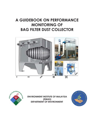
1. A GUIDEBOOK ON PERFORMANCE
MONITORING OF
BAG FILTER DUST COLLECTOR
ENVIRONMENT INSTITUTE OF MALAYSIA
(EiMAS)
DEPARTMENT OF ENVIRONMENT
2. A GUIDEBOOK ON
PERFORMANCE MONITORING OF
BAG FILTER DUST COLLECTOR
PUBLISHED BY :
ENVIRONMENT INSTITUTE OF MALAYSIA (EiMAS)
DEPARTMENT OF ENVIRONMENT
MINISTRY OF NATURAL RESOURCES AND ENVIRONMENT
UNIVERSITI KEBANGSAAN MALAYSIA CAMPUS
LOCKED BAG NO. 24, 43600, UKM BANGI
SELANGOR, MALAYSIA
TEL:+603-89261500 FAX:+603-89261700
WEBSITE:http://www.doe.gov.my/eimas
FIRST EDITION
SEPTEMBER, 2015
ISBN 978-983-42137-4-9
3.
4. i
TABLE OF CONTENTS
Title Page
Table Of Contents i
List Of Tables iii
List Of Figures iii
List Of Appendices iv
Foreword v
CHAPTER 1 - INTRODUCTION
1 Purpose of Guidebook 1
2 Advantages Performance Monitoring (PM) 2
2.1 Why PM? 2
2.2 PM On Bag Filter Dust Collector 2
3 Who Is Responsible For Conducting PM In
Industries
3
CHAPTER 2 – BAG FILTER DUST COLLECTOR
4 What Is Bag Filter Dust Collector? 4
4.1 Types Of Bag Filter Dust Collector 5
4.2 Components Of Bag Filter Dust
Control System
11
5 Equipment Associated With Bag Filter Dust
Collector (Pulse Jet)
13
6 General Operational Procedure Of Bag Filter
Dust Collector
15
5. ii
Title Page
CHAPTER 3 – PERFORMANCE MONITORING
7 Performance Monitoring Of Bag Filter Dust
Collector
15
7.1 Performance Monitoring Of Bag Filter Dust
Collector
15
7.2 Preventive Maintenance Of Bag Filter Dust
Collector
18
8 Measuring Instruments Used To Monitor Bag
Filter Dust Collector Performance
23
CHAPTER 4 – MAINSTREAMING OF BAG FILTER PERFORMANCE
MONITORING AGENDA
9 Record Keeping Requirement 29
10 Performance Monitoring Data Analysis and
Interpretation
29
11 Addressing Upset Conditions 32
12 Reporting and Performance Monitoring
Committee (PMC)
48
References 50
Appendices
6. iii
LIST OF TABLES
Table 1 Characteristics Of Filter Fabrics
Table 2 Comparison Of Bag Filter Dust Collector
Cleaning Types
Table 3 Typical Design Criteria Of Bag Filter
Table 4 Records Of Performance Data
Table 5 Performance Data And Measuring
Instrument
Table 6 Preventive Maintenance Of Bag Filter Dust
Collector
Table 7 List Of Problems, Possible Causes, Possible
Solution
LIST OF FIGURES
Figure 1 Main Components Of Bag Filter Dust
Control System
Figure 2 Equipment Associated With Bag Filter Dust
Collector (Pulse Jet)
Figure 3 Location Of Measuring Instruments To
Monitor Bag Filter Dust Collector
Performance
Figure 4 Example Of Monthly Trends Of
Performance Data
7. iv
LIST OF APPENDICES
Appendix 1 Typical Air To Cloth Ratios
Appendix 2 Typical Procedure Startup And Shutdown
Of Bag Filter Dust Collector
Appendix 3 Typical Form To Record Performance Data
Of Bag Filter Dust Collector
Appendix 4 Typical Form To Record Preventive
Maintenance Of Bag Filter Dust Collector
Appendix 5 General Form To Record Corrective Action
For Upset Conditions
Appendix 6 Example Of Monthly Bag Filter Performance
Monitoring Report To PMC
8. v
FOREWORD
Performance monitoring (PM) on air pollution control system (APCS) is
a legal requirement under Regulation 9(b), of the Clean Air
Regulations 2014 or in short, CAR. The PM is intended to ensure that
the APCS are monitored in a systematic manner so that its function is
always effective. In this regards, emphasis on preventive and
corrective action of the APCS hardware will warrant the emission from
APCS comply with emission standards of the regulations on a
continuous basis.
The practices of performance monitoring by industry will mainstream
environmental agenda into day to day tasks of the industry
management and instil self-regulation culture and pride of
environmental excellence and subsequently improves the industry’s
corporate image.
Thus, it is important for industry to have a good understanding on the
overall processes of the APCS. With this understanding, the industry will
also inculcate a sense of ownership and “do it right” in maintaining
the APCS operation by conducting monitoring of process parameters
at appropriate sampling locations and frequency. Hence, this
guidebook is useful as quick reference guide for conducting
performance monitoring of bag filter dust collector.
(DATO’ HALIMAH HASSAN)
Director General
Department of Environment, Malaysia
October 2015
9. vi
IMPORTANT NOTICE
This document is intended only as a quick reference/guide for
conducting performance monitoring of bag filters by the
industries. The Department of Environment assumes no
responsibility for the accuracy, adequacy, or completeness of
the concepts, methodologies, or protocols described in this
quick reference/guide book. Compliance with the regulatory
requirements and standards is solely the responsibility of the
industries
10. 1 | P a g e
CHAPTER 1 – INTRODUCTION
1. PURPOSE OF GUIDEBOOK
The main objectives of this guide book are:
a) As a quick reference/guide to interested
parties/industries in carrying out requirements of
conducting performance monitoring and
preventive maintenance requirement of a
pollution control system (bag filter) under the
Environmental Quality (Clean Air) Regulations 2014
(CAR 2014); and
b) To standardize procedures of performance
monitoring and preventive maintenance
requirement of a pollution control system (bag filter
dust collector) for easy inspection and reporting.
11. 2 | P a g e
2. ADVANTAGES OF PERFORMANCE MONITORING (PM)
a) Helps detect early onset of deteriorating
performance of the control system hence avoids
unnecessary plant shutdowns and costly
enforcement penalties;
b) Preventive maintenance procedure can specify
action levels at which corrective actions are to be
initiated; and
c) Act as acceptable surrogate to stack emission
testing to gage compliance with emission
standards.
2.1 Why PM?
a) Required by Regulation 9(b), of CAR (2014); and
b) All records shall be documented in standard
format and kept for inspection for 3 years.
2.2 PM on Bag Filter Dust Collector
a) For this guidance, discussion would focus more on
bag filter dust collector (type pulse jet).
b) For other type of bag filter dust collector the
operator/owner of the industries is responsible to
develop their own PM procedures with reference
to:
12. 3 | P a g e
(i) Key performance monitoring parameter for
the types of bag filter dust collectors
(ii) Sampling and monitoring frequency and
location of performance parameter.
(iii) Acceptable range of values for the
parameter for optimal bag filter dust collector
operation.
3 WHO IS RESPONSIBLE FOR CONDUCTING PM IN
INDUSTRIES
Each factories/premises is required under Section 49AA,
the Environmental Quality Act, 1974 to have a
competent person in charge of each air pollution
control system. The responsibilities of a competent
person is given as below:
a) Conduct and submit timely reports to DOE and PMC
as schedule/planned on:
i. performance monitoring (PM);
ii. preventive inspections; and
iii. changes to systems,
b) Maintain records of activities as above for a
minimum period of 3 years.
13. 4 | P a g e
c) Activate and supervise the running of Performance
Monitoring Committee (PMS).
d) Maintaining good working ethics and yearly status
level of Continuous Professional Development (CDP).
CHAPTER 2 – BAG FILTER DUST COLLECTOR
4 WHAT IS BAG FILTER DUST COLLECTOR ?
a) A bag filter dust collector unit generally consists of
one or more isolated compartments containing
rows of fabric bags in the form of round, flat, or
shaped tubes, or pleated cartridge.
b) These collectors use porous media to separate fine
dust particles from the airstream at efficiencies up
to 99.99 percent.
c) Table 1 lists those characteristics for some common
filter fabrics.
14. 5 | P a g e
4.1 Types of Bag Filter Dust Collector
a) Three (3) most common types of Bag Filter Dust
Collector based on cleaning mechanism of filter
bags:
Shaker Cleaning
Reverse-air Cleaning
Pulse-jet Cleaning
b) Table 2 lists the advantages and disadvantages
comparison of bag filter dust collector cleaning
types.
c) Table 3 summarizes typical design criteria for each
type of bag filter dust collector
15. 6 | P a g e
Table
1
:
Characteristics
of
Filter
Fabrics
16. 7 | P a g e
Table 2 : Comparison of Bag Filter Dust Collector Cleaning
Types
Types: Reverse-air baghouses
Advantages Disadvantages
Have high collection
efficiency for respirable
dust
Are preferred for high
temperatures due to
gentle cleaning action
Have low pressure drop for
equivalent collection
efficiencies
Have low air-to-cloth ratio
Require frequent cleaning
because of gentle cleaning
action
Have no effective way to
remove residual dust
buildup
Cleaning air must be filtered
Require personnel to enter
baghouse to replace bags,
which creates potential for
toxic dust exposure
17. 8 | P a g e
Types: Mechanical-shaker baghouses
Advantages Disadvantages
Have high collection
efficiency for respirable dust
Can use strong woven bags,
which can withstand
intensified cleaning cycle to
reduce residual dust buildup
Simple to operate
Have low pressure drop for
equivalent collection
efficiencies
Have low air-to-cloth ratio
Cannot be used in high
temperatures
Require large amounts of
space
Need large numbers of filter
bags
Consist of many moving
parts and require frequent
maintenance
Personnel must enter
baghouse to replace bags,
creating potential for
exposure to toxic dust
Can result in reduced
cleaning efficiency if even a
slight positive pressure exists
inside bag
18. 9 | P a g e
Types: Pulse-jet baghouses
Advantages Disadvantages
Have a high collection
efficiency for respirable dust
Have increased efficiency
and minimal residual dust
buildup due to aggressive
cleaning action
Can clean continuously
Can use strong woven bags
Have lower bag wear
Have small size and fewer
bags because of hgih air-to-
cloth ratio
Some designs allow bag
changing without entering
baghouse
Have low pressure drop for
equivalent collection
efficiencies
Require use of dry
compresses air
May not be used readily in
high temperatures unless
special fabrics are used
Cannot be used if high
moisture content or humidity
levels are present in the
exhaust gases
19. 10 | P a g e
Table 3 : Typical design criteria of bag filter
Type of bag
filter
Design variable Notes
Mechanical
Shaker
Air to cloth ratio :
0.3 to 2.4 m/min (optimum)
Filtration
velocity
(A/C ratio)
may refer to
Appendix 1
Pressure Drop :
2 – 6 in water (0.5 – 1.5 kPa)
Reverse Air Air to cloth ratio :
0.4 – 0.6 m min-1
Pressure Drop :
2 – 6 in water (0.5 – 1.5 kPa)
Pulse Jet Air to cloth ratio :
0.9 – 4.6 m min-1
Pressure Drop :
4 – 6 in water (0.5 – 1.5 kPa)
20. 11 | P a g e
4.2 Components of Bag Filter Dust Control System
a) A bag filter dust control system (Figure 1) usually
includes:-
Hoods or enclosure to capture the air
contaminant
Ductwork leading to an exhaust fan to
transport the contaminant
A bag filter dust collector unit, for removing the
dust particle contaminants from the air stream
Fan to create air flow in the system
Stack to discharge the clean air outside the
workplace or to the atmosphere
21. 12 | P a g e
Figure
1
:
Main
components
of
bag
filter
dust
control
system
22. 13 | P a g e
5 EQUIPMENT ASSOCIATED WITH BAG FILTER DUST
COLLECTOR (PULSE JET)
a) Important equipment associated with bag filter dust
collector (pulse jet):-
Air Compressor & dryer
Filter regulator
Air Tank
Pulsing valve
Electronic timer
Bag cage
Needlefelt or pleated bag filter
Dust Bin
Conveyour
Blow pipe
23. 14 | P a g e
Figure
2
:
Equipment
associated
with
bag
filter
dust
collector
(pulse
jet)
24. 15 | P a g e
6. GENERAL OPERATIONAL PROCEDURE OF BAG
FILTER DUST COLLECTOR
A typical procedure for initial start up, normal
start up and shutdown of bag filter dust
collector system are given in Appendix 2.
CHAPTER 3 – PERFORMANCE MONITORING
7. PERFORMANCE MONITORING OF BAG FILTER
DUST COLLECTOR
7.1 Performance Monitoring Of Bag Filter Dust
Collector
At the minimum the parameter stated in
Table 4 must be monitored and kept in log
book and made available to the DOE officers
for inspection. Typical forms to record
performance data on bag filter dust collectors
are depicted in Appendix 3.
25. 16 | P a g e
Table 4 : Records of Performance Data
Performance Data Comments
Pressure drop Pressure drop across the filter
must be monitored as an
indication of resistance to flow
and cleaning effectiveness
Flow rate Pressure drop information cannot
be interpreted properly unless
flow rate information is known.
Flow rate record is useful in
identifying a developing leak in
ducting or in the baghouse itself
Opacity Whether a continuous
transmissometer/ smoke meter/
opacity meter is incorporated
into the system or not, the output
on opacity / stack observation
should be recorded. The cause
of abnormal change in opacity
level should be pursued and
understood
Temperature In some applications,
temperature data is also
important to evaluate high
temperature excursion
26. 17 | P a g e
Performance Data Comments
condensation. At least the inlet
gas temperature of the
baghouse must be monitored.
Dust Additionally, at least one
parameter indicating the
quantity of dust removed (e.g.
weight or volume) from each
compartment of the baghouse
must be monitored. Significant
change in dust quantity may be
indicative of baghouse failure or
of process change
Compressed air
pressure
Where cleaning is effected by
using compressed air pressure
should be monitored to ensure
effective cleaning operation
There are also other monitored data should be
considered to ensure effective dust collector
system such as fan current, fan rpm
27. 18 | P a g e
7.2 Preventive Maintenance Of Bag Filter Dust
Collector
Table 5 summarizes frequency of preventive
maintenance of bag filter dust collector. The
industry should abide to this procedure on
preventive maintenance of the bag filter dust
collector. The record keeping of preventive
maintenance on bag filter dust collector is
given Appendix 4
28. 19 | P a g e
Table 5 : Preventive maintenance of bag filter dust
collector
Frequency
Procedure
Daily
Check pressure drop
Observe stack (visually or with opacity
meter)
Walk through system, listening for proper
operation
Check for unusual occurrences in process
Observe control panel indicators
Check compressed-air pressure
Assure that dust is being removed from
system
29. 20 | P a g e
Frequency
Procedure
Weekly
Inspect screw-conveyor bearings for
lubrication
Check packing glands
Operate damper valves
Check compressed-air lines, including line
filters and dryers
Check that valves are opening and closing
properly in bag-cleaning sequence.
Verify accuracy of temperature-indicating
equipment
Check pressure-drop-indicating equipment
for plugged lines
30. 21 | P a g e
Frequency
Procedure
Monthly
Check all moving parts in shaker
mechanism
Inspect fans for corrosion and material
buildup
Check drive belts for wear and tension
Inspect and lubricate appropriate items
Spot-check bag tension
Spot check for bag leaks
Check hoses and clamps
Check accuracy of indicating equipment
Inspect housing for corrosion
31. 22 | P a g e
Frequency
Procedure
Quaterly
Inspect baffle plate for wear
Inspect bags thoroughly
Check duct for dust buildup
Observe damper valves for proper seating
Check gaskets on doors
Inspect paint, insulation, etc.
Check screw conveyor for wear or
abrasion
Check fan belts
Annually
Check welds
Inspect hopper for wear
32. 23 | P a g e
8. MEASURING INSTRUMENTS USED TO MONITOR
BAG FILTER DUST COLLECTOR PERFORMANCE
a) A monitoring system must be properly
installed and maintained to provide
reliable data.
b) Figure 3 illustrate the location of measuring
instruments to monitor bag filter
performance.
c) In the majority of bag filter operation,
measuring instruments is installed directly
on the air pollution control equipment, and
there are also a premise had installing and
connecting directly to a programmable
logic controller (PLC). However there is a
need to provide portable measuring
instruments for the purpose of verifying the
data recorded by automatic system.
d) Table 6 summarise the measuring
instruments to monitor bag filter dust
collector performance variables.
33. 24 | P a g e
Figure
3
:
Location
Of
Measuring
Instruments
To
Monitor
Bag
Filter
Dust
Collector
Performance
34. 25 | P a g e
Table 6 : Performance Data and Measuring
Instrument
Label
(measuring
location refer
to Figure 3)
Performance
Data
(Unit)
Example of Measuring
Equipment
Pressure drop
across bag
filter body
(mm WG or
inch WG)
Magnehelic gauge
U tube manometer
35. 26 | P a g e
Label
(measuring
location refer
to Figure 3)
Performance
Data
(Unit)
Example of Measuring
Equipment
Air flow rate
(m3/hour) Pitot tube and flow
meter (portable)
Flow meter
36. 27 | P a g e
Label
(measuring
location refer
to Figure 3)
Performance
Data
(Unit)
Example of Measuring
Equipment
Temperature
(Degree C)
Thermometer
Opacity
Opacity Meter
37. 28 | P a g e
Label
(measuring
location refer
to Figure 3)
Performance
Data
(Unit)
Example of Measuring
Equipment
Compress air
pressure (bar)
Filter regulator
Fan Running
Ampere
(A)
Clamp meter (portable)
Ammeter for fan at
control panel
38. 29 | P a g e
CHAPTER 4 – MAINSTREAMING OF BAG FILTER
PERFORMANCE MONITORING AGENDA
9. RECORD KEEPING REQUIREMENT
a) Regulation 10, of the Clean Air Regulations
(2014) requires premises to maintain a
record of production process, preventive
maintenance and performance
monitoring of air pollution control system.
b) A record should be kept at least 3 years
and be made available for inspection.
10. PERFORMANCE MONITORING DATA ANALYSIS
AND INTERPRETATION
a) Advantages of data analysis:-
able to provide a very good
indication of the performance of a
dust collector.
able to aid in the detection of
component deterioration in the bag
filter system.
39. 30 | P a g e
b) The performance daily data (pressure,
temperature, air flow rate, compressed air
pressure, opacity etc.) must be plotted into
a graph trends and compare with the
maximum and minimum operating limits for
dust collector.
c) The analysis information must be provided
on a monthly basis and reported to the
Performance Monitoring Committee.
40. 31 | P a g e
Figure
4
:
Example
of
Monthly
Trends
of
Performance
Data
41. 32 | P a g e
11. ADDRESSING UPSET CONDITIONS
a) Any upset situation based on the daily
performance monitoring data recorded or
malfunction of air pollution control system
must be attended to immediately. The
corrective actions taken should be
recorded in the relevant form as illustrated
in Appendix 5.
b) For reference Table 7 indicates the
common troubleshooting problem
associated with the operation condition of
the bag filter dust collector.
42. 33 | P a g e
Table 7 : Troubleshooting - List of problems, possible
causes, possible solution
PROBLEM POSSIBLE CAUSE POSSIBLE SOLUTION
1. High
Pressure
Drop
a) In-
appropriate
air-to-cloth
ratio
Check table of
representative air-to-
cloth ratio values and for
the recommendations of
the dust collector or filter
manufacturer
Close some branches of
the ducting system,
remove part of the
attached load
Improve hood designs to
allow lowering flow
requirements
Adjust fan/blower
damper or slide gates
b) Plugged
filter media
End of filter life – replace
Excess loading – add
pre-cleaner, operate
filter cleaning system
with reduced or no
airflow (downtime
cleaning)
43. 34 | P a g e
PROBLEM POSSIBLE CAUSE POSSIBLE SOLUTION
Wet, agglomerative,
sticky, hygroscopic dusts
– change filter to
appropriate design and
material
Oily air stream – difficult
to remedy; pre-coating
absorbent material such
as lime powder may
extend life
Wet or oil compressed
air – see below
c) Incorrect
choice of
filter media
or surface
treatment
Work with collector or
filter supplier to
determine best choices
of filter media to meet
system needs
d) Wet filter
media
Eliminate source of
water, check for dust
collector body rain leaks,
check spark
extinguishing system,
check for water in
compressed air
44. 35 | P a g e
PROBLEM POSSIBLE CAUSE POSSIBLE SOLUTION
Eliminate dew point
excursions, and use start-
up and shutdown
procedures to dry filter
media
e) Cleaning
mechanism
not working
Check electrical,
mechanical and/or
pneumatic systems for
correct operation and
replace or repair as
needed
f) Loss of
compressed
air and/or
low pressure
Monitor compressed air
and ensure adequate
volume and pressure for
all shifts the dust
collector operates.
Increase compressed air
line size or install
dedicated compressor
Malfunction of solenoid
or diaphragm valve may
be allowing continuous
air loss
45. 36 | P a g e
PROBLEM POSSIBLE CAUSE POSSIBLE SOLUTION
g) Wet or oily
compressed
air
Add filter or dryer to
system, or service
existing system
Reduce dew point to
less than lowest
expected operating
temperature
h) Pulse pipes
missing,
installed
upside
down, or not
properly
aligned with
filters
Check mechanical
system for proper
installation and
alignment
i) Dust storage
full or
plugged
Service dust storage or
take-away system on
regular schedule. Do not
use dust collector
hopper for dust storage
j) Instrument
error
Check for dust-filled,
plugged, kinked,
cracked, crushed or
missing pneumatic lines
46. 37 | P a g e
PROBLEM POSSIBLE CAUSE POSSIBLE SOLUTION
Check all fittings for leaks
Check gauge for
evidence of dust
contamination
Check for mechanical or
electrical instrument
failure
Check gauge
calibration
2. Low
Efficiency
a) Air-to-cloth
ratio too
high
Check table of
representative air-to-
cloth ratio values and for
the recommendation of
the dust collector or filter
manufacturer
Close some branches of
the ducting system
Improve hood designs to
allow lowering flow
requirements
Adjust fan/blower
damper or slide gates
47. 38 | P a g e
PROBLEM POSSIBLE CAUSE POSSIBLE SOLUTION
b) Damaged
filter media
Check for mechanical
damage of filters, tears,
split seams, damage
due to bag away
impact with other bags
or dust collector body,
installation damage,
bend or dented end
caps or liners
Test with fluorescent
powder & light and
replace if filter damaged
c) Improper
filter
installation
Check installation
information. Look for
airflow directional arrows
on filters. Look for
gasketed filters installed
backwards
d) Loose filter
retention
Check band clamps,
cranks, hand knobs, bolt
downs, snap bands, or
other filter mechanisms
for proper tightness.
Tighten as directed by
installation instructions
48. 39 | P a g e
PROBLEM POSSIBLE CAUSE POSSIBLE SOLUTION
Test with fluorescent
powder & light (repair)
e) Damaged
or missing
filter
gaskets
Check for gaskets that
are torn or detached
f) Tube sheet
leaks
Check for cracks, broken
welds, or missing
fasteners
Test with fluorescent
powder & light
g) Warped
tube sheets
Test flatness of tube
sheet; look for leaks at
filter gasket areas.
Common problem after
fires
Test with fluorescent
powder & light
h) Missing
filters
Check all filters. Install
any that are missing
49. 40 | P a g e
PROBLEM POSSIBLE CAUSE POSSIBLE SOLUTION
i) Abrasion of
filter media
High velocity inside dust
collector, unequal air
distribution, duct
directional changes
close to dust collector
inlet, high solids loading,
solids collection
container full or plugged
Add pre-cleaner or
abrasion reduction inlet
box. Redesign inlets to
lower velocities. Remove
elbows too close to dust
collector inlet. Service
solids collection
containers on regular
schedule
j) Fire-
damaged
filters
Look for filters with burn
holes or for missing filter
media.
Replace any damaged
filters. Eliminate all
sources of ignition or
burning embers. Add
spark and fire
suppression system
50. 41 | P a g e
PROBLEM POSSIBLE CAUSE POSSIBLE SOLUTION
k) Excessive
cleaning
frequency
Over-cleaning filters
reduces efficiency
Install pressure drop
based cleaning control.
Reduce frequency of
cleaning
l) Excessive
cleaning
energy
Check operating
instructions, regulate
cleaning air pressure at
dust collector
manufacturer's
recommendation value
m) Chemical
attack
Check the chemical
compatibility of the
solids and entrained
vapors with the filter
media. May be affected
by concentration and
temperature. Choose
filter media suited to
application
51. 42 | P a g e
PROBLEM POSSIBLE CAUSE POSSIBLE SOLUTION
n) Temperature Measure air stream
temperature and
compare to filter media
rating. Install filter with
proper temperature
rating
3. Premature
Filter
Failure
a) Air-to-cloth
ratio too high
Check table of
representative air-to-
cloth ratio values and for
the recommendation of
the dust collector or filter
manufacturer
Close some branches of
the ducting system
Improve hood designs to
allow lowering flow
requirements
Adjust fan/blower
damper
b) Abrasion of
filter media
High velocity inside dust
collector, unequal air
distribution, duct
directional changes
close to dust collector
inlet, high solids loading,
52. 43 | P a g e
PROBLEM POSSIBLE CAUSE POSSIBLE SOLUTION
solids collection
container full or plugged
Add precleaner or
abrasion reduction inlet
box. Redesign inlets to
lower velocities. Remove
elbows too close to dust
collector inlet. Service
solids collection
containers on regular
schedule
c) Chemical
attack
Check the chemical
compatibility of the
solids and entrained
vapors with the filter
media. May be affected
by concentration and
temperature. Choose
filter media suited to
application
d) Temperature Measure air stream
temperature and
compare to filter media
rating. Install filter with
proper temperature
rating
53. 44 | P a g e
PROBLEM POSSIBLE CAUSE POSSIBLE SOLUTION
e) Incorrect
choice of
filter media
or surface
treatment
Work with dust collector
or filter supplier to
determine best choices
of filter media to meet
system needs
f) Wet or oily
compresse
d air
Add filter or dryer to
system, or service
existing system
Reduce dew point to
less than lowest
expected operating
temperature
g) Dust
storage full
or plugged
Service dust storage or
take-away system on
regular schedule. Do not
use dust collector
hopper for dust storage
h) Oily
airstream
Difficult to remedy;
precoating with
absorbent material such
as lime powder may
extend life
54. 45 | P a g e
PROBLEM POSSIBLE CAUSE POSSIBLE SOLUTION
4. In-
sufficient
Air Flow
a) Blower
rotating
backward
Check rotation arrows
on blower housing.
Change rotation if
necessary
b) Blower
malfunction
Eroded fan wheel,
misadjusted – adjusted
inlet cone, slipping drive
belt
Repair or replace as
required
c) Dust
collector or
ducting
openings
not closed
Look for hopper
discharges, inspection
doors, access doors,
unused duct branches
open. Close off any
unnecessary openings
on both clean and dirty
side of dust collector
and in ductwork
d) Ducting
collapsed
or plugged
Check all affected
portions of system for
plugged ducting
e) Improper
duct design
Have knowledgeable
person check duct
design for proper static
55. 46 | P a g e
PROBLEM POSSIBLE CAUSE POSSIBLE SOLUTION
and flow balance and
duct design
f) Excess
flexible
ducting
Flexible duct requires
more static pressure due
to irregular interior
surface and direction
changes. Calculate
losses, increase duct
diameter, increase static
availability, or reduce
length of run
g) Improper
transitions or
elbows
Check for transitions
facing into flow rather
than with flow
Use minimum angle
between trunk line and
branch inlet
Use long radius elbows
h) Blast-
gate/Damp
er settings
Check all blast
gates/damper for
proper settings
Re-adjust any set out of
tolerance
56. 47 | P a g e
PROBLEM POSSIBLE CAUSE POSSIBLE SOLUTION
i) Blower
system
effects
Elbows close to blower
inlet, improper inlet box
without turning vanes,
improperly designed or
no-discharge duct,
directional change close
to elbow discharge,
improper rain hood.
Consult trained duct
designer or blower
supplier, correct ducting
errors. Speed up blower
j) Blower inlet
or exhaust
dampers
Check settings of all flow
dampers in system
k) Blower motor
speed
Check with blower
supplier to ensure blower
and motor speeds are
compatible
l) High pressure
drop
Any fault that cause high
pressure drop can also
cause low airflow
57. 48 | P a g e
12. REPORTING AND PERFORMANCE MONITORING
COMMITTEE (PMC)
a) There must be a formal and permanent
committee established wthin the industry to
monitor the bag filter performance on a
continuous basis. This committee is
commonly known as the performance
monitoring committee (PMC). The members
of PMC should comprise senior
management personnel of the industry from
various relevant departments.
b) Through this committee the results of the
performance monitoring activities are
presented, reviewed and discussed. Monthly
trends of performance data plotted in graph
and corrective action taken should be
presented to committee for improvement
discussion.
c) Key industrial personnel from relevant
departments are directly involved in bag
filter operation issues are jointly responsible
for ensuring regulatory compliance so that
58. 49 | P a g e
the company business plans can progress
without hitches due to noncompliance issue.
d) The record date of the meeting and the
reports presented to the committee shall be
kept for inspection by DOE. The conduct of
PMC meetings is mandatory for CePBFO to
maintain their registration with the DOE in the
National Registry of Certifed Environmental
Professionals (NRCEP).
e) Example of monthly status report of bag filter
performance monitoring for PMC meeting is
given in Appendix 6
59. 50 | P a g e
REFERENCES
1. Margaret Pernce. 2012. Handbook of Air
Pollution Control Systems and Devices. Delhi;
University Publications
2. American Conference of Governmental
Hygienists. 1992. Industrial Ventilation A Manual
of Recommended Practice. 21st Ed. Cincinnati,
OH; ACGHI
3. C. David Cooper & F.C Alley. 2011. Air Pollution
Control – A Design Approach. 4th Ed. Long
Grove, Illinois; Waveland Press Inc.
4. David S. Beachler, Jerry Joseph, Mick Pomelia
1995. Fabric Filter Operation Review – APTI
Course SI:412A. 2nd Ed. N. Carolina State
University
5. Department of Environment Malaysia. 2006.
Technical Guidance On Performance
Monitoring Of Air Pollution Control Systems.
6. Department of Environment Malaysia. 2014.
Course Module on Certified Environmental
Professional In Bag Filter Operation; CePBFO,
EiMAS
61. APPENDIX 2
INITIAL START-UP
Visually inspect all equipment and remove all foreign
material and trash. Check that all guards and safety
equipment are installed. Be sure all electric wiring has been
checked out.
1. One by one, start up of the fan, discharge valves,
and conveyors, and any other accessory equipment.
Check each one for proper rotation, speed, and
operation. Turn each one off and correct problems if
necessary, then recheck.
2. Check that all ductwork connections and support are
in place and tight, clean-out ports are closed, every
duct is free of debris, hoods are in place and free of
contact with machinery, and the fan exhaust is free
and clear and aimed correctly.
3. With all equipment turned off, check that all doors
and ports are closed on the collector.
4. Turn on the compressed air to the collector cleaning
system and check for the leaks. If air is leaking from
any blowpipe, there may be a leak in the diaphragm
to solenoid valve tubing line. Turn off the compressed
air when everything checks out.
5. Turn on the electric power to the timer or control
panel. The red power on light should come on. Select
62. APPENDIX 2
the timer position for cleaning, and turn both the off
time and the on time knobs to a fully
counterclockwise position. The individual timing lights
at the output terminals should blink at 1.5-s intervals,
and the corresponding solenoid valves should
activate audibly.
6. Turn on the air supply to the air header. Set the air
supply pressure regulatory to about 5~6 bar, unless
otherwise instructed. Each diaphragm and solenoid
valve should operate every 1.5s (exhaust air can be
felt and heard exhausting from each valve). Let the
collector pulse for about 10 minutes to ensure that all
lines are clear. Then set the off time to about 20~30s.
These settings may need later adjustment in
operation.
7. Turn on all dust discharge equipment.
8. If moisture or condensible vapors are present in the
air stream, the operating temperature should be
brought up above that dew point. It may take some
time to get all the ductwork and collector walls
above the dew point.
9. Start the fan with the damper set for about half flow
volume and run for about 30 minute; then start
introducing a light load of dust or an intended pre
63. APPENDIX 2
coat filter aid powder or absorbent. This is particularly
recommended when the process dust will be a very
fine particle size, and some pre coat dust cake is
critical.
10. Observe the differential pressure reading on the
photohelic or magnehelic gauge. The pressure drop
should be very low at start-up. After some 30 minutes
of operation with light incoming dust load, the
pressure differential should begin to climb as the bags
acquire some coating. The filtration efficiency should
then be high enough to begin the feeding step
below.
11. The fan damper can be opened up, gradually, and
then dust fed at normal design operating rates. The
differential pressure should then climb for several
hours and stabilize at some value between 1 and 6 in
Wg. If below 4 in Wg, then gradually increase the off-
time until it reaches 4 in Wg. This is a general guide,
but use caution on fragile filter media and with very
fine dust.
12. Temperature must be controlled to remain below the
maximum rating of the filter bags or cartridges.
13. The collector should now ready for regular operation
at the design capacity.
64. APPENDIX 2
NORMAL DUST COLLECTOR START-UP
Subsequent start-ups should begin with all system off (if new
filter bags have just been installed, then the initial start-up
procedure above should be followed). Normally equipment
should be turned on as follows:
1. All ports, doors, and rotating discharge equipment
should be closed, and all safety devices should be in
place.
2. Turn on the compressed air.
3. After the pressure reaches 5~6 bar or the normal
level, turn on the timer.
4. Turn on all dust discharge equipment.
5. Preheat the system if necessary (this may precede
the other steps if several hours preheat is required).
6. Turn on the fan and introduce filter aid powder or a
low loading of process dust to precoat, then
increase dust flow to the normal operating load.
7. If the exhaust is visible, then refer to the
troubleshooting guide. A collection efficiency of
around 99-95 percent should eliminate any visible
plume unless some steam, vapor or SO2 is present.
65. APPENDIX 2
NORMAL DUST COLLECTOR SHUT-DOWN
1. For dust collection system, the shutdown generally
reverses the start-up. First turn off the process dust
feed, then the fan, unless the two operate in an
integrate manner. Wait 5 to 10 minutes and then turn
off the cleaning timer to allow filter cleaning without
input dust. Then turn off the compressed air supply,
and finally the discharge equipment can be
stopped.
2. Process systems. Process dryers and equipment
feeding the collector should be run until empty of
dust, and if moisture is present, then the heat and
fan flow at a reduced rate should be maintained
until the collector metal and filter bags are dry. Then
proceed as in step 1.
66. APPENDIX 2
SAFETY BEFORE ENTERING DUST COLLECTOR
1. Run cleaning system for about 10 minutes with the
fan off to clean the filters well.
2. Run solids out of the hopper discharge equipment
during this clean out and inspect for amount of dust
and condition.
3. Turn off and lock out all electric power to rotating
equipment.
4. If toxic gases are present, purge all collector and
block off inlet duct or damper, and follow any further
safety precautions.
5. Install safety cables and catwalks where needed.
6. Secure access doors in an open position, or remove
odors, unless rain or ambient temperature intrusion is
undesirable, to prevent trapping anyone inside.
7. Use the buddy system and other safety precautions
when people must enter the bag house.
8. Wear respirator if needed in the bag house,
especially if carcinogenic dust or toxic vapors are
present.
9. Use common sense and any special precautions.
67. APPENDIX 3
TYPICAL FORM TO RECORD PERFORMANCE DATA/ACTIVITIES
OF BAG FILTER DUST COLLECTOR
(A) Daily; Month: …………………
Date
Filter
Pressure
drop
(mmWG)
Flow
rate
(m3/hour)
Opacity
or
Stack
emission
condition
Discharge
Hopper
Condition
Temperature
(degC)
Compressed
Air
Pressure
(bar)
Operator
Signature
Supervisor
Signature
1
2
3
4
5
6
7
8
..
30
Operating/Control Setting Minimum Maximum
Pressure Drop
Temperature
Flow Rate
Compressed Air Pressure
Timer Ontime =
Offtime =
68. APPENDIX 4
TYPICAL FORM TO RECORD PERFORMANCE DATA OF BAG
FILTER DUST COLLECTOR (PREVENTIVE MAINTENANCE)
B) DAILY
Month : _______________ Year : _______________
Procedure
Notes
Entries by
Operator
Checked by
Supervisor
Name
Sign
Date
Name
Sign
Date
1. Walk through
system, listening for
proper operation
2. Check for unusual
occurrences in
process
3. Observe control
panel indicators
4. Ensure that dust is
being removed
from system
69. APPENDIX 4
(C) WEEKLY
Month : _______________ Year : _______________
Procedure
Notes
Entries by
Operator
Checked by
Supervisor
Name
Sign
Date
Name
Sign
Date
1. Inspect screw conveyor
bearings for lubrication
2. Check packing glands
3. Check damper / valves
for proper setting
4. Check compressed air
lines, including line filters
and dryers
5. Check the valves are
opening and closing
properly in bag cleaning
sequence
6. Check temperature –
indicating equipment
7. Check pressure drop
indicating equipment for
plugged lines
70. APPENDIX 4
(C) MONTHLY
Month : _______________ Year : _______________
Procedure
Notes
Entries by
Operator
Checked by
Supervisor
Name
Sign
Date
Name
Sign
Date
1. Inspect fan for
material build up and
corrosion
2. Check drive belts for
wear and tension
3. Inspect and lubricate
appropriate items
4. Spot check for bag
leaks
5. Check hoses and
clamps
6. Check accuracy of
indicating equipment
7. Inspect housing for
corrosion
71. APPENDIX 5
GENERAL FORM TO RECORD CORRECTIVE ACTION FOR
UPSET CONDITIONS
(Applicable for all types of control equipment)
Month : __________
Date
Type of
Upset
Condition
Diagnosis
of Cause
of Upset
Condition
Any Non
Compliance
of Discharge
Standard
Occurred –
Give
Explanation
Corrective
Action
Taken
When
Condition
Returned
to Normal
Name
and
Signature
of
Reporting
Officer
Name
and
Signature
of
Supervisor
72. APPENDIX 6
EXAMPLE
BAG FILTER PERFORMANCE MONITORING REPORT
MONTH : MAC 2014
BAG FILTER DUST COLLECTOR ID : BF07
Pressure Drop
Flow Rate
Summary
1) Pressure drop across limit/lower air flow rate start 12/3/2014 – finding filter
bag choked. Replacement done on 17/3/2014 and bag filter running back on
acceptable ranges.
2) Others corrective action taken for month Mac as per attached
Report prepared by:
Signature :……………………………………
Name of Competent Person : ……………………………………….
73. CONVERSION FACTORS
Mass 1 kg 2.205 lb
1 lb 0.4536 kg
1 tonne 0.9842 tons
1 ton 1.016 tonnes
Length 1 mm 0.03937 in
1 in 25.4 mm
1 m 3.281 ft
1 ft 0.3048 m
1 m 1.094 yd
1 yd 0.9144 m
Area 1 mm2 0.00153 in2
1 in2 645.2 mm2
1 m2 10.764 ft2
1 ft2 0.0929 m2
1 m2 1.196 yd2
1 yd2 0.8361 m2
Volume 1 mm3 0.000061 in3
1 in3 16 390 mm3
1 m3 35.32 ft3
1 ft3 0.0283 m3
1 m3 1.308 yd3
1 yd3 0.7646 m3
Density 1 kg/m3 0.06242 lb/ft3
1 lb/ft3 16.02 kg/m3
1 tonne/m3 0.7524 ton/yd3
1 ton/yd3 1.329 tonne/m3
74. Pressure 1mm WG 9.81 Pascal
1 inch WG 249.17 Pascal
1 mbar 100 Pascal
1mbar 0.1 kPa
1 mm HG 133.3 Pascal
1 PSI 6894.75 Pascal
USEFUL FORMULA
1) Q = A x V x 3600
Where Q = flow rate (m3/hour)
A = area (m2)
V = velocity (m/s)
2) A = π D2
4
where A = area (m2)
π = 3.142
D = diameter (m)
3) P = πD ,
where P = perimeter (m)
π = 3.142
D = diameter (m)
75. DOE STATES
IBU PEJABAT JABATAN ALAM SEKITAR
KEMENTERIAN SUMBER ASLI DAN ALAM SEKITAR
ARAS 1-4, PODIUM 3, WISMA SUMBER ASLI
NO. 25, PERSIARAN PERDANA, PRESINT 4
62574 PUTRAJAYA
JABATAN ALAM SEKITAR NEGERI MELAKA
ARAS 19 MENARA PERSEKUTUAN
JALAN PERSEKUTUAN
BANDAR MITC HANG TUAH JAYA
75450 AYER KEROH
JABATAN ALAM SEKITAR NEGERI PAHANG
ARAS 1, KOMPLEKS MAHKAMAH KUANTAN
BANDAR INDERA MAHKOTA
25200 KUANTAN
JABATAN ALAM SEKITAR NEGERI SEMBILAN
TINGKAT 5, ARAB MALAYSIAN BUSINESS CENTRE
JALAN PASAR
70200 SEREMBAN
JABATAN ALAM SEKITAR W.P. KUALA LUMPUR
TINGKAT 1 & 2, WISMA SCA
NO.3 BATU 2, JALAN SUNGAI BESI
57100 KUALA LUMPUR
76. JABATAN ALAM SEKITAR NEGERI PERAK
TINGKAT 7 & 9, BANGUNAN SERI KINTA
JALAN SULTAN IDRIS SHAH
30000 IPOH
JABATAN ALAM SEKITAR NEGERI PULAU PINANG
ARAS BAWAH – ZON B
WISMA PERSEKUTUAN
SEBERANG PERAI UTARA
13200 KEPALA BATAS
JABATAN ALAM SEKITAR NEGERI SELANGOR
TINGKAT 12, 13, & 14 SUNWAYMAS
JALAN TENGKU AMPUAN ZABEDAH C 9/C, SEKSYEN 9
40100 SHAH ALAM
JABATAN ALAM SEKITAR NEGERI KEDAH
ARAS 2, MENARA ZAKAT
JALAN TELOK WAN JAH
05200 ALOR SETAR
JABATAN ALAM SEKITAR NEGERI JOHOR
WISMA JAS JOHOR
NO. 46, JALAN PERTAMA, TOWER 2
PUSAT PERDAGANGAN DANGA UTAMA
81300 JOHOR BAHRU
77. JABATAN ALAM SEKITAR NEGERI KELANTAN
LOT 322 - 324, SEKSYEN 27
JALAN SRI CEMERLANG
15300 KOTA BHARU
JABATAN ALAM SEKITAR NEGERI TERENGGANU
WISMA ALAM SEKITAR
OFF JALAN SULTAN OMAR
20300 KUALA TERENGGANU
JABATAN ALAM SEKITAR NEGERI PERLIS
TINGKAT 2, BANGUNAN KWSP
JALAN BUKIT LAGI
01000 KANGAR
JABATAN ALAM SEKITAR NEGERI SARAWAK
TINGKAT 7-9, WISMA STA NO. 26,
JALAN DATUK ABANG ABDUL RAHIM
93450 KUCHING
JABATAN ALAM SEKITAR NEGERI SABAH
ARAS 4, BLOK A KOMPLEKS PENTADBIRAN KERAJAAN
PERSEKUTUAN SABAH
JALAN UMS-SULAMAN, LIKAS
88450 KOTA KINABALU