Orifice Plates
•
0 j'aime•1,857 vues

Orifice Plate In Thane, Mumbai, India, Flow Meter In Thane, Mumbai, India

Recommandé
Contenu connexe
Tendances
Tendances (20)
En vedette
En vedette (20)
Similaire à Orifice Plates
Similaire à Orifice Plates (20)
Plus de NK Instruments Pvt. Ltd.
Plus de NK Instruments Pvt. Ltd. (20)
Dernier
Dernier (20)
Orifice Plates
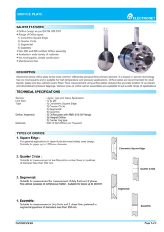
- 1. Page 1 of 4CAT/ORIFICE-R1 ● Orifice Design as per BS EN ISO 5167 ● Range of Orifice types 1) Concentric Square Edge 2) Quarter Circle 3) Segmental 4) Eccentric ● Non IBR and IBR certified Orifice assembly ● Available in wide variety of materials ● No moving parts, simple construction ● Maintenance-free ORIFICE PLATE ELECTRONET SALIENT FEATURES DESCRIPTION Electronet series orifice plate is the most common differential pressure flow primary element. It is based on proven technology has no moving parts and is suitable for high temperature and pressure applications. Orifice plates are recommended for clean liquids, gases and low velocity steam flows. Flow measurement using orifice plates requires the accurate location of up stream and downstream pressure tappings. Various types of orifice carrier assemblies are available to suit a wide range of applications TECHNICAL SPECIFICATIONS Service : Liquid, Gas and Vapor Application Line Size : ½” to 20” Type : 1) Concentric Square Edge 2) Quarter Circle 3) Segmental 4) Eccentric Orifice Assembly : 1) Orifice plate with ANSI B16.36 Flange 2) Integral Orifice. 3) Carrier ring type Materials : SS316 Std.(Others on Request) TYPES OF ORIFICE 1. Square Edge : For general applications in clean fluids-the most widely used design. Suitable for pipes up to 1000 mm diameter 2. :Quarter Circle Suitable for measurement of low Reynolds number flows in pipelines of diameter less than 750 mm. 3. Segmental: Suitable for measurement for measurement of dirty fluids and 2 phase flow-allows passage of extraneous matter . Suitable for pipes up to 350mm 4. Eccentric: Suitable for measurement of dirty fluids and 2 phase flow, preferred to segmental pipelines of diameters less than 350 mm. Concentric Square Edge Quarter Circle Segmental Eccentric
- 2. ORIFICE MATERIAL Page 2 of 4 ● 316 Stainless Steel ● Hastelloy® C276 ● Hastelloy® B3 ● Monel® 400 ● Titanium ● Tantalum ● PTFE and PVDF . DIMENSIONAL DETAILS The outside diameter of the orifice plate is equal to the bolt circle diameter of the connecting flanges minus the diameter of the bolt. This ensures that the plate is centered accurately in the line. Plate thicknesses depend on line size and differential pressure, and is sufficient to prevent the plate from bending under operating conditions. Orifice plates can be made in accordance with customer drawings as required. CAT/ORIFICE-R1
- 3. ANSI B 16.36 ORIFICE FLANGES Page 2 of 4CAT/ORIFICE-R1 Orifice flanges are intended for use instead of standard pipe flanges when an orifice plate or flow nozzle must be installed. Pairs of pressure tappings are machined into the orifice flange, making separate orifice carriers or tappings in the pipe wall unnecessary . The range of orifice flanges covers all standard sizes and ranges, and all common flange materials. Flanges are available in socket weld or weld neck form, and are typically supplied with two ½” NPT tappings in each flange. Jacking screws to ensure ease of removal of the primary flow element are provided. Orifice flanges are supplied complete with bolting and gasket kits. INTEGRAL ORIFICE ANSI B 16.36 ORIFICE FLANGE ASSEMBLY Typically consisting of a factory assembled section of pipe with an orifice plate mounted between two flanges near the center of the run, terminated with a flange at each end to connect to the process. Building the assembly in the factory allows us to control all the variables which can lead to inaccuracies which can arise if the system is assembled by untrained personnel on-site. Other advantages include reduced installation time; the completed section only needs to be bolted into the pre-prepared line. The complete assembly can be calibrated to provide the maximum accuracy . INTEGRAL ORIFICE PLATE ASSEMBLY IMPULSE PIPING FOR ORIFICE
- 4. NK Instruments Pvt. Ltd.B-501/504, 5th floor, Raunak Arcade, Near THC Hospital, Gokhale Road, Naupada, Thane(W) 400602. Maharashtra INDIA Telefax Nos.: 91-22-25301330 / 31 / 32 E-Mail: sales@nkinstruments.com Web: http://www.nkinstruments.com Skype: nitinkelkarskype Gtalk: nkinstruments2006 Page 4 of 4 TECHNICAL INFORMATION REQUIRED CAT/ORIFICE-R1 Line Size Type Material Tap Location IBR Certification Concentric Square Edge SS 316 Flange No SS 304 Corner Yes Other (Pl Specify) Other - D&D/2 Quarter Circle Segmental Eccentric Orifice Details Other (Pl Specify) Process Data Accessories Service Flow Unit Flow Rate Pressure Temperature Density Viscosity Base Temp. Condensing Pot Impulse Tubing Isolation valves Nipples Base Pressure Liquid Required Required _______________ Mtrs. Required Required Not Required Not Required Not Required Not Required 3 M/h Max.________ Max.________ Max.________ @ 20~C______ @ Flowing Condition_______________ ___________~C (For GAS / Vapor) 2 ___________ Kg/Cm (For GAS / Vapor) Gas Kg/s Min._________ @Flowing Condition_________ Steam TPH Nor._________ 900 LB Others Others ASTM A182 F304 Stainless Steel ASTM A320 L7 and ASTM A194 Gr 4 or 7 Required Type Orifice Assembly Flange Rating Material Connection Studbolt & Nut Yes Flange 150 LB ASTM A182 F316 Stainless Steel Socket Weld ASTM A193 B7 and ASTM A194 Gr 2H No Integral 300 LB Weld neck 600 LB Other (Pl Specify) ________