1. 500-5E0 500-5E0
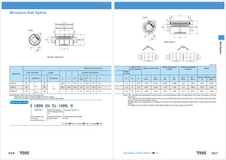
Miniature Ball Spline L
2-φ d0 C C
C C
d5
L2
(Overall length with two seals)
L φD
D0
(Overall length without two seals)
2-φ d0 L3
C
C
d5
b
l0
t
D0 φ D2 φ D 30°
Model LBS10
Ball Spline
M A.1 M A.2
b
l0
t
30°
Models LBS6 and 8
Unit: mm
Spline shaft Basic load rating Static permissible
Spline nut dimensions Basic torque rating Mass
outer diameter (radial) moment
Greas-
Outer diameter Length Keyway dimensions
Model No. ing hole
t
D Tolerance L Tolerance L2 L3 D2
b
H8
+0.1 l 0 C d0 D0 d5
CT
N-m
C0T
N-m
C
kN
C0
kN
MA.1**
N-m
MA.2**
N-m
Spline Nut Spline shaft
g kg/m
0
LBS 6 12 0 20 20.8 11 11.5 2 0.8 10 0.3 1.2 6 5.3 1.53 2.41 0.637 0.785 2.2 19.4 6.6 0.22
LBS 8 16 – 0.011 25 0 26.4 14.5 15.5 2.5 1.2 12.5 0.3 1.2 8 7.3 4.07 6.16 1.18 1.42 5.1 39.6 15.4 0.42
– 0.2
0
LBS 10 19 30 — — — 3 1.5 17 0.3 1.5 10 8.3 7.02 10.4 1.62 1.96 8.1 67.6 36.7 0.55
– 0.013
Note) Models LBS6 and 8 are of end cap type. Note) **MA.1indicates the permissible moment value in the axial direction when a single spline nut is used, as shown in the fig-
Keep the end caps of models LBS6 and 8 from impact. ure above.
THK does not offer a high temperature type of miniature Ball Spline. **MA.2 indicates the permissible moment value in the axial direction when two spline nuts in close contact with each other
are used, as shown in the figure above.
Model number coding (Single spline nut configuration is not stable in accuracy. We recommend using two spline nuts in close contact with each
other.)
For details on the maximum lengths of ball spline shafts by accuracy, please see B3-49.
2 LBS6 UU CL +200L H
Model No. Symbol for clearance Accuracy symbol (*3)
in the rotational direction
(*2)
Number of spline nuts Contamination protection Overall spline shaft length
on one shaft accessory symbol (in mm)
(no symbol for one nut) (*1)
(*1) See A3-63. (*2) See A3-35. (*3) See A3-36.
B3-6 Description of Each Option A3-63 B3-7
2. 500-5E0 500-5E0
Model LBS (Medium Load Type)
l0
M A.1 M A.2
b L
3-φ d0 r
t
Ball Spline
φD
r
Unit: mm
Spline nut dimensions Basic torque rating Basic load rating (radial) Static permissible moment Mass
Greasing
Outer diameter Length Keyway dimensions
Model No. hole
t
D Tolerance L Tolerance
b
H8
+0.1 l 0 r d0
CT
N-m
C0T
N-m
C
kN
C0
kN
MA.1**
N-m
MA.2**
N-m
Spline Nut
kg
Spline shaft
kg/m
0
0
LBS 15 23 40 3.5 2 20 0.5 2 30.4 74.5 4.4 8.4 25.4 185 0.06 1
– 0.013 0
– 0.2
{z LBS 20 30 50 4 2.5 26 0.5 2 74.5 160 7.8 14.9 60.2 408 0.14 1.8
0
{z LBS 25 37 60 5 3 33 0.5 2 154 307 13 23.5 118 760 0.25 2.7
– 0.016
{z LBS 30 45 70 7 4 41 1 3 273 538 19.3 33.8 203 1270 0.44 3.8
0
{z LBS 40 60 90 10 4.5 55 1 3 599 1140 31.9 53.4 387 2640 1 6.8
0 – 0.3
{z LBS 50 75 – 0.019 100 15 5 60 1.5 4 1100 1940 46.6 73 594 4050 1.7 10.6
{z LBS 70 100 0 110 18 6 68 2 4 2190 3800 66.4 102 895 6530 3.1 21.3
{z LBS 85 120 – 0.022 140 20 7 80 2.5 5 3620 6360 90.5 141 2000 12600 5.5 32
0
{z LBS 100 140
0
160 – 0.4 28 9 93 3 5 5190 12600 126 237 3460 20600 9.5 45
– 0.025
Note) {: indicates model numbers for which high temperature types are available (with metal retainer; service temperature: up to 100 ). Note) **MA.1indicates the permissible moment value in the axial direction when a single spline nut is used, as shown in the fig-
(Example) LBS20 A CL+500L H ure above.
**MA.2 indicates the permissible moment value in the axial direction when two spline nuts in close contact with each other
High temperature symbol are used, as shown in the figure above.
(Single LBS-unit configuration is not stable in accuracy. We recommend using a single LBST unit or two LBS units in
z: indicates model numbers for which felt seal types are available (see A3-63). close contact with each other.)
A felt seal cannot be attached to Ball Spline models using metal retainer. For details on the maximum lengths of ball spline shafts by accuracy, please see B3-49.
Model number coding
2 LBS40 UU CL +1000L P K
Model No. Symbol for clearance Accuracy symbol
in the rotational direction (*3)
(*2) Symbol for standard hollow spline shaft (*4)
Number of spline nuts Contamination protection Overall spline shaft length
on one shaft accessory symbol (in mm)
(no symbol for one nut) (*1)
(*1) See A3-63. (*2) See A3-35. (*3) See A3-36. (*4) See B3-19.
B3-8 Description of Each Option A3-63 B3-9
3. 500-5E0 500-5E0
Model LBST (Heavy Load Type)
l0
M A.1 M A.2
b L
3-φ d0 r
t
Ball Spline
φD
r
Unit: mm
Spline nut dimensions Basic torque rating Basic load rating (radial) Static permissible moment Mass
Greasing
Outer diameter Length Keyway dimensions
Model No. hole
t
D Tolerance L Tolerance
b
H8
+0.1 l 0 r d0
CT
N-m
C0T
N-m
C
kN
C0
kN
MA.1**
N-m
MA.2**
N-m
Spline Nut
kg
Spline shaft
kg/m
0
{z LBST 20 30 60 0 4 2.5 26 0.5 2 90.2 213 9.4 20.1 103 632 0.17 1.8
– 0.2
0
{z LBST 25 37 – 0.016 70 5 3 33 0.5 2 176 381 14.9 28.7 171 1060 0.29 2.7
{z LBST 30 45 80 7 4 41 1 3 312 657 22.5 41.4 295 1740 0.5 3.8
{z LBST 40 60 0 100 0 10 4.5 55 1 3 696 1420 37.1 66.9 586 3540 1.1 6.8
{z LBST 50 75 – 0.019 112 – 0.3 15 5 60 1.5 4 1290 2500 55.1 94.1 941 5610 1.9 10.6
{ LBST 60 90 127 18 6 68 1.5 4 1870 3830 66.2 121 1300 8280 3.3 15.6
{z LBST 70 100 0 135 18 6 68 2 4 3000 6090 90.8 164 2080 11800 3.8 21.3
– 0.022
{z LBST 85 120 155 0 20 7 80 2.5 5 4740 9550 119 213 3180 17300 6.1 32
{z LBST 100 140 175 – 0.4 28 9 93 3 5 6460 14400 137 271 4410 25400 10.4 45
0
{ LBST 120 160 – 0.025 200 28 9 123 3.5 6 8380 19400 148 306 5490 32400 12.9 69.5
0
{ LBST 150 205 0 250 – 0.5 32 10 157 3.5 6 13900 32200 196 405 8060 55400 28 116.6
– 0.029
Note) {: indicates model numbers for which high temperature types are available (with metal retainer; service temperature: up to 100 ). Note) **MA.1indicates the permissible moment value in the axial direction when a single spline nut is used, as shown in the fig-
(Example) LBST25 A CM+400L H ure above.
**MA.2 indicates the permissible moment value in the axial direction when two spline nuts in close contact with each other
High temperature symbol are used, as shown in the figure above.
For details on the maximum lengths of ball spline shafts by accuracy, please see B3-49.
z: indicates model numbers for which felt seal types are available (see A3-63).
A felt seal cannot be attached to Ball Spline models using metal retainer.
Model number coding
2 LBST50 UU CM +800L H K
Model No. Symbol for clearance Accuracy symbol
in the rotational direction (*3)
(*2) Symbol for standard hollow spline shaft (*4)
Number of spline nuts Contamination protection Overall spline shaft length
on one shaft accessory symbol (in mm)
(no symbol for one nut) (*1)
(*1) See A3-63. (*2) See A3-35. (*3) See A3-36. (*4) See B3-19.
B3-10 Description of Each Option A3-63 B3-11
4. 500-5E0 500-5E0
Model LBF (Medium Load Type)
L
H F
h M A.1 M A.2
φ d2 φ d1
PC
D φ D1 φD
Ball Spline
3-φ d0
Unit: mm
Basic load rating Static permissible
Spline nut dimensions Basic torque rating Mass
(radial) moment
Greasing
Model No. Outer diameter Length Flange diameter Mounting hole
hole
CT C0T C C0 MA.1** MA.2** Spline Nut Spline shaft
D Tolerance L Tolerance D1 Tolerance H F d0 PCD d1 d2 h
N-m N-m kN kN N-m N-m kg kg/m
0
LBF 15 23 40 43 7 13 2 32 4.5 8 4.4 30.4 74.5 4.4 8.4 25.4 185 0.11 1
– 0.013 0
– 0.2
{z LBF 20 30 50 49 7 18 2 38 4.5 8 4.4 74.5 160 7.8 14.9 60.2 408 0.2 1.8
0 0
{z LBF 25 37 60 60 – 0.2 9 21 2 47 5.5 9.5 5.4 154 307 13 23.5 118 760 0.36 2.7
– 0.016
{z LBF 30 45 70 70 10 25 3 54 6.6 11 6.5 273 538 19.3 33.8 203 1270 0.6 3.8
{z LBF 40 57 90 0 90 14 31 3 70 9 14 8.6 599 1140 31.9 53.4 387 2640 1.2 6.8
0 – 0.3
{z LBF 50 70 100 108 16 34 4 86 11 17.5 11 1100 1940 46.6 73 594 4050 1.9 10.6
– 0.019
{ LBF 60 85 127 124 0 18 45.5 4 102 11 17.5 11 1870 3830 66.2 121 1300 8280 3.5 15.6
{z LBF 70 95 110 142 – 0.3 20 35 4 117 14 20 13 2190 3800 66.4 102 895 6530 3.6 21.3
0
{z LBF 85 115 – 0.022 140 168 22 48 5 138 16 23 15.2 3620 6360 90.5 141 2000 12600 6.2 32
0
{z LBF 100 135
0
160 – 0.4 195
0
25 55 5 162 18 26 17.5 5910 12600 126 237 3460 20600 11 45
– 0.025 – 0.4
Note) {: indicates model numbers for which high temperature types are available (with metal retainer; service temperature: up to 100 ). Note) **MA.1indicates the permissible moment value in the axial direction when a single spline nut is used, as shown in the fig-
(Example) LBF20 A CL+500L H ure above.
**MA.2 indicates the permissible moment value in the axial direction when two spline nuts in close contact with each other
High temperature symbol are used, as shown in the figure above.
(Single spline nut configuration is not stable in accuracy. We recommend using two spline nuts in close contact with each
z: indicates model numbers for which felt seal types are available (see A3-63). other.)
A felt seal cannot be attached to Ball Spline models using metal retainer. For details on the maximum lengths of ball spline shafts by accuracy, please see B3-49.
Model number coding
2 LBF20 DD CL +900L P K
Model No. Symbol for clearance Accuracy symbol
in the rotational direction (*3)
(*2) Symbol for standard hollow spline shaft (*4)
Number of spline nuts Contamination protection Overall spline shaft length
on one shaft accessory symbol (in mm)
(no symbol for one nut) (*1)
(*1) See A3-63. (*2) See A3-35. (*3) See A3-36. (*4) See B3-19.
B3-12 Description of Each Option A3-63 B3-13
5. 500-5E0 500-5E0
Model LBR
L
H E
F
M A.1 M A.2
φ d1
PC
D φ D1 φ D3 φD
Ball Spline
3-φ d0
Unit: mm
Basic load rating Static permissible
Spline nut dimensions Basic torque rating Mass
(radial) moment
Outer Flange Mounting Greasing
Model No. Outer diameter Length
diameter diameter hole hole
CT C0T C C0 MA.1** MA.2** Spline Nut Spline shaft
D Tolerance D3 L Tolerance D1 H E PCD d1 F d0
N-m N-m kN kN N-m N-m kg kg/m
0
LBR 15 25 25.35 40 45.4 9 15.5 34 4.5 7.5 2 30.4 74.5 4.4 8.4 25.4 185 0.14 1
– 0.013 0
– 0.2
{z LBR 20 30 30.35 60 56.4 12 24 44 5.5 12 2 90.2 213 9.4 20.1 103 632 0.33 1.8
0
{z LBR 25 40 40.35 70 70.4 14 28 54 5.5 14 2 176 381 14.9 28.7 171 1060 0.54 2.7
– 0.016
{z LBR 30 45 45.4 80 75.4 16 32 61 6.6 16 3 312 657 22.5 41.4 295 1740 0.9 3.8
{z LBR 40 60 0 60.4 100 0 96.4 18 41 78 9 20.5 3 696 1420 37.1 66.9 586 3540 1.7 6.8
{z LBR 50 75 – 0.019 75.4 112 – 0.3 112.4 20 46 94 11 23 4 1290 2500 55.1 94.1 941 5610 2.7 10.6
{ LBR 60 90 90.5 127 134.5 22 52.5 112 11 26 4 1870 3830 66.2 121 1300 8280 3.7 15.6
0
{z LBR 70 95 95.6 135 140.6 24 55.5 117 14 27 4 3000 6090 90.8 164 2080 11800 6 21.3
– 0.022
{z LBR 85 120 120.6 155 170.6 26 64.5 146 16 32 5 4740 9550 119 213 3180 17300 8.3 32
0
{z LBR 100 140
0
140.6 175 – 0.4 198.6 34 70.5 170 18 35 5 6460 14400 137 271 4410 25400 14.2 45
– 0.025
Note) {: indicates model numbers for which high temperature types are available (with metal retainer; service temperature: up to 100 ). Note) **MA.1indicates the permissible moment value in the axial direction when a single spline nut is used, as shown in the fig-
(Example) LBR40 A CM+600L H ure above.
**MA.2 indicates the permissible moment value in the axial direction when two spline nuts in close contact with each other
High temperature symbol are used, as shown in the figure above.
For details on the maximum lengths of ball spline shafts by accuracy, please see B3-49.
z: indicates model numbers for which felt seal types are available (see A3-63).
A felt seal cannot be attached to Ball Spline models using metal retainer.
Model number coding
2 LBR30 UU CM +700L H K
Model No. Symbol for clearance Accuracy symbol
in the rotational direction (*3)
(*2) Symbol for standard hollow spline shaft (*4)
Number of spline nuts Contamination protection Overall spline shaft length
on one shaft accessory symbol (in mm)
(no symbol for one nut) (*1)
(*1) See A3-63. (*2) See A3-35. (*3) See A3-36. (*4) See B3-19.
B3-14 Description of Each Option A3-63 B3-15
6. 500-5E0 500-5E0
Model LBH
W
MA
B L
W1 4-S l C
T N
J
K
M
Ball Spline
R
Unit: mm
Basic load rating Static permis-
Spline nut dimensions Basic torque rating sible moment Mass
(radial)
Model No. Height Width Length J W1
Grease
M W L B C S l ± 0.15 ±0.15 T K R N nipple CT
N-m
C0T
N-m
C
kN
C0
kN
MA**
N-m
Spline Nut Spline shaft
kg kg/m
φ 4 drive
{ LBH 15 29 34 43 26 26 M4 10 15 17 6 20 14 5 30.4 74.5 4.4 8.4 25.4 0.23 1
Nipple
{z LBH 20 38 48 62 35 35 M6 12 20 24 7 26 18 7 A-M6F 90.2 213 9.4 20.1 103 0.58 1.8
{z LBH 25 47.5 60 73 40 40 M8 16 25 30 8 33 22 6 A-M6F 176 381 14.9 28.7 171 1.1 2.7
{z LBH 30 57 70 83 50 50 M8 16 30 35 10 39 26 8 A-M6F 312 657 22.5 41.4 295 1.73 3.8
{z LBH 40 70 86 102 60 60 M10 20 38 43 15 50 32 10 A-M6F 696 1420 37.1 66.9 586 3.18 6.8
{z LBH 50 88 100 115 75 75 M12 25 48 50 18 63 40 13.5 A-PT1/8 1290 2500 55.1 94.1 941 5.1 10.6
Note) {: indicates model numbers for which high temperature types are available (with metal retainer; service temperature: up to 100 ). Note) **MA indicates the permissible moment value in the axial direction when a single spline nut is used, as shown in the figure
(Example) LBH30 A CM+600L H above.
For details on the maximum lengths of ball spline shafts by accuracy, please see B3-49.
High temperature symbol
z: indicates model numbers for which felt seal types are available (see A3-63).
A felt seal cannot be attached to Ball Spline models using metal retainer.
Model number coding
2 LBH40 UU CL +700L P K
Model No. Symbol for clearance Accuracy symbol
in the rotational direction (*3)
(*2) Symbol for standard hollow spline shaft (*4)
Number of spline nuts Contamination protection Overall spline shaft length
on one shaft accessory symbol (in mm)
(no symbol for one nut) (*1)
(*1) See A3-63. (*2) See A3-35. (*3) See A3-36. (*4) See B3-19.
B3-16 Description of Each Option A3-63 B3-17
7. 500-5E0 500-5E0
Model LT
3-φ d0
l0
2-φ d0
b b
M A.2
L
M A.1
t t r
φD φ D0
Ball Spline
r
Model LT13 or smaller Model LT16 or greater
Unit: mm
Spline shaft Rows of Static permissible
Spline nut dimensions Basic torque rating Basic Load Rating Mass
diameter balls moment
Greasing
Outer diameter Length Keyway dimensions
Model No. hole
t
D Tolerance L Tolerance
b
H8
+0.1 l 0 r d0
D0
h7
CT
N-m
C0T
N-m
C
kN
C0
kN
MA.1**
N-m
MA.2**
N-m
Spline Nut Spline shaft
g kg/m
0
0
Note) LT 4 10 16 2 1.2 6 0.5 — 4 4 0.59 0.78 0.44 0.61 0.88 6.4 5.2 0.1
– 0.009
Note) LT 5 12 20 2.5 1.2 8 0.5 — 5 4 0.88 1.37 0.66 0.88 1.5 11.6 9.1 0.15
0
LT 6 14 25 2.5 1.2 10.5 0.5 1 6 4 0.98 1.96 1.18 2.16 4.9 36.3 17 0.23
– 0.011 0
LT 8 16 25 2.5 1.2 10.5 0.5 1.5 8 4 1.96 2.94 1.47 2.55 5.9 44.1 18 0.4
– 0.2
LT 10 21 33 3 1.5 13 0.5 1.5 10 4 3.92 7.84 2.84 4.9 15.7 98 50 0.62
0
LT 13 24 36 3 1.5 15 0.5 1.5 13 4 5.88 10.8 3.53 5.78 19.6 138 55 1.1
– 0.013
{ LT 16 31 50 3.5 2 17.5 0.5 2 16 6 31.4 34.3 7.06 12.6 67.6 393 165 1.6
{ LT 20 35 63 4 2.5 29 0.5 2 20 6 56.9 55.9 10.2 17.8 118 700 225 2.5
0
{ LT 25 42 71 4 2.5 36 0.5 3 25 6 105 103 15.2 25.8 210 1140 335 3.9
– 0.016
{ LT 30 47 80 0 4 2.5 42 0.5 3 30 6 171 148 20.5 34 290 1710 375 5.6
{ LT 40 64 0 100 – 0.3 6 3.5 52 0.5 4 40 6 419 377 37.8 60.5 687 3760 1000 9.9
{ LT 50 80 – 0.019 125 8 4 58 1 4 50 6 842 769 60.9 94.5 1340 7350 1950 15.5
{ LT 60 90 0 140 12 5 67 1 5 60 6 1220 1040 73.5 111.7 1600 9990 2500 22.3
{ LT 80 120 – 0.022 160 0 16 6 76 2 5 80 6 2310 1920 104.9 154.8 2510 16000 4680 39.6
0 – 0.4
{ LT 100 150 185 20 7 110 2.5 5 100 6 3730 3010 136.2 195 3400 24000 9550 61.8
– 0.025
Note) Models LT4 and 5 do not have a retainer. Do not remove the shaft from the spline nut. (It will cause balls to fall off.) Note) **MA.1indicates the permissible moment value in the axial direction when a single spline nut is used, as shown in the fig-
{: indicates model numbers for which high temperature types are available (with metal retainer; service temperature: up to 100 ). ure above.
**MA.2 indicates the permissible moment value in the axial direction when two spline nuts in close contact with each other
(Example) LT20 A CL 500L H are used, as shown in the figure above.
High temperature symbol (Single LT-unit configuration is not stable in accuracy. We recommend using two units in close contact with each other.)
For details on the maximum lengths of ball spline shafts by accuracy, please see B3-49.
Model number coding
2 LT30 UU CL +500L H K
Model No. Symbol for clearance Accuracy symbol
in the rotational direction (*3)
(*2) Symbol for standard hollow spline shaft (*4)
Number of spline nuts Contamination protection Overall spline shaft length
on one shaft accessory symbol (in mm)
(no symbol for one nut) (*1)
(*1) See A3-63. (*2) See A3-35. (*3) See A3-36. (*4) See B3-29.
B3-24 Description of Each Option A3-63 B3-25
8. 500-5E0 500-5E0
Model LF M A.1
L
4-φ d1 through hole, φ d2 counter bore depth h 4-φ d1 through hole, φ d2 counter bore depth h
H F
° 45° 2-φ d0 ° 45°
45 45
3-φ d0
φ D1 φ D0 φ D M A.2
PCD
PC
D
Ball Spline
r
C
C
Model LF13 or smaller Model LF16 or greater
Unit: mm
Spline shaft Rows of Static permissible
Spline nut dimensions Basic torque rating Basic load rating Mass
diameter balls moment
Outer Flange Greas-
Model No. Length ing hole Mounting hole
diameter diameter
Toler- Toler- Toler- D0 CT C0T C C0 MA.1** MA.2** Spline Nut Spline shaft
D L D1 H F C r d0 PCD d1 d2 h
ance ance ance h7 N-m N-m kN kN N-m N-m g kg/m
LF 6 14 0 25 30 5 7.5 0.5 0.5 1.5 22 3.4 6.5 3.3 6 4 0.98 1.96 1.18 2.16 4.9 36.3 35 0.23
LF 8 16 – 0.011 25 32 5 7.5 0.5 0.5 1.5 24 3.4 6.5 3.3 8 4 1.96 2.94 1.47 2.55 5.9 44.1 37 0.4
LF 10 21 33 0 42 6 10.5 0.5 0.5 1.5 32 4.5 8 4.4 10 4 3.92 7.84 2.84 4.9 15.7 98 90 0.62
0 – 0.2
LF 13 24 36 44 7 11 0.5 0.5 1.5 33 4.5 8 4.4 13 4 5.88 10.8 3.53 5.78 19.6 138 110 1.1
– 0.013
{ LF 16 31 50 51 0 7 18 0.5 0.5 2 40 4.5 8 4.4 16 6 31.4 34.3 7.06 12.6 67.6 393 230 1.6
{ LF 20 35 63 58 – 0.2 9 22.5 0.5 0.5 2 45 5.5 9.5 5.4 20 6 56.9 55.9 10.2 17.8 118 700 330 2.5
0
{ LF 25 42 71 65 9 26.5 0.5 0.5 3 52 5.5 9.5 5.4 25 6 105 103 15.2 25.8 210 1140 455 3.9
– 0.016
{ LF 30 47 80 0 75 10 30 0.5 0.5 3 60 6.6 11 6.5 30 6 171 148 20.5 34 290 1710 565 5.6
{ LF 40 64 100 – 0.3 100 14 36 1 0.5 4 82 9 14 8.6 40 6 419 377 37.8 60.5 687 3760 1460 9.9
0
{ LF 50 80 – 0.019 125 124 16 46.5 1 1 4 102 11 17.5 11 50 6 842 769 60.9 94.5 1340 7350 2760 15.5
Note) {: indicates model numbers for which high temperature types are available (with metal retainer; service temperature: up to 100 ). Note) **MA.1indicates the permissible moment value in the axial direction when a single spline nut is used, as shown in the fig-
(Example) LF30 A CL 700L H ure above.
High temperature symbol **MA.2 indicates the permissible moment value in the axial direction when two spline nuts in close contact with each other
are used, as shown in the figure above.
(Single LF-unit configuration is not stable in accuracy. We recommend using two units in close contact with each other.)
Model number coding For details on the maximum lengths of ball spline shafts by accuracy, please see B3-49.
2 LF20 UU CM +400L P N
Model No. Symbol for clearance Accuracy symbol
in the rotational direction (*3)
(*2) Symbol for standard hollow spline shaft (*4)
Number of spline nuts Contamination protection Overall spline shaft length
on one shaft accessory symbol (in mm)
(no symbol for one nut) (*1)
(*1) See A3-63. (*2) See A3-35. (*3) See A3-36. (*4) See B3-29.
B3-26 Description of Each Option A3-63 B3-27
9. 500-5E0 500-5E0
Model LBG
L
E H E
MA
φ D5 φ D4 φ D PCD
Ball Spline
L1 L1
Unit: mm
Static
Spline nut dimensions Gear specifications* Basic torque rating Basic load rating permissible Mass
moment
Spline nut outer
Model No. Length Outer diameter Width
diameter
Tip circle Standard pitch Number Spline Spline
Module CT C0T C C0 MA**
D Tolerance L Tolerance D4 Tolerance L1 Tolerance H E diameter diameter of teeth nut unit shaft
PCD m N-m N-m kN kN N-m
D5 z kg kg/m
0 0 0
z LBG 20 30 60 47 20 12 24 56 52 2 26 90.2 213 9.4 20.1 103 0.61 1.8
– 0.009 – 0.011 – 0.16
z LBG 25 40 0 70 0 60 0 23 0 14 28 70 65 2.5 26 176 381 14.9 28.7 171 1.4 2.7
– 0.011 – 0.2 – 0.013 – 0.19
z LBG 30 45 80 65 27 16 32 75 70 2.5 28 312 657 22.5 41.4 295 2.1 3.8
z LBG 40 60 0 100 85 31 18 41 96 90 3 30 696 1420 37.1 66.9 586 3 6.8
z LBG 50 75 – 0.013 112 100
0
32 20 46 111 105 3 35 1290 2500 55.1 94.1 941 4.1 10.6
– 0.015 0
LBG 60 90 127 0 120 38 – 0.25 22 52.5 133 126 3.5 36 1870 3830 66.2 121 1300 6.3 15.6
0 – 0.3
z LBG 85 120 – 0.015 155 150
0
40 26 64.5 168 160 4 40 4740 9550 119 213 3180 11.8 32
– 0.025
Note) z: indicates model numbers for which felt seal types are available (see A3-63). Note) *The gear specifications in the table represent the dimensions with maximum module.
Special gear types such as helical gear and worm gear can also be manufactured at your request.
**MA indicates the permissible moment value in the axial direction when a single spline nut is used, as shown in the figure
Model number coding above.
For details on the maximum lengths of ball spline shafts by accuracy, please see B3-49.
2 LBG50 UU CM +700L H K
Model No. Symbol for clearance Accuracy symbol
in the rotational direction (*3)
(*2) Symbol for standard hollow spline shaft (*4)
Number of spline nuts Contamination protection Overall spline shaft length
on one shaft accessory symbol (in mm)
(no symbol for one nut) (*1)
(*1) See A3-63. (*2) See A3-35. (*3) See A3-36. (*4) See B3-38.
B3-34 Description of Each Option A3-63 B3-35