The document discusses two main mechanisms of plastic deformation: slip and twinning. Slip occurs when one part of a crystal moves over another along specific crystallographic planes and directions. Twinning results when a portion of a crystal takes on a symmetrical orientation to the rest of the crystal, dividing it into two mirrored regions. Factors like external loads, crystal structure, and orientation influence whether slip or twinning occurs. The document also covers different types of material failure like ductile fracture, brittle fracture, creep, and fatigue.
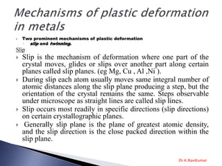
1. Two prominent mechanisms of plastic deformation
◦ slip and twinning.
Slip
Slip is the mechanism of deformation where one part of the
crystal moves, glides or slips over another part along certain
planes called slip planes. (eg Mg, Cu , Al ,Ni ).
During slip each atom usually moves same integral number of
atomic distances along the slip plane producing a step, but the
orientation of the crystal remains the same. Steps observable
under microscope as straight lines are called slip lines.
Slip occurs most readily in specific directions (slip directions)
on certain crystallographic planes.
Generally slip plane is the plane of greatest atomic density,
and the slip direction is the close packed direction within the
slip plane.
Dr.K.RaviKumar
2. The direction of slip planes is indicated in a piece of
metal after deformation by slip bands on the surface of
the metal.
Factors influencing slip
external load and the corresponding value of
shear stress produced by it.
The geometry of crystal structure.
The orientation of active slip planes with the
direction of shearing stresses generated.
5. It results when a portion of crystal takes up an orientation
that is related to the orientation of the rest of the untwined
lattice in a definite, symmetrical way.
The twinned region divides the crystal into two regions in
such a way that the twinned portion of the crystal is a
mirror image of the parent crystal. The plane of symmetry
is called twinning plane.
Each atom in the twinned region moves by a homogeneous
shear a distance proportional to its distance from the twin
plane
FCC - Ag, Au, Cu.
BCC - α-Fe, Ta
HCP - Zn, Cd, Mg, Ti
Twinning may be caused by impact, thermal treatment or by
plastic deformation.
6.
7. Failure can be defined, in general, as an event that does
not accomplish its intended purpose. Failure of a
material component is the loss of ability to function
normally.
Causes for failure
Improper materials selection
Improper processing
Inadequate design
Misuse of a component
Improper maintenance
8. Structural elements and machine elements can fail to perform their
intended functions in three general ways
Excessive elastic deformation (buckling type of failure)- controlled
by the modulus of elasticity, not by the strength of the material.
Excessive plastic deformation or yielding- controlled by the yield
strength of the material.
Fracture
◦ Ductile/brittle fracture
◦ Creep- At elevated temperatures, failure occurs in form of time-
dependent yielding
◦ Fatigue- occurs in parts which are subjected to alternating or
fluctuating stress
11. Exhibits three stages –
(1) after necking, cavities form, usually at inclusions at
second-phase particles, in the necked region because the
geometrical changes induces hydrostatic tensile stresses
(2) the cavities grow, and further growth leads to their
coalesce resulting in formation of crack that grows outward in
direction perpendicular to the application of stress
(3) final failure involves rapid crack propagation at about 45
ْto the tensile axis
12.
13. Takes place with little plastic deformation
It occurs, often at unpredictable levels of stress, by rapid
crack propagation.
The direction of crack propagation is very nearly
perpendicular to the direction of applied tensile stress. This
crack propagation corresponds to successive and repeated
breaking to atomic bonds along specific crystallographic
planes, and hence called cleavage fracture .
14. Takes place in three stages
(1) plastic deformation that causes dislocation pile-
ups at obstacles
(2) micro-crack nucleation as a result of build-up of
shear stresses
(3) eventual crack propagation under applied stress
aided by stored elastic energy
16. Griffith proposed that a brittle material contains number
of micro-cracks which causes stress rise in localized
regions
When one of the cracks spreads into a brittle fracture, it
produces an increase in the surface energy of the sides of
the crack. Source of the increased surface energy is the
elastic strain energy, released as crack spreads.
Griffith’s criteria for propagation of crack include these
terms as: a crack will propagate when the decrease in
elastic energy is at least equal to the energy required to
create the new crack surface.
According to Griffith, such as crack will propagate and
produce brittle fracture when an incremental increase in
its length does not change the net energy of the system.
17. Fatigue occurs when a material is subjected to repeated
loading and unloading.
Failures occurring under conditions of dynamic or alternating
loading are called fatigue failures.
If the loads are above a certain threshold, microscopic cracks
will begin to form at the surface.
Fatigue failure usually occurs at stresses well below those
required for yielding, or in some cases above the yield strength
but below the tensile strength of the material.
These failures are dangerous because they occur without any
warning. Typical machine components subjected to fatigue are
automobile crank-shaft, bridges, aircraft landing gear, etc.
Fatigue failures occur in both metallic and non-metallic
materials
18.
19.
20.
21.
22.
23. Reasons for occurrence of fatigue fracture
(a) a maximum tensile stress of sufficiently
high value.
(b) a large enough variation or fluctuation in
the applied stress.
(c) a sufficiently large number of cycles of
applied stress.
24. I. crack initiation at high stress points (stress
raisers)
◦ crack initiation – includes the early development of fatigue
damage that can be removed by suitable thermal annealing
II. propagation
◦ slip-band crack growth – involves the deepening of initial
crack on planes of high shear stress. This is also known as
stage-I crack growth.
◦ crack growth on planes of high tensile stress – involves
growth of crack in direction normal to maximum tensile
stress, called stage-II crack growth
(d) III. final failure by fracture
◦ final ductile failure – occurs when the crack reaches a size so
that the remaining cross-section cannot support the applied
load.
25. Factors That Affect Fatigue Life
Mean stress (lower fatigue life with increasing smean).
Surface defects (scratches, sharp transitions and edges).
Solution:
polish to remove machining flaws
add residual compressive stress (e.g., by shot peening.)
case harden, by carburizing, nitriding (exposing to appropriate
gas at high temperature)
Environmental Effects
Thermal cycling causes expansion and contraction, hence
thermal stress, if component is restrained.
Solution:
eliminate restraint by design
use materials with low thermal expansion coefficients.
Corrosion fatigue. Chemical reactions induced pits which act as
stress raisers. Corrosion also enhances crack propagation.
Solutions:
decrease corrosiveness of medium, if possible.
add protective surface coating.
add residual compressive stresses.
26. creep is the tendency of a solid material to slowly move or
deform permanently under the influence of stresses.
Creep is more severe in materials that are subjected to heat for
long periods, and near melting point
Creep always increases with temperature.
The rate of this deformation is a function of the material
properties, exposure time, exposure temperature and the
applied structural load.
27.
28. In primary creep, the strain rate is relatively high, but slows
with increasing strain. This is due to work hardening.
The strain rate eventually reaches a minimum and becomes
near constant. This is due to the balance between work
hardening and annealing (thermal softening). This stage is
known as secondary or steady-state creep.
In tertiary creep, the strain rate exponentially increases with
strain because of necking phenomena.
29.
30.
31.
32.
33.
34.
35.
36.
37. There are several standard types of
toughness
Three of the toughness properties that will
be discussed in more detail are
1) impact toughness
2) notch toughness and
3) fracture toughness.
38.
39. Nominal dimensions of gauge (test) section:
◦ 128 mm long and 10 mm2 (Izod)
◦ 55 mm long and 10 mm2 (Charpy)