Land cruiser (engine_[1_vd-ftv]) (2)
•Télécharger en tant que PPT, PDF•
22 j'aime•33,471 vues

engine 1VD FTV landcruiser

Recommandé
Recommandé
Contenu connexe
Tendances
Tendances (20)
En vedette
En vedette (13)
Similaire à Land cruiser (engine_[1_vd-ftv]) (2)
Similaire à Land cruiser (engine_[1_vd-ftv]) (2) (20)
Dernier
Dernier (20)
Land cruiser (engine_[1_vd-ftv]) (2)
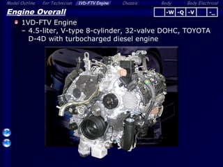
- 1. Body ElectricalModel Outline 1VD-FTV Engine Chassis Bodyfor Technician 1 Engine Overall 1VD-FTV Engine – 4.5-liter, V-type 8-cylinder, 32-valve DOHC, TOYOTA D-4D with turbocharged diesel engine -Q -V -_-W
- 2. Body ElectricalModel Outline 1VD-FTV Engine Chassis Bodyfor Technician 2 Engine Overall Features Cylinder Block Stiffening Plate Hydraulic Lash Adjuster and Roller Rocker Arm VN Type 2 Turbochargers (Driven by DC Motor) Water-cooled Type EGR Cooler Rotary Solenoid Type 2 Diesel Throttles Common-rail System HP4 Supply Pump (3 Plunger) Water-cooled Type Fuel Cooler Wave Stopper Structure for Cylinder Head Gasket -Q -V -_-W
- 3. Body ElectricalModel Outline 1VD-FTV Engine Chassis Bodyfor Technician 3 Engine Overall Features Crankshaft Pulley Installation By 3 Bolts Timing Gear and Chain Liner Solenoid Type 2 EGR Valves Aluminum Cylinder Head Compacted Vermicular Graphite Cast Iron Cylinder Block • Trochoid Type Oil Pump (2 Rotors) • Scavenging Pump • Trochoid Type Oil Pump (2 Rotors) • Scavenging Pump -Q -V -_-W Element Replacement Type Oil Filter
- 4. Body ElectricalModel Outline 1VD-FTV Engine Chassis Bodyfor Technician 4 Engine Overall Features •Element Replacement Type Fuel Filter •Fuel Filter Warning Switch Dash Panel Penetration Installation for ECM -Q -V -_-W • Air-cooled Type Fuel Cooler under the Floor • Fuel Pump in the Fuel Tank (Dual Tank Model Only) • Air-cooled Type Fuel Cooler under the Floor • Fuel Pump in the Fuel Tank (Dual Tank Model Only)
- 5. Body ElectricalModel Outline 1VD-FTV Engine Chassis Bodyfor Technician 5 Engine Overall Specifications Item 1VD-FTV 1VD-FTV 1HD-FTE Model New LAND CRUISER LAND CRUISER (70 Series) Previous Model Destination -W, -Q, -V, Gen -Q -W, -Q, Gen No. of Cylinders and Arrangement 8-Cylinder, V type ← 6-Cylinder, In-line Valve Mechanism 32-valve, DOHC, Chain and Gear Drive ← 24-valve, OHC, Belt and Gear Drive Displacement cm3 (cu. in.) 4461 (272.2) ← 4164 (254.0) Bore x stroke mm (in.) 86.0 x 96.0 (3.39 x 3.78) ← 94.0 x 100.0 (3.70 x 3.94) Compression Ratio 16.8 : 1 ← 18.8 : 1 Emission Regulation -W EUROIV, EUROIII (Except Europe) - EURO III -Q EUROIV ← EURO II -V N.A. - - Gen EUROIII or EUROII or N.A. * N.A. -Q -V -_-W *: It is different depending on the countries
- 6. Body ElectricalModel Outline 1VD-FTV Engine Chassis Bodyfor Technician 6 Engine Overall Specifications Item 1VD-FTV 1VD-FTV 1HD-FTE Model New LAND CRUISER LAND CRUISER (70 Series) Previous Model Destination -W, -Q, -V, Gen -Q -W, -Q, Gen Combustion Chamber Direct Injection Type ← ← Fuel System Common-rail Type ← Distributor Type Turbocharger VN type 2 Turbochargers VN Type Turbocharger Conventional Type Turbocharger Max. Output kW @ rpm -W AT 210 @ 3600 - 150 @ 3400 -W*, -Q AT 195 @ 3400 MT - 151 @ 3400 -V, Gen AT 173 @ 3200 - MT 162 @ 3600 Max. Torque N·m @ rpm -W AT 650 @ 1600 – 2800 - 430 @ 1400 - 3200 -W*, -Q AT 650 @ 1600 – 2600 MT - 430 @ 1200 – 3200 -V, Gen AT 615 @ 1800 – 2200 - MT 430 @ 1200 – 3600 -Q -V -_-W *: Only for -W models equipped with a pre-cleaner
- 7. Body ElectricalModel Outline 1VD-FTV Engine Chassis Bodyfor Technician 7 Reference (Engine Overall) Major Difference From LAND CRUISER (VDJ70) Item 1VD-FTV 1VD-FTV Model New LAND CRUISER (VDJ200) LAND CRUISER 70 Series (VDJ7#) Timing Gear Scissors gear for idle gear N.A. Oil Filter Plastic made filter cap with drain plug Aluminum made filter cap without drain plug Located at engine front side Located at engine rear side Turbocharger 2 turbochargers 1 turbocharger Nozzle-vane is driven by DC motor Nozzle-vane is driven by vacuum actuator Scavenging Pump 1 Rotor 2 Rotors Injector Hole Diameter: 0.113 mm Hole Diameter: 0.105 mm Fuel Tank (Dual Fuel Tank Model Only) Fuel pump in the main tank for fuel transfer Fuel tank select valve Front Engine Mount 2 Electrical Hydraulic Type Conventional Type Cranking Hold Function With N.A. Diagnosis Communication CAN Serial -Q
- 8. Body ElectricalModel Outline 1VD-FTV Engine Chassis Bodyfor Technician 8 Engine Proper Cylinder Block – High strength compacted vermicular graphite cast iron is used for weight reduction Engine Number Stamp Front -Q -V -_-W
- 9. Body ElectricalModel Outline 1VD-FTV Engine Chassis Bodyfor Technician 9 Engine Proper Cylinder Head Gasket – Wave stopper structure is used around the cylinder bore to improve sealing performance Wave Stopper Structure A – A Cross Section A A -Q -V -_-W
- 10. Body ElectricalModel Outline 1VD-FTV Engine Chassis Bodyfor Technician 10 Engine Proper Crankshaft and Flywheel – Balance weight is appropriately provided to reduce vibration Oil Pump Drive Gear MT ModelAT Model -Q -V -_-W Timing Gear Balance Weight (Newly added) Balance Weight (Newly added)
- 11. Body ElectricalModel Outline 1VD-FTV Engine Chassis Bodyfor Technician 11 Engine Proper Cylinder Block Stiffening Plate – This plate connects the bearing cap and cylinder block skirt portion to reduce noise and vibration Cylinder Block Stiffening Plate Plastic Region Tightening Bolts Front Mark -Q -V -_-W
- 12. Body ElectricalModel Outline 1VD-FTV Engine Chassis Bodyfor Technician 12 Engine Proper Crankshaft Pulley – Installed by 3 bolts to reduce tightening torque Installation with 3 bolts (Torque: 115 N·m x3) -Q -V -_-W
- 13. Body ElectricalModel Outline 1VD-FTV Engine Chassis Bodyfor Technician 13 Valve Mechanism Timing Gear and Chain – Timing gear and chain is used to realize maintenance- free Crankshaft Timing Gear Timing Chains Idle Gear Supply Pump Drive Gear (Sprocket) Oil Jet Chain Tensioner Chain Tensioner Power Steering Vane Pump Drive Gear Camshaft Timing Sprocket (LH) Oil Jet -Q -V -_-W Camshaft Timing Sprocket (RH)
- 14. Body ElectricalModel Outline 1VD-FTV Engine Chassis Bodyfor Technician 14 Valve Mechanism Timing Gear and Chain – Scissors gear is used for exhaust camshaft timing gear and idle gear to reduce gear noise Idle Gear Scissors Gear Exhaust Camshaft Timing Gear -Q -V -_-W Scissors Gear
- 15. Body ElectricalModel Outline 1VD-FTV Engine Chassis Bodyfor Technician 15 Lubrication System Oil Pump – Compact and high efficiency trochoid gear (2-rotor) type oil pump is used A Driven Gear Trochoid Gear (2-rotor) View from A Inlet Outlet -Q -V -_-W Oil Pump Driven Gear Oil Pump Drive Gear (Crankshaft) Scavenging Pump Driven Gear
- 16. Body ElectricalModel Outline 1VD-FTV Engine Chassis Bodyfor Technician 16 Lubrication System Oil Filter – Element replacement type oil filter is used Oil Filter Cap (Resin) Oil Filter Element Oil Pan No.1 -Q -V -_-W Drain Bolt
- 17. Body ElectricalModel Outline 1VD-FTV Engine Chassis Bodyfor Technician 17 Lubrication System Scavenging Pump – This system is used to prevents oil from retaining in the turbocharger when driving on slope way Engine condition when driving on slope way Scavenging Pump Oil Outlet Pipe [With This System] [Without This System] No Oil Retention No Oil Retention Oil Retention Oil Retention Return -Q -V -_-W
- 18. Body ElectricalModel Outline 1VD-FTV Engine Chassis Bodyfor Technician 18 Lubrication System Scavenging Pump – Scavenging pump sucks the engine oil in the catch tank and discharge it to the oil pan Oil Catch Tank Air Rotor Scavenging Pump Oil Pan Ventilation Tube To Cylinder Head Cover -Q -V -_-W Turbocharger (RH)Turbocharger (LH) Oil Catch Tank Air Ventilation Tube To Cylinder Head Cover
- 19. Body ElectricalModel Outline 1VD-FTV Engine Chassis Bodyfor Technician 19 Lubrication System Scavenging Pump – Parts Location Turbocharger (LH (Bank2)) Scavenging Pump Oil Catch Tank Ventilation Tube Front -Q -V -_-W Turbocharger (RH (Bank1)) Oil Catch Tank Ventilation Tube
- 20. Body ElectricalModel Outline 1VD-FTV Engine Chassis Bodyfor Technician 20 Lubrication System Scavenging Pump – Scavenging pump is driven by crankshaft Driven Gear A View from A Outlet Oil Pump Driven Gear Oil Pump Drive Gear (Crankshaft) Scavenging Pump Driven Gear Rotor -Q -V -_-W Inlet
- 21. Body ElectricalModel Outline 1VD-FTV Engine Chassis Bodyfor Technician 21 Lubrication System Scavenging Pump – Oil catch tank separates the engine oil to air-liquid Oil Catch Tank Ventilation Tube Turbocharger -Q -V -_-W RH Side (Bank1)LH Side (Bank2) Air: Oil:
- 22. Body ElectricalModel Outline 1VD-FTV Engine Chassis Bodyfor Technician 22 Reference (Lubrication System) Scavenging Pump – Oil flow from oil catch tank to scavenging pump To Scavenging Pump To Scavenging Pump From Oil Catch Tank (RH) From Oil Catch Tank (LH) Front Oil Pan No.1 -Q -V -_-W
- 23. Body ElectricalModel Outline 1VD-FTV Engine Chassis Bodyfor Technician 23 Intake and Exhaust System Variable Nozzle Vane Type Turbocharger – VN (Variable Nozzle-vane) type 2 turbochargers VN Type 2 Turbochargers Intercooler -Q -V -_-W Air Cleaner
- 24. Body ElectricalModel Outline 1VD-FTV Engine Chassis Bodyfor Technician 24 Intake and Exhaust System Variable Nozzle Vane Type Turbocharger – Nozzle Vane is driven by DC motor RH Side (Bank1) LH Side (Bank2) : Intake Air : Exhaust Gas DC Motor Nozzle Vane Position Sensor -Q -V -_-W
- 25. Body ElectricalModel Outline 1VD-FTV Engine Chassis Bodyfor Technician 25 Intake and Exhaust System Variable Nozzle Vane Type Turbocharger – Construction (RH Side (Bank1)) DC Motor Linkage Nozzle Vane Turbine Wheel Nozzle Vane Position Sensor Intake Air Exhaust Gas RH Side (Bank1) -Q -V -_-W
- 26. Body ElectricalModel Outline 1VD-FTV Engine Chassis Bodyfor Technician 26 Intake and Exhaust System Variable Nozzle Vane Type Turbocharger – Nozzle angle changes to increase exhaust gas speed – VN turbo can be effected at lower engine speed At low engine speed (Exhaust gas pressure is low) At high engine speed (Exhaust gas pressure is high) Narrower Wider Gas speed up Turbine wheel speed up -Q -V -_-W
- 27. Body ElectricalModel Outline 1VD-FTV Engine Chassis Bodyfor Technician 27 ECM Intake and Exhaust System Variable Nozzle Vane Type Turbocharger – Control Nozzle Vane Position Turbo Motor Driver [for Bank1 (RH)] Target Position Control Status Manifold Absolute Pressure Sensor Atmospheric Temp. Sensor Atmospheric Pressure Sensor Engine Coolant Temp. Sensor Injector (EDU) Crankshaft Position Sensor DC Motor Nozzle Vane Position Sensor Control Turbo Motor Driver [for Bank2 (LH)] VNTO VNTI VNO2 VNI2 -Q -V -_-W
- 28. Body ElectricalModel Outline 1VD-FTV Engine Chassis Bodyfor Technician 28 ECM Turbo Motor Driver [for Bank1 (RH)] EFI Relay +B GND DC Motor M+ M-VNTI VNTO VN Close VN Open Reference (Intake and Exhaust System) Variable Nozzle Vane Type Turbocharger – System diagram of turbo motor driver Nozzle Vane Position Sensor VNTI VNTO VTA1 VTA2 Battery Target Position Status Signal -Q -V -_-W
- 29. Body ElectricalModel Outline 1VD-FTV Engine Chassis Bodyfor Technician 29 Reference (Intake and Exhaust System) Variable Nozzle Vane Type Turbocharger – Location of turbo motor driver Turbo Motor Driver (For Bank1) Turbo Motor Driver (For Bank2) -Q -V -_-W
- 30. Body ElectricalModel Outline 1VD-FTV Engine Chassis Bodyfor Technician 30 Intake and Exhaust System Diesel Throttle – Rotary solenoid type 2 diesel throttles are used -Q -V -_-W 2 Diesel Throttles Intercooler
- 31. Body ElectricalModel Outline 1VD-FTV Engine Chassis Bodyfor Technician 31 Intake and Exhaust System EGR System – Liner solenoid type 2 EGR valves – Water-cooled type EGR cooler EGR Cooler 2 EGR Valves Exhaust Manifold → EGR Cooler -Q -_-W
- 32. Body ElectricalModel Outline 1VD-FTV Engine Chassis Bodyfor Technician 32 Fuel System Components and Features 3 Plunger Type HP4 Supply Pump • Element Replacement Type Fuel Filter • Fuel Filter Warning Switch • Recirculation Type Fuel Heater Air-cooled Fuel Cooler Fuel Pressure Sensor Pressure Limiter 2 Common-rails for each bank RH 9-hole Type Solenoid Injector LH -Q -V -_-W Jet Pump Fuel Tank (Main) Fuel Tank (Sub) Fuel Pump Dual Tank Model Only Water-cooled Fuel Cooler With Fuel Heater Model Only Dual Tank Model Only 2 Return Paths
- 33. Body ElectricalModel Outline 1VD-FTV Engine Chassis Bodyfor Technician 33 Fuel System Common-rail – 2 Common-rails for each bank -Q -V -_-W Common-railsPressure Sensor Pressure Limiter Supply Pump Front Injector
- 34. Body ElectricalModel Outline 1VD-FTV Engine Chassis Bodyfor Technician 34 Fuel System Supply Pump (HP4) – 3 plunger type supply pump is used to correspond to the injection volume increase Return Inlet 3 Plungers Outlet -Q -V -_-W
- 35. Body ElectricalModel Outline 1VD-FTV Engine Chassis Bodyfor Technician 35 Fuel System Injector – 9-hole type solenoid injector is used From Common-rail Return to Fuel Tank ∅0.113 mm Injector Compensation Code (30-digit) -Q -V -_-W
- 36. Body ElectricalModel Outline 1VD-FTV Engine Chassis Bodyfor Technician 36 Fuel System EDU – 2 EDUs are used -Q -V -_-W EDU for #1,4,6,7 EDU for #2,3,5,8
- 37. Body ElectricalModel Outline 1VD-FTV Engine Chassis Bodyfor Technician 37 Fuel System Fuel Filter – Element replacement type fuel filter is used Fuel Filter From Fuel Tank To Supply Pump -Q -V -_-W
- 38. Body ElectricalModel Outline 1VD-FTV Engine Chassis Bodyfor Technician 38 Fuel System Fuel Filter – Main Components Filter Element Fuel Sedimenter Level Warning Switch Bolt x3 Fuel Filter Warning Switch Priming PumpFilter Cap Bracket Filter Case -Q -V -_-W Recirculation Type Fuel Heater (Only for –W and Gen) Drain Cock
- 39. Body ElectricalModel Outline 1VD-FTV Engine Chassis Bodyfor Technician 39 Fuel System Fuel Filter – When the fuel filter clogging is detected by fuel filter warning switch, fuel filter replacement is required Fuel Filter Warning Switch Cloggin g Fuel Filter Multi-information Display (Optitron Type Combination Meter) -Q -V -_-W Analog Type Combination Meter Fuel System Warning Light
- 40. Body ElectricalModel Outline 1VD-FTV Engine Chassis Bodyfor Technician 40 Fuel System Fuel Filter – Fuel filter warning switch is turned OFF when the filter outlet pressure decreases Fuel Filter Warning Switch To Supply Pump Filter Element Normal Fuel Filter (Switch: ON) Fuel Filter Clogged Up (Switch: OFF) Diaphragm ON Meter ECU Fuel Filter Warning Switch To Supply Pump OFF Meter ECU Negative Pressure -Q -V -_-W
- 41. Body ElectricalModel Outline 1VD-FTV Engine Chassis Bodyfor Technician 41 Analog Type Combination Meter Fuel System Fuel Filter (Analog Type Combination Meter Only) – Warning light condition for fuel filter / fuel sedimenter Warning Warning Method Priority Sedimenter Warning Blink 1 Fuel Filter Warning ON 2 -Q -V -_-W
- 42. Body ElectricalModel Outline 1VD-FTV Engine Chassis Bodyfor Technician 42 Fuel System Fuel Filter – After the fuel filter replacement, perform the reset operation to turn off the warning message/light -Q -V -_-W Reset operation is same as 1KD/2KD engine on HIACE and IMV Reset OperationReset Operation Within 3 - 60 sec. Connect 3 sec. Fuel Filter Replacement (fuel filter warning switch connector disconnected) ON (IG) Warning message is turned OFF
- 43. Body ElectricalModel Outline 1VD-FTV Engine Chassis Bodyfor Technician 43 Fuel System Fuel Cooler – Water-cooled type fuel cooler at the V bank From Cylinder Block From Left Bank Injector From Right Bank Injector Return Fuel : Coolant Flow : Fuel FlowTo Water Pump View from A ↑ Front A -Q -V -_-W
- 44. Body ElectricalModel Outline 1VD-FTV Engine Chassis Bodyfor Technician 44 Fuel System Fuel Cooler – Air-cooled type fuel cooler under the floor To Fuel Tank From Engine Front -Q -V -_-W Fuel Cooler
- 45. Body ElectricalModel Outline 1VD-FTV Engine Chassis Bodyfor Technician 45 Fuel Tank (Main) [93-liter] Fuel Tank (Sub) [45-liter] Fuel System Fuel Pump (Dual Fuel Tank Model Only) – Fuel pump is provided in the main tank to transfer the fuel in sub tank to main tank Fuel Pump Jet Pump -Q -V -_ Fuel Transfer System ECMEngine
- 46. Body ElectricalModel Outline 1VD-FTV Engine Chassis Bodyfor Technician 46 Fuel System Fuel Pump (Dual Fuel Tank Model Only) – Location -Q -V -_ Fuel Tank (Main) [93-liter] Fuel Tank (Sub) [45-liter] Fuel Line [Sub Tank to Jet Pump (Main Tank)] Jet Pump Fuel Pump Front
- 47. Body ElectricalModel Outline 1VD-FTV Engine Chassis Bodyfor Technician 47 Fuel System Fuel Pump (Dual Fuel Tank Model Only) – ECM controls a fuel pump in accordance with the amount of fuel consumption -Q -V -_ ECM Injection Volume Fuel Consumption Main Sub ECM operates the fuel pump for fuel transfer Fuel Pump Relay Fuel Pump Control
- 48. Body ElectricalModel Outline 1VD-FTV Engine Chassis Bodyfor Technician 48 Fuel System Fuel Pump (Dual Fuel Tank Model Only) – When the malfunction is detected in the fuel transfer system, the fuel level warning light is blinked -Q -V -_ Fuel transfer operation is not normal Main Sub 20.7-liter 7.8-liter or more Blink
- 49. Body ElectricalModel Outline 1VD-FTV Engine Chassis Bodyfor Technician 49 Engine Mount Electrical Hydraulic Type Engine Mount – The electrical hydraulic type is used for the front engine mounts to reduce the engine vibration at idling Front Engine Mounts -Q -V -_-W No.1 Fluid Chamber No.2 Fluid Chamber Diaphragm Rubber To VSV VSV Vacuum Pump Vacuum Line
- 50. Body ElectricalModel Outline 1VD-FTV Engine Chassis Bodyfor Technician 50 Engine Mount Electrical Hydraulic Type Engine Mount – System Diagram Electrical Hydraulic type Engine Mounts -Q -V -_-W Vehicle Speed Engine Speed ECMVSV Vacuum Pump
- 51. Body ElectricalModel Outline 1VD-FTV Engine Chassis Bodyfor Technician 51 Engine Mount Electrical Hydraulic Type Engine Mount – Mount characteristic -Q -V -_-W VSV ON = SoftVSV OFF = Hard No.1 Fluid Passage No.2 Fluid Passage VacuumNo vacuum
- 52. Body ElectricalModel Outline 1VD-FTV Engine Chassis Bodyfor Technician 52 VSV OFF (Hard) Engine Mount Electrical Hydraulic Type Engine Mount – When the engine is idling and vehicle is driving at a low speed, the VSV is turned ON VSV ON (Soft) Engine Speed Vehicle Speed VSV OFF *1 *1: During engine cranking (vacuum is unstable) -Q -V -_-W Operating Condition
- 53. Body ElectricalModel Outline 1VD-FTV Engine Chassis Bodyfor Technician 53 Engine Control System ECM – Dash panel penetration installation ECM -Q -V -_-W Gasket (Non-reusable Part) ECM Body
Notes de l'éditeur
- [1VD-FTV Engine] 4.5-liter, V-type 8-cylinder, 32-valve DOHC, TOYOTA D-4D with turbocharged diesel engine
- [Features of 1VD-FTV] - Cylinder Block Stiffening Plate - Wave Stopper Structure for Cylinder Head Gasket - Hydraulic Lash Adjuster and Roller Rocker Arm - Rotary Solenoid Type 2 Diesel Throttles - Water-cooled Type EGR Cooler - VN (Variable Nozzle-vane) Type 2 Turbochargers (Driven by DC Motor) - Common-rail System - HP4 Supply Pump (3 Plunger) Water-cooled Type Fuel Cooler HP = High Pressure
- [Features of 1VD-FTV] - Compacted Vermicular Graphite Cast Iron Cylinder Block - Aluminum Cylinder Head - Crankshaft Pulley Installation By 3 Bolts - Timing Gear and Chain - Trochoid Type Oil Pump (2 Rotors) - Scavenging Pump - Element Replacement Type Oil Filter - Liner Solenoid Type 2 EGR Valves
- [Features of 1VD-FTV] - Element Replacement Type Fuel Filter - Fuel Filter Warning Switch - Air-cooled Type Fuel Cooler under the Floor - Dash Panel Penetration Installation for ECM - [Dual Tank Model Only] Fuel Pump in the Fuel Tank for Fuel Transfer
- [Coolant Capacity] AT Model: 14.8 Liters (15.6 US qts, 13.0 Imp. qts) MT Model: 15.4 Liters (16.3 US qts, 13.6 Imp. qts) With Rear Heater Model (-W, -Q, Gen. Only): + 2.80 Liters (2.95 US qts, 2.46 Imp. qts) With Viscous Heater Model (-W only): + 0.40 Liters (0.42 US qts, 0.35 Imp. qts) [Oil Capacity] Dry: 9.7 Liters (10.3 US qts, 8.5 Imp. qts) With Oil Filter: 9.0 Liters (9.5 US qts, 7.9 Imp. qts) Without Oil Filter: 8.0 Liters (8.5 US qts, 7.0 Imp. qts)
- Balance weight is appropriately provided for the crankshaft and flywheel to reduce vibration.
- [Tightening Torque] - Plastic Region Tightening Bolts (Inside): 35 N·m + 180° - Plastic Region Tightening Bolts (Outside): 60 N·m + 90°
- Three bolts tighten the crankshaft pulley onto the crankshaft to reduce the tightening torque and improve serviceability. Tightening Torque: 115 N·m x3 Reference: Tightening Torque for 1HD-FTE: 430 N·m
- Timing gear and 2 timing chains are used.
- 2-rotor type oil pump is used.
- Oil filter cap made by resin.
- When driving on slope way, the engine oil retains in the turbocharger if this system isn't equipped. On the models with this system, the conventional oil outlet pipe for turbocharger is discontinued and scavenging pump is added to prevents oil from retaining in the turbocharger. The scavenging pump suctions the return oil of turbocharger and sends it to the oil pan. It securing the reliability of the engine.
- Scavenging Pump: Sucks the engine oil in catch tank and discharge it to the oil pan. Oil Catch Tank: Separate the engine oil to air-liquid.
- Scavenging pump is the trochoid gear type oil pump. The scavenging pump (bearing portion etc.) is lubricated by rotating the scavenging pump.
- 2 turbochargers are used for each bank.
- Variable nozzle vane type turbocharger to ensure higher effectiveness in full range. Nozzle vane is driven by the DC motor. Water-cooled type turbocharger
- Depending on the engine speed, angle of vane is changed. [At low engine speed] Vane angle is changed to make narrower exhaust gas passage. Thus, the exhaust gas speed applied to turbine is increased to spin the turbine with higher speed. [At high engine speed] Vane angle is changed to make wider exhaust gas passage.
- This system is controlled by the ECM. 2 turbo motor drivers are used for each turbocharger.
- For all model
- EGR system is used for EUROIV, EUROIII or EURO II model. The EGR passage is provided in the cylinder head. Laminated structure type EGR cooler is used.
- [Features of Fuel System] - Common-rail system is used - 3 plunger type HP4 supply pump - 9-hole type solenoid injector - 2 Common-rails for each bank - Water-cooled type fuel cooler - Air-cooled type fuel cooler at the under floor - Element replacement type fuel filter - Fuel filter warning switch is used to detect filter clogging - Recirculation type fuel heater (-W: STD / Gen: OPT) - [Dual Tank Model Only (-Q, -V, Gen)] Fuel pump is provided in the main fuel tank to transfer the fuel in sub tank to main tank There are 2 return paths to prevent the pressure of the return fuel from increasing. If the pressure of the return fuel increases, the performance of fuel system parts decreases. On the dual fuel tank model, the return tube passes through the sub fuel tank and returns to the main fuel tank. This construction utilizes the heat of the return fuel that has been warmed by the engine to prevent the temperature in the sub fuel tank from decreasing. If the temperature in the sub fuel tank decreases, the fuel viscosity become high and the fuel transfer does not operate normally.
- [Common-rail Pressure] EURO IV Model: 25 ~ 175 MPa Except EURO IV Model: 25 ~ 129 MPa
- 3 plunger type supply pump is used to correspond to the injection volume increase by high displacement and high output engine.
- 9-hole type solenoid injector Small injection hole ( 0.113 mm)
- Element replacement type fuel filter is used.
- The filter cap is installed by the bolt to improve serviceability at the element replacement. Recirculation type fuel heater is used for –W as standard equipment and -_ as optional equipment.
- [Optitron Type Combination Meter] When the fuel filter clogging is detected by fuel filter warning switch, “Fuel Filter Maintenance Reqd” message is displayed on the multi-information display in combination meter. It shows that the fuel filter replacement is required. Note: Master warning light is turned on with the indication of the warning message. [Analog Type Combination Meter] When the fuel filter clogging is detected by fuel filter warning switch, the Fuel System Warning Light is turned on. It shows that the fuel filter replacement is required.
- Fuel filter warning switch is same as KD series engine on HIACE and IMV. Fuel filter clogging system: Vacuum switch Filter element is clogged, suction from supply pump generates higher negative pressure in fuel pipe. Then, switch is turned off.
- Analog Type Combination Meter Only This warning light is for both filter warning and sedimenter warning. Warning condition: - Sedimenter warning: blink - Fuel filter warning: stays on If the both sedimenter and fuel filter warning are detected, the warning light blinks (as sedimenter warning).
- The clogging detection is memorized in EEPROM and the warning message/light is indicated until reset operation is performed. After the fuel filter replacement, perform the reset operation to turn off the warning message/light. Reset operation is same as KD series engine on HIACE and IMV. [Reset Operation] 1. After the fuel filter replacement, turn the engine switch on (IG). (The fuel filter warning switch connector should be disconnected before engine switch on (IG).) 2. Connect the fuel filter warning switch connector within 3 – 60 sec. after engine switch on (IG). 3. 3 sec. after the step2, warning message/light is turned OFF.
- Water-cooled type fuel cooler cools the return fuel from injector.
- Air-cooled type fuel cooler cools the return fuel from engine (injector).
- Fuel pump and jet pump are used to transfer the fuel in the sub tank to main tank. Note: The fuel tank change over system which is used with previous model is discontinued. [Sub Fuel Tank] - Standard equipment for –Q and –V - Optional equipment for -_ - Not equipped for -W
- ECM controls a fuel pump in accordance with the amount of fuel consumption. The fuel pump in the fuel tank operates the jet pump for fuel transfer.
- When the Meter ECU detects the malfunction in the fuel transfer system, the fuel level warning light is blinked. [Malfunction Detection Condition] Fuel of 7.8-liter or more remains in the sub tank when the fuel level of the main tank becomes 20.7-liter. Above condition shows that the fuel transfer operation is not done normally.
- The electrical hydraulic type is used for the front engine mounts to reduce the engine vibration at idling.
- [When the VSV is OFF] Vacuum is not introduced to the engine mount. The fluid passes the No.1 fluid passage only. Mount Characteristic = Hard [When the VSV is ON] Vacuum is introduced to the engine mount and the No.2 fluid passage is opened. The fluid passes the No.1 and No.2 fluid passage. Mount Characteristic = Soft
- When the engine is idling and vehicle is driving at a low speed, the VSV is turned ON (mount = soft) to reduce engine vibration.
- Dash panel penetration installation is adopted a countermeasure for heat. ECM with waterproof connector. Note: This vehicle uses a fluid coupler driven cooling fan. This system does not control heat in the engine compartment as well as electric cooling fans therefore the ECM is in the cab area for temperature control and the connector is in the engine compartment so that the wire harness does not have to route through the dash panel.