SlideShare une entreprise Scribd logo
1  sur  26
Lecture Notes on Green Buildings
Energy and Resource Conservation Page 1
ENERGY AND RESOURCE CONSERVATION
BUILDING ENVELOPE
The concept of a building envelope relates to design and construction of the exterior of the
house. The building envelope of a house consists of its roof, sub floor, exterior doors,
windows and exterior walls. A good building envelope involves using exterior wall materials
and designs that are climate-appropriate, structurally sound and aesthetically pleasing. These
three elements are the key factors in constructing your building envelope.
The building envelope is the outer shell that maintain a dry, heated, or cooled indoor
environment and facilitate its climate control. Building envelope design is a specialized area
of architectural and engineering practice that draws from all areas of building science and
indoor climate control.
The many functions of the building envelope can be separated into three categories:
 Support (to resist and transfer structural and dynamic loads)
 Control (the flow of matter and energy of all types)
 Finish (to meet desired aesthetics on the inside and outside)
The building envelope must be properly designed, constructed, and maintained to prevent
water and air infiltration through the envelope, and prevent moisture condensation within the
envelope system(s).
PURPOSE OF BUILDING ENVELOPE
 Water Resistance: Seepage of rainwater and moisture are the most important aspects.
One of the main purposes of a roof is to resist water. Walls do not get as severe water
exposure as roofs but still leak water. Types of wall systems with regard to water
penetration are barrier, drainage and surface-sealed walls. Generally most materials will
not remain sealed over the long term but ordinary residential construction often treats
walls as sealed-surface systems.
 Air flow control: Control of air flow is important to ensure indoor air quality, control
energy consumption, avoid condensation, and to provide comfort. Control of air
movement includes flow through the enclosure or through components of the building
envelope itself, as well as into and out of the interior space.
 Thermal envelope: It is a part of a building envelope but may be in a different location
such as in a ceiling. Its efficiency is based on providing insulation and reduction in
temperature from outside to inside.
Lecture Notes on Green Buildings
Energy and Resource Conservation Page 2
Types of Building envelopes
 Dual stage and
 Single stage
 Dual Stage: A dual-stage system includes a primary barrier with a secondary
waterproofing system. An example of a dual-stage system is a brick masonry veneer wall.
The brick veneer is the primary barrier, but because water readily migrates through
masonry, a secondary waterproofing membrane and flashing system are provided to
capture and divert water back to the exterior. If weep holes (openings in the masonry to
allow water to drain) are covered with sealant, water can back up in the cavity behind the
brick, potentially causing more problems.
Fig: Brick masonry veneer wall
 Single-stage system: It relies on the exterior “skin” to prevent leakage without a
secondary system to manage water leakage. Examples of single-stage systems are roof
membranes and insulated metal panels. In single-stage systems, any water leakage (or
condensation) behind the exterior skin typically becomes trapped and prematurely
deteriorates the system. Regardless of the type of system, flashing must be reliably
integrated to prevent or capture and manage leakage.
Lecture Notes on Green Buildings
Energy and Resource Conservation Page 3
Fig: Single stage system
For new buildings, unreliable building envelopes can allow water leakage from the
beginning, requiring significant effort to correct deficient components. For existing buildings,
as maintenance is deferred, water infiltration into the wall system can go unnoticed for long
periods of time, with building components continuing to deteriorate. With construction costs
increasing annually and the amount and extent of deterioration multiplying, the cost of a
comprehensive building envelope restoration project significantly increases. Provision of
Insulation materials is essential in the wall of building to reduce heat transfer from outside to
inside.
Fig: Wall insulation Fig: Wall insulation
PASSIVE ENERGY SYSTEMS
Passive energy systems operate without the reliance on external devices. Rather, such as in
greenhouses, solariums and sunrooms, solar energy captures sunbeams through glass
windows that absorb and retain heat. Passive solar systems include these features:
 Passive collectors usually rely on south-facing windows to convert rays into sunlight.
 Design of passive solar collectors is based on the law of thermodynamics, which posits
that heat transfers from warm to cool surfaces, such as through convection.
 The success of the passive solar system depends on its orientation and the thermal mass
of its walls, which determine its ability to absorb heat.
Lecture Notes on Green Buildings
Energy and Resource Conservation Page 4
Examples:
Building a well designed, passive solar house can mean comfort in both summer and winter,
with minimal energy inputs. On the hottest day of summer, it’s comfortable and cool inside.
On the coldest night of the year, passively collected solar heat warms your bones.
In temperate climates, the summer days are hot but most nights are cool. And the winter
nights are cold, while the winter days often bring some sun. All these factors can be utilized
to create a comfortable home all year round. Primary to temperate passive house design is
three big factors: good insulation, good thermal mass, and good solar gain.
Fig: Passive solar energy house Fig: Elements of Passive solar energy
 Good insulation: placed on the outer layer of the house walls and also in the roof cavity,
to stop heat entering or leaving the house. This might be in the form of straw bale walls,
light earth, or some other insulative materials.
 Good thermal mass: this goes on the inside of the house, to store heat – thick earth
render on the inside of walls, internal mud brick walls, earth, mud brick or stone floors,
and so on.
 Solar gain: the side of the house that faces the equator (north, here in Australia) is the
warm side in winter and should have the majority of the windows. This will allow lots of
solar energy to enter the building in the winter, and this basic premise can be used to
lower winter energy costs.
Lecture Notes on Green Buildings
Energy and Resource Conservation Page 5
In winter, the nights are properly cold, with slightly warmer days that are sometimes sunny.
This is the season of creating the blanket effect. In short, the aim in winter is to collect and
store heat energy in the house, and let it out as little as possible.
 Catching heat: The most passive way to catch heat energy is to utilize the sun, with good
house design. Big equatorial facing windows allow the low winter sun to shine into the
house and onto the floor and interior walls. Well-designed eave angles support this by
letting the lower sun into the equatorial side of the house in winter, but not in summer
when the sun is high.
A glasshouse on the equatorial side of a building, which opens into the main space, will
further enhance this effect. Solar energy is caught and the warmed air escapes into the
main house, warming it considerably. Wood stoves are another effective aspect for winter
heating, especially if they’re also cooking your food and heating your water, as well as
warming the house. If fuelled by sustainably harvested firewood, they’re another form
of regenerative + effective energy.
 Storing heat: This is where the internal thermal mass of the house comes in – day after
day, the thermal mass of the internal walls and floor slowly but surely absorb all that heat.
Over time, this builds up to be a considerable heat bank that ‘gives back’ on a 24 hour
basis, little by little. Completely passive heating. The insulation’s job is to prevent that
heat escaping – the outside walls and the roof space must surround and store this internal
pocket of heat, like a blanket.
Active Energy Systems
Active solar heating systems use solar energy to heat a fluid -- either liquid or air -- and then
transfer the solar heat directly to the interior space or to a storage system for later use. If the
solar system cannot provide adequate space heating, an auxiliary or back-up system provides
the additional heat. Liquid systems are more often used when storage is included, and are
well suited for radiant heating systems, boilers with hot water radiators, and even absorption
heat pumps and coolers. Both liquid and air systems can supplement forced air systems.
Examples:
Active solar power setups rely on external energy sources or backup systems, such as
radiators and heat pumps to capture, store and then convert solar energy into electricity.
Depending on the complexity of the design, it can heat or cool the home or provide power to
an entire neighbourhood. Active solar systems include the following features:
Lecture Notes on Green Buildings
Energy and Resource Conservation Page 6
 The collectors are made up of flat-plate PV panels, which are usually mounted and
stationary and transfer heat from the solar collector. In advanced designs, panels are
often connected with each other to form modules.
 Heating water or an antifreeze solution, liquid-based systems circulate the heated liquid
through a heat exchanger connected to a storage tank. Air-based systems heat air in a
solar air collector and then fans distribute the heated air, circulating it around the home
or property as needed for space heating. Energy storage technologies may also be
employed with solar heating systems to provide heat when there’s no sunshine, and at
night. Energy storage may also be used with solar cooling and solar water heating
applications.
Fig: Active solar energy system Fig: Solar air heat in buildings
Operation
 Solar Heating: In the solar PV collector, a heat transfer or "working" fluid such as water,
antifreeze (usually non-toxic propylene glycol), or other type of liquid absorbs the solar
heat. At the appropriate time, a controller operates a circulating pump to move the fluid
through the collector. The liquid flows rapidly, so its temperature only increases 10° to
20°F (5.6° to 11°C ) as it moves through the collector. The liquid flows to either a storage
tank or a heat exchanger for immediate use. Heating a smaller volume of liquid to a
higher temperature increases heat loss from the collector and decreases the efficiency of
the system. Other system components include piping, pumps, valves, an expansion tank, a
heat exchanger, a storage tank, and controls.
 Storage of Heat: Liquid systems store solar heat in tanks of water that are made up of
stainless steel, fiber glass, concrete etc. based on the limits of operating temperature and
pressure. In tank type storage systems, heat from the working fluid transfers to a
distribution fluid in a heat exchanger exterior to or within the tank. Tanks are pressurized
or unpressurized, depending on overall system design. The simplest storage system option
is to use standard domestic water heaters. They meet building codes for pressure vessel
requirements, are lined to inhibit corrosion, and are easy to install.
 Distribution of heat in the room: A radiant floor or a central forced-air system is used to
distribute the solar heat. In a radiant floor system, solar-heated liquid circulates through
Lecture Notes on Green Buildings
Energy and Resource Conservation Page 7
pipes embedded in a thin concrete slab floor, which then radiates heat to the room.
Radiant floor heating is ideal for liquid solar systems because it performs well at
relatively low temperatures. A carefully designed system may not need a separate heat
storage tank, although most systems include them for temperature control. A conventional
boiler or even a standard domestic water heater can supply back-up heat. The slab is
typically finished with tile. Radiant slab systems take longer to heat the home from a
"cold start" than other types of heat distribution systems. Once they start operating, they
provide a consistent level of heat.
In the forced-air system, a liquid-to-air heat exchanger, or heating coil, is placed in
the main room-air return duct before it reaches the furnace. Air returning from the living
space is heated as it passes over the solar heated liquid in the heat exchanger. Additional
heat is supplied as necessary by the furnace. The coil must be large enough to transfer
sufficient heat to the air at the lowest operating temperature of the collector.
The two systems that are commonly adopted have their own advantages and disadvantages
and are summarized below:
Passive energy systems
S No Advantages Disadvantages
1 Suitable for a small installation Its efficiency depends on the weather
2 It requires no external equipment, so it’s
usually cheaper
It has the potential to overheat the
buildings, if it is located in a warm
climate.
3 It’s better than an active system since it does
not rely on radiators or furnaces that dry out
the mucous membranes or cause allergies
It requires a careful and proper
choice in windows for maximum
efficiency
4 Reduction in the energy costs
Active energy systems
S No Advantages Disadvantages
1 No dependence of external weather as
heating is through equipment installed
The fluids that most efficiently store
heat have the potential to release
toxic chemicals into the air
2 No release of air emissions in atmosphere High maintenance cost
3 Operation of PV panels for heating Requires expensive external
equipment
4 No noise pollution .
TYPES OF ENERGY USED IN COMMERCIAL BUILDINGS
Systems used:
 Electricity, diesel and natural gas
Lecture Notes on Green Buildings
Energy and Resource Conservation Page 8
 Solar and wind energy systems
 Biomass and geothermal energy systems
Purposes:
 Central heating and cooling systems
 Electricity and electrical appliances
 Hot water and water pumping
ENERGY USED IN TRANSPORTATION AND CONSTRUCTION PROCESSES
The energy used in building materials and buildings is divided into four categories:
 Embodied energy including Energy consumption during building construction: It is
non-renewable energy required to initially produce a building and maintain it during its
useful life. It includes energy used to acquire, process and manufacture the building
materials, including any transportation related to these activities (indirect energy); energy
used to transport building products to the site and construct the building (direct energy);
and energy consumed to maintain, repair, restore, refurbish or replace materials,
components or systems during the life of the building (recurring energy).
 Operational Energy: It is the energy is required for heating, cooling, ventilation,
lighting, equipment and appliances.
 Decommissioning Energy: It is the energy used for demolition/deconstruction of the
building and transporting demolished/salvaged materials to landfill/recycling centres.
Embodied energy is measured as a quantity of non-renewable energy per unit of building
material, component or system. It may be expressed as mega Joules (MJ) or Giga Joules (GJ)
per unit of weight (Kg) or area (square meter). Associated environmental impact is implicit in
the measure of embodied energy. As a rule of thumb, embodied energy is a reasonable
indicator of the overall environmental impact of building material, assemblies or system.
Although most of the focus for improving energy efficiency in buildings has been on their
operational emissions, it is estimated that about 30% of all energy consumed throughout the
lifetime of a building can be in its embodied energy (this percentage varies based on factors
such as age of building, climate, and materials). In the past, this percentage was much lower,
but as much focus has been placed on reducing operational emissions (such as efficiency
improvements in heating and cooling systems), the embodied energy contribution has come
much more into play.
Energy consumed due to transportation of building materials from initial stage to finished
stage and to the site is a part of embodied energy. It is estimated as equivalent to 1.5% of the
total embodied energy based on a survey conducted. This figure will naturally increase when
return journeys, vehicle manufacture and maintenance and the road network infrastructure are
considered. This depends on the state, shape, densities and percentage of truck volume that is
filled with the materials that are transported to the site.
Lecture Notes on Green Buildings
Energy and Resource Conservation Page 9
BUILDING AUTOMATION AND BUILDING MANAGEMENT SYSTEM
 Building automation: It is the automatic centralized control of a building's heating,
ventilation and air conditioning, lighting and other systems through a building
management system or building automation system (BAS).
 Building Automation System: It refers to any electrical control system that is used to
control a buildings heating, ventilation and air conditioning (HVAC) system. Modern
BAS can also control indoor and outdoor lighting as well as security, fire alarms, and
basically everything else that is electrical in the building. It is an example of a distributed
control system – the computer networking of electronic devices designed to monitor and
control the facilities in the building.
 Intelligent or smart building: A building controlled by a BAS is often referred to as an
intelligent building "smart building", or a "smart home".
Objectives of building automation:
 Improved occupant comfort
 Efficient operation of building systems
 Reduction in energy consumption and operating costs
 Improved life cycle of utilities
Functions of BAS:
 Keeping building climate within a specified range
 Providing light to rooms based on an occupancy schedule
 Monitoring performance and device failures in all systems
 Providing malfunction alarms to building maintenance staff
 Reducing building energy and maintenance costs compared to a non-controlled building
 Regulating operation of energy, air and water conservation measures in the building
 Room automation: It is a part of building automation and with a similar purpose. It is the
consolidation of one or more systems under centralized control, though in this case in one
room. The most common example of room automation is corporate boardroom,
presentation suites, and lecture halls, where the operation of the large number of devices
that define the room function (such as videoconferencing equipment, video
projectors, lighting control systems, public address systems etc.) would make manual
operation of the room very complex. It is common for room automation systems to
employ a touch screen as the primary way of controlling each operation.
BUILDING ACOUSTICS
Building acoustics is the science of controlling noise in buildings. This includes the
minimisation of noise transmission from one space to another and the control of the
characteristics of sound within spaces themselves. Its role is important in the design,
operation and construction of most buildings. It shows a significant impact on health
Lecture Notes on Green Buildings
Energy and Resource Conservation Page 10
and wellbeing, communication and productivity. Its importance can be understood in public
spaces such as concert halls, recording studios, lecture theatres etc, where
the quality of sound and its intelligibility are very important.
Functional elements of sound pollution:
 Source
 Receiver and
 Transmission path.
The incident sound from the source will pass through a medium uninterrupted before striking
an object. Part of the sound that is released from a source will be transmitted and remaining
will be reflected when encountering an obstruction like all or window or roof. In a closed
construction, multiple reflections of sound onto the walls and roof result in reflection and
reverberation of sound. This results in improper signals at the receiver end. To avoid this
problem, sound insulators or absorbers must be kept in the rooms. The sound insulation
property of building materials is the ability in the reduction of sound across a partition.
Reduction of unwanted sound should be reduced for a comfortable hearing and living
environment in the building.
Fig: Elements of sound Fig: Sound transmission losses
Factors influencing Building acoustics:
 The geometry and volume of a space.
 The sound absorption, transmission and reflection characteristics of surfaces enclosing
the space and within the space.
 The sound absorption, transmission and reflection characteristics of materials
separating the spaces
 The generation of sound inside or outside the space.
 Airborne sound transmission.
 Impact noise.
NOISE OR SOUND CONTROL TECHNIQUES IN BUILDINGS
 Techniques based on planning and design
Lecture Notes on Green Buildings
Energy and Resource Conservation Page 11
 Site Planning
 Building Design
 Methods in Construction
 Barriers in Construction
Fig: Multiple reflections of sound Fig: Sound reverberation
The details are discussed as follows:
 Site planning: In this approach, the buildings are arranged on a zone of land that would
minimize severe noise impacts. This is done by capitalizing the natural shape as well as
contours of the site. One such step is to shield the residential area or other non-sensitive
activities from noises by non-residential land, or an open space or by barrier buildings.
 Building Design: The height, the room arrangement, the placement of balconies and the
windows should be carefully designed and arranged to reduce the sound levels as per the
fundamentals of architecture planning.
 Method of Construction: The individual elements of buildings can be improved by the
variation of structural element materials or internal design to facilitate good sound
insulation. This would reduce the noise transmission through wall, windows, doors, ceiling
and floors. New soundproofing concepts have been developed which are related to this
stage.
 Barriers for Construction: Barriers for resisting noise, which is placed in between the
sources and receivers. Different types of barriers are possible, like walls, fences made of
different materials, planting trees and shrubs in thick, making berms out of earth and
combination of individual elements.
 Noise Control in transmission of path
Noise levels can be controlled through installation of barriers either close to or away from
the source. In this method, the traverse length of sound wave increased and hence sound
intensity decreased.
Lecture Notes on Green Buildings
Energy and Resource Conservation Page 12
 Noise from Reflection surfaces
The reflection of top and side walls or surfaces in the building or room will generate more
noise based on multiple reflections of sound waves. Hence insulation materials should be
used in rooms where higher sound levels are likely to be generated.
 Enclosure to the sound source
The sound source enclosed in a paneled structure such as room can reduce the noise
levels at the receiver. The actual difference between the sound pressure levels inside and
outside an enclosure depends on (i) the transmission loss of the enclosure panels (ii) the
acoustic absorption within the enclosure (iii) the panel penetrations which may include
windows or doors.
Fig: Typical sound insulation systems provided in a building
 Miscellaneous measures
 Increasing wall mass and the thickness
 Using cavity partition in Buildings
 Increase of Airspace width of walls
 Increasing the Stud Spacing
 Usage of Studs in a staggered manner
 Studs and panels held together by Resilient Materials
 Using different thickness and materials for panels
 Using sound absorbing blankets such as rock wool, wood fibers or fiberglass in the
airspace
 Increase of thickness of glass used in windows
 Replacing a hollow core door by a solid door
 Avoiding construction of a door in a wall facing direct noise
Lecture Notes on Green Buildings
Energy and Resource Conservation Page 13
 Providing matting using sound insulation material on floor
Acoustic Properties of Building Materials
The important aspect in controlling acoustics is the selection of appropriate building and
insulating materials. The pores or openings, density and nature of material either hard or soft
decides the extent of sound transmission through the material. Few details are given as
follows:
 Masonry, Concrete or Stone Materials: The concrete or stone wall is highly efficient
than masonry. Concrete slabs perform relatively better in the sound insulation activity.
 Wood and Related Products: These are less dense than masonry. They have a smaller
performance in sound isolation. MDF woods and plywood are more effective sound
insulators. Wood is used in rooms where perfect sound levels are required. It can reflect,
absorb and resonates the sound. Hence it is used in making musical instruments.
 Rubber and Plastic: Vinyl, neoprene etc are the common materials used. These materials
are used to make low cost economical acoustical devices. But their use is almost
considered limited. They can be used as mechanical isolators for floating glass, by
preventing vibrations of the diaphragm to be transmitted to the walls.
Fig: MDF wood panels Fig: Neoprene sheet
 Steel: It is one of the best materials for sound insulation. Because of high cost, it has less
application. It is highly dense and massive in nature. Steel carries the sound through
vibration within the material.
 Glass and Transparent Materials: The glass is massive in nature and is more used in
offices and studios for insulation of sound as well as for transparency purposes. It is
available in different thicknesses for commercial application. Plexi glass is used to make
highly absorption surfaces instead of reflecting.
 Other Insulating Materials: Foam, fiber glass, rock wool etc. Are the common materials
used as insulators. Fiber glass material gains higher sound absorption property. These
materials absorb sound by reducing the velocity of particles that carry the sound waves in
the air. Now wood materials absorb more sound at high pressure.
Lecture Notes on Green Buildings
Energy and Resource Conservation Page 14
Fig: Insulation glass material Fig: Foam material for insulation
The approximate reduction of sound levels based on different wall and design conditions of the
building are given in the following Table based on Octave band center frequency.
Table: Approximate reduction of outside noise provided by typical exterior wall
Octave Band Center
Frequency (Hz)
A B C D E F G H
63 0 9 13 19 14 24 32 21
125 0 10 14 20 20 25 34 25
250 0 11 15 22 26 27 36 30
500 0 12 16 24 28 30 38 37
1,000 0 13 17 26 29 33 42 42
2,000 0 14 18 28 30 38 48 44
4,000 0 15 19 30 31 43 53 45
8,000 0 16 20 30 33 48 58 46
approx. dB(A) 0 12 16 24 27 30 38 33
A: No wall; outside conditions.
B: Any typical wall construction,with open windows covering about 5% of exterior wall area.
C: Any typical wall construction,with small open air vents of about 1% of exterior wall area, all windows
closed.
D: Any typical wall construction,with closed but operable windows covering about 10-20% of exterior wall
area.
E: Sealed glass wall construction,1/4-in glass thickness over approximately 50% of exterior wall area.
F: Approximately 20 lb./ft2 solid wall construction with no windows and no cracks or openings.
G: Approximately 50 lb/ft2 solid wall construction with no windows and no cracks or openings.
H: Any typical wall construction,with closed double windows (panes at least 3/32” thick, air space at least 4 in.)
and solid-core gasketed exterior doors
VENTILATION SYSTEMS
Ventilation is the art of supplying air to a given space and removing exhausted air. The
purpose of Ventilation is to supply fresh air and replace exhausted air. The extent of
Ventilation required depends upon air changes required to keep CO2 in check, heat
dissipation and cooling of human bodies. An adult releases 0.017 m3 per hour of CO2. Air
gets contaminated when CO2 levels change from 0.04 % to 0.06% ie., 0.02%. Changes of air
Lecture Notes on Green Buildings
Energy and Resource Conservation Page 15
due to CO2 contamination is calculated. A poorly designed air conditioning system results in
the production of fungi, molds and other sickness causing microbes.
Hard Facts
• Fresh air contains 21.0% (v/v) O2
• Exhaled air contains 17.0% (v/v) O2 and 83.0 % (v/v) CO2
• An adult emits 45 gm sweat / hour containing bio aerosols.
• An adult produces 300 BTU of heat / hour.
• Carbon based gaseous pollutants (VOCs) indoors are 2 to 5 times higher than outdoors.
• Fresh air is supplied in the room @ 15-30 m3/hour/person in general
Natural Ventilation
Infiltration: random/ intentional flow of outdoor air through windows, cracks and a variety
of openings in the buildings.
Exfiltration: movement of air from indoor spaces to outdoor.
Provision of deflectors also called as fan lights of 30 cm height at the bottom or top of a
window opening inward provides the ventilation of the room even when windows are closed.
In case of sloppy roofs, ridge ventilators may be provided. Such ventilators are useful in
taking out used vitiated air from large halls.
Lecture Notes on Green Buildings
Energy and Resource Conservation Page 16
In hot summer months, during day time, hot outside air may be warmer than the inside room
air and the ventilators may then reverse their functions. The inside of room will become
worse unless the admitted air is cooled down. Arrangements must be made by hanging wet
curtains to draw cold air by evaporation. During night time, when temperature falls, all
windows and ventilators must be kept open for allowing them to function in a normal
manner.
Parameters for Natural Ventilation:
The air flow occurs mainly due to two driving forces
• Pressure Gradient – Difference in outdoor and indoor pressure (varies with building
shape, size, openings, wind direction, local environmental densities, neighbour building’s
configuration, topography etc.)
• Temperature Gradient (Buoyancy Forces)- when the inside air temperature is higher
than outside air, the warm air at floor surface starts rising and the cool air starts entering
as a result of vacuum created at floor surface. This effect is called as “Stack Effect”.
.
Limitation of Natural Ventilation
• Fairly inefficient as it is not uniformly distributed.
• Air doesn’t circulate evenly and stale air gets collected in some dead end spaces.
• It brings pollens & other pollutants from outside air.
• Maximum energy loss occurs as no conservation of energy can be done
Mechanical ventilation
It involves use of fans and heating / air conditioning equipments.
Principle of mechanical ventilation
• Pulling fresh air from outside to indoor spaces.
• Exhaust stale air.
• Control temperature and humidity inside.
Lecture Notes on Green Buildings
Energy and Resource Conservation Page 17
INDOOR AIR QUALITY (IAQ)
Indoor air quality is improved by appropriate use of building materials and ventilation
systems adopted. The following factors affect the IAQ:
 Building entrance: The building entrance should be wide enough with surfaces that are
energy absorption and high reflection.
 Minimum ventilation rates: No artificial ventilation should be required or minimum
change of air flow inside the building is required. Outdoor airflow rates should be greater
than the indoor air flow requirements.
 Usage of less toxic emitting materials: Materials that release high VOCs and toxic
emissions either on a short term or long term should be minimized.
 Moisture resistant materials: Materials and systems that resist moisture prevent the
growth of allergic bacteria and improve indoor air quality.
 Thermal comfortable conditions: Personal temperature and airflow control over the
HVAC system coupled with a properly designed building envelope will create thermally
comfortable and hygienic conditions in the building.
 Paints, adhesives and others: Paints, carpets and rubber based products spread lot of
VOCs. They cause irritation, allergies and vomiting sensation. Usage of these items that
emits less VOCs are preferable.
ENERGY EFFICIENT LIGHTING
When the energy usage of a product is reduced without affecting its output or final response
or user comfort levels is referred as energy efficiency. An energy efficient product consumes
less energy to perform the same function when compared to the same product with more
energy consumption.
Energy efficient lighting involves in replacement (or re-lamping) of traditional lamps (such as
incandescent lamps) with that of energy efficient such as fluorescent lamps, CFL lamps and
LED lamps. It also incorporates proper lighting controls such as timer controls, PIR and
ultrasonic sensors based controls, etc.
It includes the turning off lights automatically when they are not in use, especially during
daylight. It uses electronic chokes instead of ballasts in case of conventional lighting and also
with the use of electronic circuitry; it can achieve dimming of lights when necessary.
These energy efficient schemes can be applied for external lighting, internal lighting for
residential buildings and internal lighting for commercial buildings. These schemes not only
reduce the energy consumption, but also enhance the lighting quality, increase the safety and
staff well-being, and reduce the environmental impacts.
In industries, energy consumption for lighting constitutes only a small component of the total
energy consumed, which is nearly 2-5 percent of total energy consumption. It accounts for 50
Lecture Notes on Green Buildings
Energy and Resource Conservation Page 18
to 90 per cent in the domestic sector and it may go up to 20-40 percent in case of commercial
/building sectors, information technology complexes, and hotels. So it becomes an important
area wherein energy to be conserved, especially in the domestic sector. Lighting efficiency
solutions therefore play a key role in energy saving opportunities.
Hence the energy efficient lighting is necessary
 To reduce electricity consumption, thereby reduces the electricity bills
 To save electricity rather than wasting in terms of losses
 To lower greenhouse emissions because conventional lamps cause CO2 emissions
 To achieve peak load reduction
Using less electric lighting reduces heat gain, thus saving air-conditioning energy and
improving thermal comfort. Electric lighting design also strongly affects visual performance
and visual comfort by aiming to maintain adequate and appropriate illumination while
controlling reflection and glare.
Steps to apply energy efficient lighting
 Replacing traditional electrical lamps with energy saving units
Energy efficient lamps can deliver the same amount of lighting with greater energy
saving at low cost, when compared with conventional lamps. Traditional incandescent
lamps consume a lot of energy to produce light in which 90 percent of consumed energy
is given off as heat and also they consume more energy, typically 3-5 times more than the
actual amount to produce light. Energy efficient lamps overcome these problems by
offering many more advantages than incandescent lamps. The two most popular choices
of energy efficient light bulbs include CFLs (compact fluorescent lamp) and LED (light
emitting diode) lamps.
CFLs use 75 percent less energy and produce 75 percent less heat for producing the same
amount of illumination as compared with incandescent lamps. They last 10 to 15 times
longer and cost 10 to 20 more as compared to incandescent lamps. LED lamps use 75
percent less energy than traditional incandescent and 50 percent less energy than that of a
CFL. They can last 8-25 times longer compared to incandescent and up to four times
longer than a CFL. Unlike incandescent and CFLs, LED lamps produce no heat and hence
they are cool enough to touch. But, these are more expensive; however, they are
affordable over the long run. The comparison of these options is given in the Fig. below.
Lecture Notes on Green Buildings
Energy and Resource Conservation Page 19
Fig: Comparison of conventional vs energy efficient lighting
 Improving lighting controls
Lighting can be controlled with the use of various sensors to allow the operation of lamps
whenever they are needed. These sensors detect the presence of humans, motion, timing
or occupancy and based on the sensor output, it switches the lamps ON and OFF. Types
of these controls include infrared sensors, automatic timers, motion sensors and dimmers.
Passive infrared sensors react to changes in heat, such as the pattern created by a moving
person. Ultrasonic sensors transmit sound above the range of human hearing and monitor
the time it takes for the sound waves to return. Photo sensors monitor the daylight
conditions and accordingly send the signals to main controller to turn the lamps
automatically off at dawn and on at dusk. This type of lighting control is commonly used
with street lighting and outdoor lighting.
 Replacing of Existing Fixtures and Ballasts
Replacing energy inefficient accessories with new energy efficient fixtures and ballast
gives superior energy savings, longevity, and reliability. The main function of a
luminaire or lighting fixture is to distribute, direct and diffuse light. Some fixtures can
absorb more than half of the illumination emitted the bulb that reduces the efficiency of
the lighting. The higher efficiency fixtures can emit more light and hence one can save
Lecture Notes on Green Buildings
Energy and Resource Conservation Page 20
energy and money. Such fixtures consist of reflectors to direct the light in a desired
direction.
All discharge lamps require a ballast (top support cover) for achieving required
operation. Conventional magnetic type ballasts cause power losses which is typically 15
percent of the lamp wattage. It also can raise fixture temperature during operation. So the
proper ballast must be chosen to reduce ballast losses, fixture temperature and system
wattage. In today’s market, many electronic or solid state types of ballast are available
which can save 20 to 30 percent energy consumption over standard ballasts.
 Using an Automated Device, such as a key tag system, to regulate the Electric
Power in a room
The key tag system uses a master switch at the entrance of each guest room, requiring the
use of a room key-card to activate them. Using this technique, only occupied rooms
consume energy because most electrical appliances are switched off when the keycard is
removed (when the guest leaves the room). Along with lighting, the heating, air
conditioning, radio and television may also be connected to the master switch.
 Replacing all Exit signs with Light Emitting Diode (Led) Exit signs
LED exit signs are the most expensive, but are also the most efficient exit signs
available. They consume only 2 watts compared to 40 watts of incandescent lights. Their
payback time is usually about four years.
 Using High Intensity Discharge Lighting
High intensity discharge (HID) lighting is much more efficient and preferable to
incandescent, quartz-halogen and most fluorescent light fixtures. HID types (from least
to most efficient) include mercury vapor, metal halide and high pressure sodium. HID
lighting is mostly utilized in floodlight, wall pack, canopy, post lantern and area fixtures
outdoors. The best type for any application depends on the area being lit and mounting
options.
WATER CONSERVATION OPTIONS IN BUILDINGS
Water usage in buildings depends on the purposes for which it is used such as in cement
concrete, curing, watering, drinking water, sanitation purposes etc. The consumption depends
on the particular demand of the activity. The water consumed should be minimized to reduce
the load of water resources. Following are certain measures to be employed in this aspect:
WATER MINIMIZATION IN BUILDING CONSTRUCTIONS
 Site water use reduction:
Landscape design: Landscape of the area should be properly designed with plants that
consume little water for growth. Drip irrigation methods that consume less water may be
adopted for lawn development. Provision of 2540% of the plot area with greenery will
help improve the aesthetics and improve the local climate.
 Building water use reduction:
 Plumbing fixtures and fittings such as urinals and WC toilets should be provided with
less water consumption fittings.
Lecture Notes on Green Buildings
Energy and Resource Conservation Page 21
 Residential water facilities should be provided with fittings that are leak proof and are
of automatic closure after use to avoid wastage.
GREY WATER RECYCLING
Water consumption in a building depends on many uses (i) domestic use for drinking,
cooking, washing, sanitation (ii) development of green belt (iii) for maintaining utility
services such as boiler, water treatment plant, etc. The consumed water emerges out as
wastewater, which is classified as sullage and sewage. Sullage refers to uncontaminated
wastewater from cooking and washing operations contributing to around 60-70% of total
wastewater from the houses while sewage refers to the contaminated wastewater coming out
from bathrooms that contribute to remaining 30-40% of total wastewater. Sullage is called
grey water and sewage is called as dark water. Grey water may contain traces of dirt, food,
grease, hair, and certain household cleaning products. While grey water may look “dirty,” it is a safe
and even beneficial source of irrigation water in a yard. If recycled properly, grey water can save
approximately 70 litres of potable water per person per day in domestic households, therefore
grey water recycling is one of a number of water solutions that one should look to in order to
decrease wastewater generation.
Methods to recycle Grey water
 Direct usage to watering plants: Since this water does not contain human contaminated
bacteria, it can be easily used for growth of plants in the garden. However, it should not
be directly used for growing any fruits or crops without treatment.
 Reuse for flushing in WC systems: This can be separated from the sewage and can be
used for flushing the WC tanks in buildings. This saves a large amount (20-25 L per
flush) of raw water usage.
 Recycling after sand filtration: The grey water is allowed in sand filter where inorganic
particles like sand, silt and clay greater than the voids of sand are separated. The clean
water is collected and can be recycled for flushing or gardening purpose.
RAINWATER HARVESTING (RWH)
In this method, the rainwater or precipitation falling in a particular area called catchment is
collected, stored and used for emergency purposes. A rainwater harvesting system comprises
components of various stages - transporting rainwater through pipes or drains, filtration, and
storage in tanks for reuse or recharge.
Lecture Notes on Green Buildings
Energy and Resource Conservation Page 22
Fig: Elements of RWH Fig: Design of RWH pit
Components of RWH:
Catchment: The area under which rain falls over a surface and contributes to the runoff is
called a catchment. In a building, the roof top area is considered as catchment. The runoff
flow depends on the percolation of water into the subsoil or floor. Concrete roof will low
percolation while loose soil will have high percolation.
Conduit: The piping system that diverts rainwater from surface to the collection tank is called
conduit.
Treatment unit: A RWH treatment unit essentially filters out inorganic particles through
filtering action over a multiple beds of gravel, sand and charcoal (See Fig above). The sand
allows removal of inorganic particles while the charcoal allows the removal of odor, color
and bad gases dissolved in rain water.
Storage facility: The water after treatment is collected into a storage tank separately laid for
this purpose. The estimate for the capacity of storage tank is calculated as follows:
Quantity of rainwater collected over a 10 m x 10 m roof surface experiencing a 1000 mm
rainfall = 10 m x 10 m x 1 m = 10 m3 (1000 mm = 1m)
Assume 90% of rainwater is collected as runoff = 0.9 x 10 m3 = 9 m3 = 9000 L
Assume the stored water is used during a dry period of 60 days or 2 months.
Assuming depth as 1 m, Area = 9/1 = 9 m2
Adopting a square tank, size = 3m x 3m.
@ 5 lpcd, this is sufficient for 30 people (30 x 5 x 60) for drinking purpose during dry season.
RECHARGE PITS
Rainwater may be charged into the groundwater aquifers through any suitable structures like
dugwells, borewells, recharge trenches and recharge pits. Various recharge structures are
possible - some which promote the percolation of water through soil strata at shallower depth
(e.g., recharge trenches, permeable pavements) whereas others conduct water to greater
depths from where it joins the groundwater (e.g. recharge wells). At many locations, existing
structures like wells, pits and tanks can be modified as recharge structures, eliminating the
need to construct any structures afresh.
A recharge pit is used to manage and store storm water runoff, prevent flooding and
downstream erosion, and improve water quality in the area. Recharge pits are small pits of
Lecture Notes on Green Buildings
Energy and Resource Conservation Page 23
any shape rectangular, square or circular, contracted with brick or stone masonry wall with
weep hole at regular intervals. Top of pit can be covered with perforated covers or mesh to
block entry of leaves and other unwanted things into the pit. Bottom of pit should be filled
with filter media. The capacity of the pit can be designed on the basis of catchment area,
rainfall intensity and recharge rate of soil. Usually the dimensions of the pit may be of 1 to 2
m width and 2 to 3 m deep depending on the depth of pervious strata. The pit is filled with
40mm metal, 20 mm metal and coarse sand as given in the figure below. For smaller roof
areas, the pits may be filled with broken bricks, pebbles. These pits are suitable for
recharging of shallow aquifers, and small houses.
RECHARGING OF BORE WELLS
WATEWATER RECYCLING: MODULAR SEWAGE TREATMENT PLANTS
Sewage from the buildings/houses contains contaminated waste from humans. This can be
biologically treated in sewage treatment plants or packaged treatment plants. The
conventional sewage treatment plants are larger, costlier and occupy more space. They are
operated based on Preliminary, primary, secondary and tertiary treatment systems. The
treated wastewater can be disposed off onto land if its BOD< 100 mg/L and TSS < 200 mg/L.
The sewage without treatment should not used for farming or gardening as it leads to
contamination of resources. Normally, 75-80% of water consumed will be converted to
wastewater/sewage. Recycling part of it will reduce the load accordingly on natural water
resources. Gated communities and planned developing areas allow provision for wastewater
treatment facility and disposing treated sewage for gardening or lawn development.
Modular or Package STP’s are innovative and versatile systems for the effective treatment of
wastewater, including Nutrient removal. They can be configured for any desired BOD
reduction, suspended solids reduction, Ammoniacal and/or total Nitrogen reduction and
Lecture Notes on Green Buildings
Energy and Resource Conservation Page 24
Phosphorus reduction. They are constructed by combining several stages of conventional
design and integrate to obtain the treatment plant designed for the specific purpose that
reduces cost and space. Advanced technologies such as Membrane Bio Reactor based
treatment plants are being widely used.
Advantages:
 Lower net annual costs for the plant's period of use
 Management and maintenance
 High degree of flexibility
 High degree of sustainability
 Shorter design and construction times;
Applications:
 Plant modification and expansion
 Toilet Flush, Landscape, Car Wash, Construction, Gardening etc.
 Apartment Buildings
 IT Parks
 All Commercial Establishments such as Hospital, Hotels and Educational Institutions
Fig: Modular Sewage Treatment Plant Fig: Modular Sewage Treatment Plant
WASTE TO ENERGY MANAGEMENT IN RESIDENTIAL COMPLEXES OR
GATED COMMUNITIES
Energy generation from wastes can be obtained from liquid and solid wastes through
recovery of biogas from anaerobic digestion while heat can also be recovered from solid
wastes through incineration. Waste generation from residential complexes can be in the form
of liquid and solid wastes. The liquid wastes are treated separately based on their quality and
contamination levels. Solid wastes generated are mainly municipal solid wastes and
hazardous waste or infectious waste depending on the offices that are operated in the
building.
The liquid waste treatment and its recycling aspects are discussed earlier and now the focus
will be on solid waste management. The basic components of solid waste management are
generation, collection, treatment, recovery and disposal. Major portion (50-60%) of the solid
Lecture Notes on Green Buildings
Energy and Resource Conservation Page 25
wastes is food wastes in Indian conditions with moisture content of 40-50%. Remaining
wastes are comprised of recyclable material such as paper, plastics, cardboard, textiles,
leather, garden trimmings etc. Demolition waste forms a major component in Indian
conditions (20-30%). Due to high moisture content, low density, and high amount of
demolition wastes, combustion of solid wastes is not a viable option.
Biogas generation:
The high quantity of biodegradable food wastes can be anaerobically decomposed to biogas
(methane + CO2) which can be used for cooking purposes. Different feeds are available for
these plants such as vegetable wastes, food wastes, waste food, fruit peelings, animal dung,
poultry waste etc. and different materials are available for making biogas digesters such as
plastic, masonry, concrete etc. The gas will be collected in a dome that is fixed or floating.
The digested sludge can be used as fertilizer. A biogas plant of 2 m3 is sufficient for
providing cooking fuel needs of a family of about five persons. Biogas can be used to operate
a dual fuel engine to replace up to 80 % of diesel-oil. Diesel engines have been modified to
run 100 per cent on biogas. Petrol and CNG engines can also be modified easily to use
biogas. Hence, Gated communities and planned developing areas should plan for their own
biogas plant and utilize the benefits from the biogas generated.
Fig: Biogas plant using cow dung as feed stock Fig: Prefabricated biogas plant
1 m3 Biogas (approx. 6 kWh/m3) is equivalent to:
1. Diesel, Kerosene (approx. 12 kWh/kg) 0.5 kg
2. Wood (approx. 4.5 kWh/kg) 1.3 kg
3. Cow dung (approx. 5 kWh/kg dry matter) 1.2 kg
4. Plant residues (approx. 4.5 kWh/kg d.m.) 1.3 kg
5. Hard coal (approx. 8.5 kWh/kg) 0.7 kg
6. Propane (approx. 25 kWh/m3) 0.24 m3
Advantages
 It can produce fuel and electricity when connected to generator
 Gives clean fuel without adverse impacts of smokes and related illness.
 Availability of power at affordable rates has the following benefits:
 Reduces air and solid waste pollution
Lecture Notes on Green Buildings
Energy and Resource Conservation Page 26
 Reduces time wastage while collecting firewood
 Reduces reliance on fossil fuels
 Lowers fuel import cost
 Saves on the environment (Reduces deforestation)
 Improves living standards in rural areas.
 Reduces global warming
 Produces good quality enriched manure to improve soil fertility.
 Effective and convenient way for sanitary disposal of organic wastes,
 Improving the hygienic conditions.
Heat and steam recovery through incineration
The solid waste can be heated in an incinerator at high temperatures of 800-1000 C. The heat
released through the flue gas can be used to operate a turbine by indirectly heating water in a
boiler. The steam turbine is used to generate electricity. The electricity produced will be used
for internal energy requirements of the building (see Fig below). However, the incineration
will produce air pollutants such as fly ash and flue gases (SO2, NOx etc) that should be
treated before they are released into atmosphere.
Fig: Incineration of solid waste from energy generation

Contenu connexe

Tendances

Plumbing and sanitation
Plumbing and sanitationPlumbing and sanitation
Plumbing and sanitationPrachi Gupta
 
Sustainable building materials
Sustainable building materialsSustainable building materials
Sustainable building materialsTEJAL PATEL
 
Cyclone resistant building design
Cyclone resistant building designCyclone resistant building design
Cyclone resistant building designVishnu Sekar
 
Water supply, sanitation and rainwater harvesting
Water supply, sanitation and rainwater harvestingWater supply, sanitation and rainwater harvesting
Water supply, sanitation and rainwater harvestingAyushi Agrawal
 
08 Building Water Supply and Sanitary Fixtures
08 Building Water Supply and Sanitary Fixtures08 Building Water Supply and Sanitary Fixtures
08 Building Water Supply and Sanitary Fixturesakashpadole
 
Energy Conservation Building Code ECBC
Energy Conservation Building Code ECBCEnergy Conservation Building Code ECBC
Energy Conservation Building Code ECBCAmar Relan
 
Energy efficiency building code
Energy  efficiency building codeEnergy  efficiency building code
Energy efficiency building codeJhanvi Desai
 
SPECIFICATION AND ESTIMATION
SPECIFICATION AND ESTIMATIONSPECIFICATION AND ESTIMATION
SPECIFICATION AND ESTIMATIONAr Naveen Naveen
 
Planning and design of building services in multi Story
Planning and design of building services in multi Story Planning and design of building services in multi Story
Planning and design of building services in multi Story Vj NiroSh
 
Design principles in prefabricated structures unit iii ce6016 pfs
Design principles in prefabricated structures unit iii   ce6016 pfsDesign principles in prefabricated structures unit iii   ce6016 pfs
Design principles in prefabricated structures unit iii ce6016 pfsPrakash Kumar Sekar
 
Building integration-of-solar-energy
Building integration-of-solar-energyBuilding integration-of-solar-energy
Building integration-of-solar-energyJennifer Chong
 
Expansion joints
Expansion jointsExpansion joints
Expansion jointsnamePPS
 
Precast construction
Precast constructionPrecast construction
Precast constructionDivya Vishnoi
 
Precast concrete construction
Precast concrete constructionPrecast concrete construction
Precast concrete constructionJenilPatel22
 
Cost effective construction techniques
Cost effective construction techniquesCost effective construction techniques
Cost effective construction techniquesSayali Darakh
 

Tendances (20)

Plumbing and sanitation
Plumbing and sanitationPlumbing and sanitation
Plumbing and sanitation
 
Sustainable building materials
Sustainable building materialsSustainable building materials
Sustainable building materials
 
Cyclone resistant building design
Cyclone resistant building designCyclone resistant building design
Cyclone resistant building design
 
Water supply, sanitation and rainwater harvesting
Water supply, sanitation and rainwater harvestingWater supply, sanitation and rainwater harvesting
Water supply, sanitation and rainwater harvesting
 
Green buildings case study
Green buildings case studyGreen buildings case study
Green buildings case study
 
Sanitary and water supply
Sanitary and water supplySanitary and water supply
Sanitary and water supply
 
08 Building Water Supply and Sanitary Fixtures
08 Building Water Supply and Sanitary Fixtures08 Building Water Supply and Sanitary Fixtures
08 Building Water Supply and Sanitary Fixtures
 
Energy Conservation Building Code ECBC
Energy Conservation Building Code ECBCEnergy Conservation Building Code ECBC
Energy Conservation Building Code ECBC
 
Energy efficiency building code
Energy  efficiency building codeEnergy  efficiency building code
Energy efficiency building code
 
SPECIFICATION AND ESTIMATION
SPECIFICATION AND ESTIMATIONSPECIFICATION AND ESTIMATION
SPECIFICATION AND ESTIMATION
 
Planning and design of building services in multi Story
Planning and design of building services in multi Story Planning and design of building services in multi Story
Planning and design of building services in multi Story
 
Design principles in prefabricated structures unit iii ce6016 pfs
Design principles in prefabricated structures unit iii   ce6016 pfsDesign principles in prefabricated structures unit iii   ce6016 pfs
Design principles in prefabricated structures unit iii ce6016 pfs
 
Building integration-of-solar-energy
Building integration-of-solar-energyBuilding integration-of-solar-energy
Building integration-of-solar-energy
 
Expansion joints
Expansion jointsExpansion joints
Expansion joints
 
PreCast Construction
PreCast ConstructionPreCast Construction
PreCast Construction
 
Precast construction
Precast constructionPrecast construction
Precast construction
 
Precast concrete construction
Precast concrete constructionPrecast concrete construction
Precast concrete construction
 
Cost effective construction techniques
Cost effective construction techniquesCost effective construction techniques
Cost effective construction techniques
 
Leed
Leed Leed
Leed
 
Planning Surveys
Planning SurveysPlanning Surveys
Planning Surveys
 

Similaire à Lecture notes greenbuildings_lbrce - unit4_685fc6270dcafc918a9f48e095580d56

Passive solar buildings
Passive solar buildingsPassive solar buildings
Passive solar buildingsSowmya Rangu
 
Green Buildings-passive heating techniques
Green Buildings-passive heating techniquesGreen Buildings-passive heating techniques
Green Buildings-passive heating techniquesctlachu
 
PASSIVE SOLAR BUILDING FINAL.pdf
PASSIVE SOLAR BUILDING FINAL.pdfPASSIVE SOLAR BUILDING FINAL.pdf
PASSIVE SOLAR BUILDING FINAL.pdfGsmPolytechnic
 
Energy efficiency ENERGY EFFICIENT ARCHITECTURE
Energy efficiency ENERGY EFFICIENT ARCHITECTUREEnergy efficiency ENERGY EFFICIENT ARCHITECTURE
Energy efficiency ENERGY EFFICIENT ARCHITECTUREShabana Kotta
 
passive solar buildings
passive solar buildingspassive solar buildings
passive solar buildingsathul ntk
 
Climatology Cold Climate Zone
Climatology Cold Climate ZoneClimatology Cold Climate Zone
Climatology Cold Climate ZoneHarpreet Oberoi
 
Passive Solar Architecture
Passive Solar ArchitecturePassive Solar Architecture
Passive Solar Architecturearpita patel
 
Sustainable Design Part Three: The Basic Principles of Passive Design
Sustainable Design Part Three: The Basic Principles of Passive DesignSustainable Design Part Three: The Basic Principles of Passive Design
Sustainable Design Part Three: The Basic Principles of Passive DesignTerri Meyer Boake
 
Passiveheatingtechniques
PassiveheatingtechniquesPassiveheatingtechniques
PassiveheatingtechniquesManimaranS17
 
Lecture 5 passive design
Lecture 5   passive designLecture 5   passive design
Lecture 5 passive designBekark
 
(passive cooling of a building to ).pptx
(passive cooling of a building to ).pptx(passive cooling of a building to ).pptx
(passive cooling of a building to ).pptxImtiaz Ali Khan
 
Building science and tech (passive system)
Building science and tech (passive system) Building science and tech (passive system)
Building science and tech (passive system) rajitk97
 
Passive Heating and Cooling System
Passive Heating and Cooling SystemPassive Heating and Cooling System
Passive Heating and Cooling Systemwaseem khan
 
wa-171028173146.pdf
wa-171028173146.pdfwa-171028173146.pdf
wa-171028173146.pdfBossGold
 
solar passive system for buildings
solar passive system  for buildingssolar passive system  for buildings
solar passive system for buildingsGarima Sharma
 
Passive solar design notes
Passive solar design  notesPassive solar design  notes
Passive solar design notesViditaParikh
 
Passive Building Design
Passive Building DesignPassive Building Design
Passive Building Designjaindevaditya
 

Similaire à Lecture notes greenbuildings_lbrce - unit4_685fc6270dcafc918a9f48e095580d56 (20)

Passive solar buildings
Passive solar buildingsPassive solar buildings
Passive solar buildings
 
Green Buildings-passive heating techniques
Green Buildings-passive heating techniquesGreen Buildings-passive heating techniques
Green Buildings-passive heating techniques
 
PASSIVE SOLAR BUILDING FINAL.pdf
PASSIVE SOLAR BUILDING FINAL.pdfPASSIVE SOLAR BUILDING FINAL.pdf
PASSIVE SOLAR BUILDING FINAL.pdf
 
Energy efficiency ENERGY EFFICIENT ARCHITECTURE
Energy efficiency ENERGY EFFICIENT ARCHITECTUREEnergy efficiency ENERGY EFFICIENT ARCHITECTURE
Energy efficiency ENERGY EFFICIENT ARCHITECTURE
 
passive solar buildings
passive solar buildingspassive solar buildings
passive solar buildings
 
Climatology Cold Climate Zone
Climatology Cold Climate ZoneClimatology Cold Climate Zone
Climatology Cold Climate Zone
 
Passive Solar Architecture
Passive Solar ArchitecturePassive Solar Architecture
Passive Solar Architecture
 
SOLAR PANELS
SOLAR PANELSSOLAR PANELS
SOLAR PANELS
 
Sustainable Design Part Three: The Basic Principles of Passive Design
Sustainable Design Part Three: The Basic Principles of Passive DesignSustainable Design Part Three: The Basic Principles of Passive Design
Sustainable Design Part Three: The Basic Principles of Passive Design
 
Passiveheatingtechniques
PassiveheatingtechniquesPassiveheatingtechniques
Passiveheatingtechniques
 
SUSTAINABILITY IN BUILDING DESIGN
SUSTAINABILITY IN BUILDING DESIGN SUSTAINABILITY IN BUILDING DESIGN
SUSTAINABILITY IN BUILDING DESIGN
 
Lecture 5 passive design
Lecture 5   passive designLecture 5   passive design
Lecture 5 passive design
 
(passive cooling of a building to ).pptx
(passive cooling of a building to ).pptx(passive cooling of a building to ).pptx
(passive cooling of a building to ).pptx
 
Building science and tech (passive system)
Building science and tech (passive system) Building science and tech (passive system)
Building science and tech (passive system)
 
Passive Heating and Cooling System
Passive Heating and Cooling SystemPassive Heating and Cooling System
Passive Heating and Cooling System
 
wa-171028173146.pdf
wa-171028173146.pdfwa-171028173146.pdf
wa-171028173146.pdf
 
solar passive system for buildings
solar passive system  for buildingssolar passive system  for buildings
solar passive system for buildings
 
Passive solar design notes
Passive solar design  notesPassive solar design  notes
Passive solar design notes
 
Passive Building Design
Passive Building DesignPassive Building Design
Passive Building Design
 
madhav001 (1).pptx
madhav001 (1).pptxmadhav001 (1).pptx
madhav001 (1).pptx
 

Plus de saibabu48

Design of-steel-structures bhavakkati- by easy engineering.net
Design of-steel-structures bhavakkati- by easy engineering.netDesign of-steel-structures bhavakkati- by easy engineering.net
Design of-steel-structures bhavakkati- by easy engineering.netsaibabu48
 
Sr bolted and welded conviction
Sr bolted and welded convictionSr bolted and welded conviction
Sr bolted and welded convictionsaibabu48
 
Iii design-of-steel-structures-unit-1
Iii design-of-steel-structures-unit-1Iii design-of-steel-structures-unit-1
Iii design-of-steel-structures-unit-1saibabu48
 
Iii design-of-steel-structures-unit-2
Iii design-of-steel-structures-unit-2Iii design-of-steel-structures-unit-2
Iii design-of-steel-structures-unit-2saibabu48
 
Ce 6603-dss-qb
Ce 6603-dss-qbCe 6603-dss-qb
Ce 6603-dss-qbsaibabu48
 
Ce6603 design of steel structures qb
Ce6603 design of steel structures qbCe6603 design of steel structures qb
Ce6603 design of steel structures qbsaibabu48
 
Dss notebook pdf someones
Dss notebook pdf someonesDss notebook pdf someones
Dss notebook pdf someonessaibabu48
 
29 30-31-spillway gatespp20121003
29 30-31-spillway gatespp2012100329 30-31-spillway gatespp20121003
29 30-31-spillway gatespp20121003saibabu48
 
9fc1684e e872-4d1a-b54e-254f07c47009-150123191452-conversion-gate02
9fc1684e e872-4d1a-b54e-254f07c47009-150123191452-conversion-gate029fc1684e e872-4d1a-b54e-254f07c47009-150123191452-conversion-gate02
9fc1684e e872-4d1a-b54e-254f07c47009-150123191452-conversion-gate02saibabu48
 
Wreii unitv-170917082636
Wreii unitv-170917082636Wreii unitv-170917082636
Wreii unitv-170917082636saibabu48
 
Unit 4-canal
Unit 4-canalUnit 4-canal
Unit 4-canalsaibabu48
 
Unit 4-canal lining
Unit 4-canal liningUnit 4-canal lining
Unit 4-canal liningsaibabu48
 
Types of spillways
Types of spillwaysTypes of spillways
Types of spillwayssaibabu48
 
Types of forces
Types of forcesTypes of forces
Types of forcessaibabu48
 
Types of earth dams
Types of earth damsTypes of earth dams
Types of earth damssaibabu48
 
Sprinkler irrigation
Sprinkler irrigationSprinkler irrigation
Sprinkler irrigationsaibabu48
 

Plus de saibabu48 (20)

Design of-steel-structures bhavakkati- by easy engineering.net
Design of-steel-structures bhavakkati- by easy engineering.netDesign of-steel-structures bhavakkati- by easy engineering.net
Design of-steel-structures bhavakkati- by easy engineering.net
 
Sr bolted and welded conviction
Sr bolted and welded convictionSr bolted and welded conviction
Sr bolted and welded conviction
 
Iii design-of-steel-structures-unit-1
Iii design-of-steel-structures-unit-1Iii design-of-steel-structures-unit-1
Iii design-of-steel-structures-unit-1
 
Iii design-of-steel-structures-unit-2
Iii design-of-steel-structures-unit-2Iii design-of-steel-structures-unit-2
Iii design-of-steel-structures-unit-2
 
Ce 6603-dss-qb
Ce 6603-dss-qbCe 6603-dss-qb
Ce 6603-dss-qb
 
Ce6603 design of steel structures qb
Ce6603 design of steel structures qbCe6603 design of steel structures qb
Ce6603 design of steel structures qb
 
Dss notebook pdf someones
Dss notebook pdf someonesDss notebook pdf someones
Dss notebook pdf someones
 
29 30-31-spillway gatespp20121003
29 30-31-spillway gatespp2012100329 30-31-spillway gatespp20121003
29 30-31-spillway gatespp20121003
 
9fc1684e e872-4d1a-b54e-254f07c47009-150123191452-conversion-gate02
9fc1684e e872-4d1a-b54e-254f07c47009-150123191452-conversion-gate029fc1684e e872-4d1a-b54e-254f07c47009-150123191452-conversion-gate02
9fc1684e e872-4d1a-b54e-254f07c47009-150123191452-conversion-gate02
 
4 spillways
4 spillways4 spillways
4 spillways
 
Wreii unitv-170917082636
Wreii unitv-170917082636Wreii unitv-170917082636
Wreii unitv-170917082636
 
Unit 4-canal
Unit 4-canalUnit 4-canal
Unit 4-canal
 
Unit 4-canal lining
Unit 4-canal liningUnit 4-canal lining
Unit 4-canal lining
 
Types of spillways
Types of spillwaysTypes of spillways
Types of spillways
 
Types of forces
Types of forcesTypes of forces
Types of forces
 
Types of earth dams
Types of earth damsTypes of earth dams
Types of earth dams
 
Sprinkler irrigation
Sprinkler irrigationSprinkler irrigation
Sprinkler irrigation
 
Spillways
SpillwaysSpillways
Spillways
 
Spillways
SpillwaysSpillways
Spillways
 
Spillway
SpillwaySpillway
Spillway
 

Dernier

Minimum and Maximum Modes of microprocessor 8086
Minimum and Maximum Modes of microprocessor 8086Minimum and Maximum Modes of microprocessor 8086
Minimum and Maximum Modes of microprocessor 8086anil_gaur
 
Introduction to Serverless with AWS Lambda
Introduction to Serverless with AWS LambdaIntroduction to Serverless with AWS Lambda
Introduction to Serverless with AWS LambdaOmar Fathy
 
A Study of Urban Area Plan for Pabna Municipality
A Study of Urban Area Plan for Pabna MunicipalityA Study of Urban Area Plan for Pabna Municipality
A Study of Urban Area Plan for Pabna MunicipalityMorshed Ahmed Rahath
 
VIP Call Girls Palanpur 7001035870 Whatsapp Number, 24/07 Booking
VIP Call Girls Palanpur 7001035870 Whatsapp Number, 24/07 BookingVIP Call Girls Palanpur 7001035870 Whatsapp Number, 24/07 Booking
VIP Call Girls Palanpur 7001035870 Whatsapp Number, 24/07 Bookingdharasingh5698
 
22-prompt engineering noted slide shown.pdf
22-prompt engineering noted slide shown.pdf22-prompt engineering noted slide shown.pdf
22-prompt engineering noted slide shown.pdf203318pmpc
 
chapter 5.pptx: drainage and irrigation engineering
chapter 5.pptx: drainage and irrigation engineeringchapter 5.pptx: drainage and irrigation engineering
chapter 5.pptx: drainage and irrigation engineeringmulugeta48
 
KubeKraft presentation @CloudNativeHooghly
KubeKraft presentation @CloudNativeHooghlyKubeKraft presentation @CloudNativeHooghly
KubeKraft presentation @CloudNativeHooghlysanyuktamishra911
 
Navigating Complexity: The Role of Trusted Partners and VIAS3D in Dassault Sy...
Navigating Complexity: The Role of Trusted Partners and VIAS3D in Dassault Sy...Navigating Complexity: The Role of Trusted Partners and VIAS3D in Dassault Sy...
Navigating Complexity: The Role of Trusted Partners and VIAS3D in Dassault Sy...Arindam Chakraborty, Ph.D., P.E. (CA, TX)
 
VIP Call Girls Ankleshwar 7001035870 Whatsapp Number, 24/07 Booking
VIP Call Girls Ankleshwar 7001035870 Whatsapp Number, 24/07 BookingVIP Call Girls Ankleshwar 7001035870 Whatsapp Number, 24/07 Booking
VIP Call Girls Ankleshwar 7001035870 Whatsapp Number, 24/07 Bookingdharasingh5698
 
Thermal Engineering -unit - III & IV.ppt
Thermal Engineering -unit - III & IV.pptThermal Engineering -unit - III & IV.ppt
Thermal Engineering -unit - III & IV.pptDineshKumar4165
 
UNIT - IV - Air Compressors and its Performance
UNIT - IV - Air Compressors and its PerformanceUNIT - IV - Air Compressors and its Performance
UNIT - IV - Air Compressors and its Performancesivaprakash250
 
Hostel management system project report..pdf
Hostel management system project report..pdfHostel management system project report..pdf
Hostel management system project report..pdfKamal Acharya
 
COST-EFFETIVE and Energy Efficient BUILDINGS ptx
COST-EFFETIVE  and Energy Efficient BUILDINGS ptxCOST-EFFETIVE  and Energy Efficient BUILDINGS ptx
COST-EFFETIVE and Energy Efficient BUILDINGS ptxJIT KUMAR GUPTA
 
Thermal Engineering Unit - I & II . ppt
Thermal Engineering  Unit - I & II . pptThermal Engineering  Unit - I & II . ppt
Thermal Engineering Unit - I & II . pptDineshKumar4165
 
Standard vs Custom Battery Packs - Decoding the Power Play
Standard vs Custom Battery Packs - Decoding the Power PlayStandard vs Custom Battery Packs - Decoding the Power Play
Standard vs Custom Battery Packs - Decoding the Power PlayEpec Engineered Technologies
 
Top Rated Call Girls In chittoor 📱 {7001035870} VIP Escorts chittoor
Top Rated Call Girls In chittoor 📱 {7001035870} VIP Escorts chittoorTop Rated Call Girls In chittoor 📱 {7001035870} VIP Escorts chittoor
Top Rated Call Girls In chittoor 📱 {7001035870} VIP Escorts chittoordharasingh5698
 
Employee leave management system project.
Employee leave management system project.Employee leave management system project.
Employee leave management system project.Kamal Acharya
 

Dernier (20)

Minimum and Maximum Modes of microprocessor 8086
Minimum and Maximum Modes of microprocessor 8086Minimum and Maximum Modes of microprocessor 8086
Minimum and Maximum Modes of microprocessor 8086
 
Introduction to Serverless with AWS Lambda
Introduction to Serverless with AWS LambdaIntroduction to Serverless with AWS Lambda
Introduction to Serverless with AWS Lambda
 
A Study of Urban Area Plan for Pabna Municipality
A Study of Urban Area Plan for Pabna MunicipalityA Study of Urban Area Plan for Pabna Municipality
A Study of Urban Area Plan for Pabna Municipality
 
VIP Call Girls Palanpur 7001035870 Whatsapp Number, 24/07 Booking
VIP Call Girls Palanpur 7001035870 Whatsapp Number, 24/07 BookingVIP Call Girls Palanpur 7001035870 Whatsapp Number, 24/07 Booking
VIP Call Girls Palanpur 7001035870 Whatsapp Number, 24/07 Booking
 
22-prompt engineering noted slide shown.pdf
22-prompt engineering noted slide shown.pdf22-prompt engineering noted slide shown.pdf
22-prompt engineering noted slide shown.pdf
 
chapter 5.pptx: drainage and irrigation engineering
chapter 5.pptx: drainage and irrigation engineeringchapter 5.pptx: drainage and irrigation engineering
chapter 5.pptx: drainage and irrigation engineering
 
KubeKraft presentation @CloudNativeHooghly
KubeKraft presentation @CloudNativeHooghlyKubeKraft presentation @CloudNativeHooghly
KubeKraft presentation @CloudNativeHooghly
 
Navigating Complexity: The Role of Trusted Partners and VIAS3D in Dassault Sy...
Navigating Complexity: The Role of Trusted Partners and VIAS3D in Dassault Sy...Navigating Complexity: The Role of Trusted Partners and VIAS3D in Dassault Sy...
Navigating Complexity: The Role of Trusted Partners and VIAS3D in Dassault Sy...
 
VIP Call Girls Ankleshwar 7001035870 Whatsapp Number, 24/07 Booking
VIP Call Girls Ankleshwar 7001035870 Whatsapp Number, 24/07 BookingVIP Call Girls Ankleshwar 7001035870 Whatsapp Number, 24/07 Booking
VIP Call Girls Ankleshwar 7001035870 Whatsapp Number, 24/07 Booking
 
Thermal Engineering -unit - III & IV.ppt
Thermal Engineering -unit - III & IV.pptThermal Engineering -unit - III & IV.ppt
Thermal Engineering -unit - III & IV.ppt
 
UNIT - IV - Air Compressors and its Performance
UNIT - IV - Air Compressors and its PerformanceUNIT - IV - Air Compressors and its Performance
UNIT - IV - Air Compressors and its Performance
 
Water Industry Process Automation & Control Monthly - April 2024
Water Industry Process Automation & Control Monthly - April 2024Water Industry Process Automation & Control Monthly - April 2024
Water Industry Process Automation & Control Monthly - April 2024
 
Hostel management system project report..pdf
Hostel management system project report..pdfHostel management system project report..pdf
Hostel management system project report..pdf
 
COST-EFFETIVE and Energy Efficient BUILDINGS ptx
COST-EFFETIVE  and Energy Efficient BUILDINGS ptxCOST-EFFETIVE  and Energy Efficient BUILDINGS ptx
COST-EFFETIVE and Energy Efficient BUILDINGS ptx
 
(INDIRA) Call Girl Bhosari Call Now 8617697112 Bhosari Escorts 24x7
(INDIRA) Call Girl Bhosari Call Now 8617697112 Bhosari Escorts 24x7(INDIRA) Call Girl Bhosari Call Now 8617697112 Bhosari Escorts 24x7
(INDIRA) Call Girl Bhosari Call Now 8617697112 Bhosari Escorts 24x7
 
Thermal Engineering Unit - I & II . ppt
Thermal Engineering  Unit - I & II . pptThermal Engineering  Unit - I & II . ppt
Thermal Engineering Unit - I & II . ppt
 
Standard vs Custom Battery Packs - Decoding the Power Play
Standard vs Custom Battery Packs - Decoding the Power PlayStandard vs Custom Battery Packs - Decoding the Power Play
Standard vs Custom Battery Packs - Decoding the Power Play
 
Call Girls in Netaji Nagar, Delhi 💯 Call Us 🔝9953056974 🔝 Escort Service
Call Girls in Netaji Nagar, Delhi 💯 Call Us 🔝9953056974 🔝 Escort ServiceCall Girls in Netaji Nagar, Delhi 💯 Call Us 🔝9953056974 🔝 Escort Service
Call Girls in Netaji Nagar, Delhi 💯 Call Us 🔝9953056974 🔝 Escort Service
 
Top Rated Call Girls In chittoor 📱 {7001035870} VIP Escorts chittoor
Top Rated Call Girls In chittoor 📱 {7001035870} VIP Escorts chittoorTop Rated Call Girls In chittoor 📱 {7001035870} VIP Escorts chittoor
Top Rated Call Girls In chittoor 📱 {7001035870} VIP Escorts chittoor
 
Employee leave management system project.
Employee leave management system project.Employee leave management system project.
Employee leave management system project.
 

Lecture notes greenbuildings_lbrce - unit4_685fc6270dcafc918a9f48e095580d56

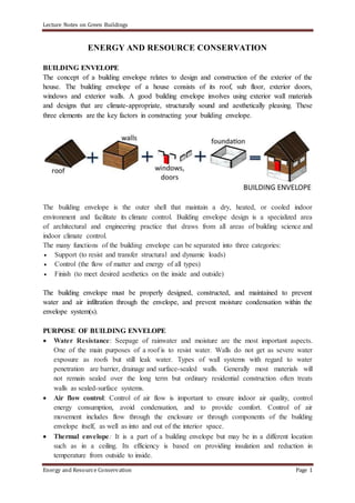
  • 1. Lecture Notes on Green Buildings Energy and Resource Conservation Page 1 ENERGY AND RESOURCE CONSERVATION BUILDING ENVELOPE The concept of a building envelope relates to design and construction of the exterior of the house. The building envelope of a house consists of its roof, sub floor, exterior doors, windows and exterior walls. A good building envelope involves using exterior wall materials and designs that are climate-appropriate, structurally sound and aesthetically pleasing. These three elements are the key factors in constructing your building envelope. The building envelope is the outer shell that maintain a dry, heated, or cooled indoor environment and facilitate its climate control. Building envelope design is a specialized area of architectural and engineering practice that draws from all areas of building science and indoor climate control. The many functions of the building envelope can be separated into three categories:  Support (to resist and transfer structural and dynamic loads)  Control (the flow of matter and energy of all types)  Finish (to meet desired aesthetics on the inside and outside) The building envelope must be properly designed, constructed, and maintained to prevent water and air infiltration through the envelope, and prevent moisture condensation within the envelope system(s). PURPOSE OF BUILDING ENVELOPE  Water Resistance: Seepage of rainwater and moisture are the most important aspects. One of the main purposes of a roof is to resist water. Walls do not get as severe water exposure as roofs but still leak water. Types of wall systems with regard to water penetration are barrier, drainage and surface-sealed walls. Generally most materials will not remain sealed over the long term but ordinary residential construction often treats walls as sealed-surface systems.  Air flow control: Control of air flow is important to ensure indoor air quality, control energy consumption, avoid condensation, and to provide comfort. Control of air movement includes flow through the enclosure or through components of the building envelope itself, as well as into and out of the interior space.  Thermal envelope: It is a part of a building envelope but may be in a different location such as in a ceiling. Its efficiency is based on providing insulation and reduction in temperature from outside to inside.
  • 2. Lecture Notes on Green Buildings Energy and Resource Conservation Page 2 Types of Building envelopes  Dual stage and  Single stage  Dual Stage: A dual-stage system includes a primary barrier with a secondary waterproofing system. An example of a dual-stage system is a brick masonry veneer wall. The brick veneer is the primary barrier, but because water readily migrates through masonry, a secondary waterproofing membrane and flashing system are provided to capture and divert water back to the exterior. If weep holes (openings in the masonry to allow water to drain) are covered with sealant, water can back up in the cavity behind the brick, potentially causing more problems. Fig: Brick masonry veneer wall  Single-stage system: It relies on the exterior “skin” to prevent leakage without a secondary system to manage water leakage. Examples of single-stage systems are roof membranes and insulated metal panels. In single-stage systems, any water leakage (or condensation) behind the exterior skin typically becomes trapped and prematurely deteriorates the system. Regardless of the type of system, flashing must be reliably integrated to prevent or capture and manage leakage.
  • 3. Lecture Notes on Green Buildings Energy and Resource Conservation Page 3 Fig: Single stage system For new buildings, unreliable building envelopes can allow water leakage from the beginning, requiring significant effort to correct deficient components. For existing buildings, as maintenance is deferred, water infiltration into the wall system can go unnoticed for long periods of time, with building components continuing to deteriorate. With construction costs increasing annually and the amount and extent of deterioration multiplying, the cost of a comprehensive building envelope restoration project significantly increases. Provision of Insulation materials is essential in the wall of building to reduce heat transfer from outside to inside. Fig: Wall insulation Fig: Wall insulation PASSIVE ENERGY SYSTEMS Passive energy systems operate without the reliance on external devices. Rather, such as in greenhouses, solariums and sunrooms, solar energy captures sunbeams through glass windows that absorb and retain heat. Passive solar systems include these features:  Passive collectors usually rely on south-facing windows to convert rays into sunlight.  Design of passive solar collectors is based on the law of thermodynamics, which posits that heat transfers from warm to cool surfaces, such as through convection.  The success of the passive solar system depends on its orientation and the thermal mass of its walls, which determine its ability to absorb heat.
  • 4. Lecture Notes on Green Buildings Energy and Resource Conservation Page 4 Examples: Building a well designed, passive solar house can mean comfort in both summer and winter, with minimal energy inputs. On the hottest day of summer, it’s comfortable and cool inside. On the coldest night of the year, passively collected solar heat warms your bones. In temperate climates, the summer days are hot but most nights are cool. And the winter nights are cold, while the winter days often bring some sun. All these factors can be utilized to create a comfortable home all year round. Primary to temperate passive house design is three big factors: good insulation, good thermal mass, and good solar gain. Fig: Passive solar energy house Fig: Elements of Passive solar energy  Good insulation: placed on the outer layer of the house walls and also in the roof cavity, to stop heat entering or leaving the house. This might be in the form of straw bale walls, light earth, or some other insulative materials.  Good thermal mass: this goes on the inside of the house, to store heat – thick earth render on the inside of walls, internal mud brick walls, earth, mud brick or stone floors, and so on.  Solar gain: the side of the house that faces the equator (north, here in Australia) is the warm side in winter and should have the majority of the windows. This will allow lots of solar energy to enter the building in the winter, and this basic premise can be used to lower winter energy costs.
  • 5. Lecture Notes on Green Buildings Energy and Resource Conservation Page 5 In winter, the nights are properly cold, with slightly warmer days that are sometimes sunny. This is the season of creating the blanket effect. In short, the aim in winter is to collect and store heat energy in the house, and let it out as little as possible.  Catching heat: The most passive way to catch heat energy is to utilize the sun, with good house design. Big equatorial facing windows allow the low winter sun to shine into the house and onto the floor and interior walls. Well-designed eave angles support this by letting the lower sun into the equatorial side of the house in winter, but not in summer when the sun is high. A glasshouse on the equatorial side of a building, which opens into the main space, will further enhance this effect. Solar energy is caught and the warmed air escapes into the main house, warming it considerably. Wood stoves are another effective aspect for winter heating, especially if they’re also cooking your food and heating your water, as well as warming the house. If fuelled by sustainably harvested firewood, they’re another form of regenerative + effective energy.  Storing heat: This is where the internal thermal mass of the house comes in – day after day, the thermal mass of the internal walls and floor slowly but surely absorb all that heat. Over time, this builds up to be a considerable heat bank that ‘gives back’ on a 24 hour basis, little by little. Completely passive heating. The insulation’s job is to prevent that heat escaping – the outside walls and the roof space must surround and store this internal pocket of heat, like a blanket. Active Energy Systems Active solar heating systems use solar energy to heat a fluid -- either liquid or air -- and then transfer the solar heat directly to the interior space or to a storage system for later use. If the solar system cannot provide adequate space heating, an auxiliary or back-up system provides the additional heat. Liquid systems are more often used when storage is included, and are well suited for radiant heating systems, boilers with hot water radiators, and even absorption heat pumps and coolers. Both liquid and air systems can supplement forced air systems. Examples: Active solar power setups rely on external energy sources or backup systems, such as radiators and heat pumps to capture, store and then convert solar energy into electricity. Depending on the complexity of the design, it can heat or cool the home or provide power to an entire neighbourhood. Active solar systems include the following features:
  • 6. Lecture Notes on Green Buildings Energy and Resource Conservation Page 6  The collectors are made up of flat-plate PV panels, which are usually mounted and stationary and transfer heat from the solar collector. In advanced designs, panels are often connected with each other to form modules.  Heating water or an antifreeze solution, liquid-based systems circulate the heated liquid through a heat exchanger connected to a storage tank. Air-based systems heat air in a solar air collector and then fans distribute the heated air, circulating it around the home or property as needed for space heating. Energy storage technologies may also be employed with solar heating systems to provide heat when there’s no sunshine, and at night. Energy storage may also be used with solar cooling and solar water heating applications. Fig: Active solar energy system Fig: Solar air heat in buildings Operation  Solar Heating: In the solar PV collector, a heat transfer or "working" fluid such as water, antifreeze (usually non-toxic propylene glycol), or other type of liquid absorbs the solar heat. At the appropriate time, a controller operates a circulating pump to move the fluid through the collector. The liquid flows rapidly, so its temperature only increases 10° to 20°F (5.6° to 11°C ) as it moves through the collector. The liquid flows to either a storage tank or a heat exchanger for immediate use. Heating a smaller volume of liquid to a higher temperature increases heat loss from the collector and decreases the efficiency of the system. Other system components include piping, pumps, valves, an expansion tank, a heat exchanger, a storage tank, and controls.  Storage of Heat: Liquid systems store solar heat in tanks of water that are made up of stainless steel, fiber glass, concrete etc. based on the limits of operating temperature and pressure. In tank type storage systems, heat from the working fluid transfers to a distribution fluid in a heat exchanger exterior to or within the tank. Tanks are pressurized or unpressurized, depending on overall system design. The simplest storage system option is to use standard domestic water heaters. They meet building codes for pressure vessel requirements, are lined to inhibit corrosion, and are easy to install.  Distribution of heat in the room: A radiant floor or a central forced-air system is used to distribute the solar heat. In a radiant floor system, solar-heated liquid circulates through
  • 7. Lecture Notes on Green Buildings Energy and Resource Conservation Page 7 pipes embedded in a thin concrete slab floor, which then radiates heat to the room. Radiant floor heating is ideal for liquid solar systems because it performs well at relatively low temperatures. A carefully designed system may not need a separate heat storage tank, although most systems include them for temperature control. A conventional boiler or even a standard domestic water heater can supply back-up heat. The slab is typically finished with tile. Radiant slab systems take longer to heat the home from a "cold start" than other types of heat distribution systems. Once they start operating, they provide a consistent level of heat. In the forced-air system, a liquid-to-air heat exchanger, or heating coil, is placed in the main room-air return duct before it reaches the furnace. Air returning from the living space is heated as it passes over the solar heated liquid in the heat exchanger. Additional heat is supplied as necessary by the furnace. The coil must be large enough to transfer sufficient heat to the air at the lowest operating temperature of the collector. The two systems that are commonly adopted have their own advantages and disadvantages and are summarized below: Passive energy systems S No Advantages Disadvantages 1 Suitable for a small installation Its efficiency depends on the weather 2 It requires no external equipment, so it’s usually cheaper It has the potential to overheat the buildings, if it is located in a warm climate. 3 It’s better than an active system since it does not rely on radiators or furnaces that dry out the mucous membranes or cause allergies It requires a careful and proper choice in windows for maximum efficiency 4 Reduction in the energy costs Active energy systems S No Advantages Disadvantages 1 No dependence of external weather as heating is through equipment installed The fluids that most efficiently store heat have the potential to release toxic chemicals into the air 2 No release of air emissions in atmosphere High maintenance cost 3 Operation of PV panels for heating Requires expensive external equipment 4 No noise pollution . TYPES OF ENERGY USED IN COMMERCIAL BUILDINGS Systems used:  Electricity, diesel and natural gas
  • 8. Lecture Notes on Green Buildings Energy and Resource Conservation Page 8  Solar and wind energy systems  Biomass and geothermal energy systems Purposes:  Central heating and cooling systems  Electricity and electrical appliances  Hot water and water pumping ENERGY USED IN TRANSPORTATION AND CONSTRUCTION PROCESSES The energy used in building materials and buildings is divided into four categories:  Embodied energy including Energy consumption during building construction: It is non-renewable energy required to initially produce a building and maintain it during its useful life. It includes energy used to acquire, process and manufacture the building materials, including any transportation related to these activities (indirect energy); energy used to transport building products to the site and construct the building (direct energy); and energy consumed to maintain, repair, restore, refurbish or replace materials, components or systems during the life of the building (recurring energy).  Operational Energy: It is the energy is required for heating, cooling, ventilation, lighting, equipment and appliances.  Decommissioning Energy: It is the energy used for demolition/deconstruction of the building and transporting demolished/salvaged materials to landfill/recycling centres. Embodied energy is measured as a quantity of non-renewable energy per unit of building material, component or system. It may be expressed as mega Joules (MJ) or Giga Joules (GJ) per unit of weight (Kg) or area (square meter). Associated environmental impact is implicit in the measure of embodied energy. As a rule of thumb, embodied energy is a reasonable indicator of the overall environmental impact of building material, assemblies or system. Although most of the focus for improving energy efficiency in buildings has been on their operational emissions, it is estimated that about 30% of all energy consumed throughout the lifetime of a building can be in its embodied energy (this percentage varies based on factors such as age of building, climate, and materials). In the past, this percentage was much lower, but as much focus has been placed on reducing operational emissions (such as efficiency improvements in heating and cooling systems), the embodied energy contribution has come much more into play. Energy consumed due to transportation of building materials from initial stage to finished stage and to the site is a part of embodied energy. It is estimated as equivalent to 1.5% of the total embodied energy based on a survey conducted. This figure will naturally increase when return journeys, vehicle manufacture and maintenance and the road network infrastructure are considered. This depends on the state, shape, densities and percentage of truck volume that is filled with the materials that are transported to the site.
  • 9. Lecture Notes on Green Buildings Energy and Resource Conservation Page 9 BUILDING AUTOMATION AND BUILDING MANAGEMENT SYSTEM  Building automation: It is the automatic centralized control of a building's heating, ventilation and air conditioning, lighting and other systems through a building management system or building automation system (BAS).  Building Automation System: It refers to any electrical control system that is used to control a buildings heating, ventilation and air conditioning (HVAC) system. Modern BAS can also control indoor and outdoor lighting as well as security, fire alarms, and basically everything else that is electrical in the building. It is an example of a distributed control system – the computer networking of electronic devices designed to monitor and control the facilities in the building.  Intelligent or smart building: A building controlled by a BAS is often referred to as an intelligent building "smart building", or a "smart home". Objectives of building automation:  Improved occupant comfort  Efficient operation of building systems  Reduction in energy consumption and operating costs  Improved life cycle of utilities Functions of BAS:  Keeping building climate within a specified range  Providing light to rooms based on an occupancy schedule  Monitoring performance and device failures in all systems  Providing malfunction alarms to building maintenance staff  Reducing building energy and maintenance costs compared to a non-controlled building  Regulating operation of energy, air and water conservation measures in the building  Room automation: It is a part of building automation and with a similar purpose. It is the consolidation of one or more systems under centralized control, though in this case in one room. The most common example of room automation is corporate boardroom, presentation suites, and lecture halls, where the operation of the large number of devices that define the room function (such as videoconferencing equipment, video projectors, lighting control systems, public address systems etc.) would make manual operation of the room very complex. It is common for room automation systems to employ a touch screen as the primary way of controlling each operation. BUILDING ACOUSTICS Building acoustics is the science of controlling noise in buildings. This includes the minimisation of noise transmission from one space to another and the control of the characteristics of sound within spaces themselves. Its role is important in the design, operation and construction of most buildings. It shows a significant impact on health
  • 10. Lecture Notes on Green Buildings Energy and Resource Conservation Page 10 and wellbeing, communication and productivity. Its importance can be understood in public spaces such as concert halls, recording studios, lecture theatres etc, where the quality of sound and its intelligibility are very important. Functional elements of sound pollution:  Source  Receiver and  Transmission path. The incident sound from the source will pass through a medium uninterrupted before striking an object. Part of the sound that is released from a source will be transmitted and remaining will be reflected when encountering an obstruction like all or window or roof. In a closed construction, multiple reflections of sound onto the walls and roof result in reflection and reverberation of sound. This results in improper signals at the receiver end. To avoid this problem, sound insulators or absorbers must be kept in the rooms. The sound insulation property of building materials is the ability in the reduction of sound across a partition. Reduction of unwanted sound should be reduced for a comfortable hearing and living environment in the building. Fig: Elements of sound Fig: Sound transmission losses Factors influencing Building acoustics:  The geometry and volume of a space.  The sound absorption, transmission and reflection characteristics of surfaces enclosing the space and within the space.  The sound absorption, transmission and reflection characteristics of materials separating the spaces  The generation of sound inside or outside the space.  Airborne sound transmission.  Impact noise. NOISE OR SOUND CONTROL TECHNIQUES IN BUILDINGS  Techniques based on planning and design
  • 11. Lecture Notes on Green Buildings Energy and Resource Conservation Page 11  Site Planning  Building Design  Methods in Construction  Barriers in Construction Fig: Multiple reflections of sound Fig: Sound reverberation The details are discussed as follows:  Site planning: In this approach, the buildings are arranged on a zone of land that would minimize severe noise impacts. This is done by capitalizing the natural shape as well as contours of the site. One such step is to shield the residential area or other non-sensitive activities from noises by non-residential land, or an open space or by barrier buildings.  Building Design: The height, the room arrangement, the placement of balconies and the windows should be carefully designed and arranged to reduce the sound levels as per the fundamentals of architecture planning.  Method of Construction: The individual elements of buildings can be improved by the variation of structural element materials or internal design to facilitate good sound insulation. This would reduce the noise transmission through wall, windows, doors, ceiling and floors. New soundproofing concepts have been developed which are related to this stage.  Barriers for Construction: Barriers for resisting noise, which is placed in between the sources and receivers. Different types of barriers are possible, like walls, fences made of different materials, planting trees and shrubs in thick, making berms out of earth and combination of individual elements.  Noise Control in transmission of path Noise levels can be controlled through installation of barriers either close to or away from the source. In this method, the traverse length of sound wave increased and hence sound intensity decreased.
  • 12. Lecture Notes on Green Buildings Energy and Resource Conservation Page 12  Noise from Reflection surfaces The reflection of top and side walls or surfaces in the building or room will generate more noise based on multiple reflections of sound waves. Hence insulation materials should be used in rooms where higher sound levels are likely to be generated.  Enclosure to the sound source The sound source enclosed in a paneled structure such as room can reduce the noise levels at the receiver. The actual difference between the sound pressure levels inside and outside an enclosure depends on (i) the transmission loss of the enclosure panels (ii) the acoustic absorption within the enclosure (iii) the panel penetrations which may include windows or doors. Fig: Typical sound insulation systems provided in a building  Miscellaneous measures  Increasing wall mass and the thickness  Using cavity partition in Buildings  Increase of Airspace width of walls  Increasing the Stud Spacing  Usage of Studs in a staggered manner  Studs and panels held together by Resilient Materials  Using different thickness and materials for panels  Using sound absorbing blankets such as rock wool, wood fibers or fiberglass in the airspace  Increase of thickness of glass used in windows  Replacing a hollow core door by a solid door  Avoiding construction of a door in a wall facing direct noise
  • 13. Lecture Notes on Green Buildings Energy and Resource Conservation Page 13  Providing matting using sound insulation material on floor Acoustic Properties of Building Materials The important aspect in controlling acoustics is the selection of appropriate building and insulating materials. The pores or openings, density and nature of material either hard or soft decides the extent of sound transmission through the material. Few details are given as follows:  Masonry, Concrete or Stone Materials: The concrete or stone wall is highly efficient than masonry. Concrete slabs perform relatively better in the sound insulation activity.  Wood and Related Products: These are less dense than masonry. They have a smaller performance in sound isolation. MDF woods and plywood are more effective sound insulators. Wood is used in rooms where perfect sound levels are required. It can reflect, absorb and resonates the sound. Hence it is used in making musical instruments.  Rubber and Plastic: Vinyl, neoprene etc are the common materials used. These materials are used to make low cost economical acoustical devices. But their use is almost considered limited. They can be used as mechanical isolators for floating glass, by preventing vibrations of the diaphragm to be transmitted to the walls. Fig: MDF wood panels Fig: Neoprene sheet  Steel: It is one of the best materials for sound insulation. Because of high cost, it has less application. It is highly dense and massive in nature. Steel carries the sound through vibration within the material.  Glass and Transparent Materials: The glass is massive in nature and is more used in offices and studios for insulation of sound as well as for transparency purposes. It is available in different thicknesses for commercial application. Plexi glass is used to make highly absorption surfaces instead of reflecting.  Other Insulating Materials: Foam, fiber glass, rock wool etc. Are the common materials used as insulators. Fiber glass material gains higher sound absorption property. These materials absorb sound by reducing the velocity of particles that carry the sound waves in the air. Now wood materials absorb more sound at high pressure.
  • 14. Lecture Notes on Green Buildings Energy and Resource Conservation Page 14 Fig: Insulation glass material Fig: Foam material for insulation The approximate reduction of sound levels based on different wall and design conditions of the building are given in the following Table based on Octave band center frequency. Table: Approximate reduction of outside noise provided by typical exterior wall Octave Band Center Frequency (Hz) A B C D E F G H 63 0 9 13 19 14 24 32 21 125 0 10 14 20 20 25 34 25 250 0 11 15 22 26 27 36 30 500 0 12 16 24 28 30 38 37 1,000 0 13 17 26 29 33 42 42 2,000 0 14 18 28 30 38 48 44 4,000 0 15 19 30 31 43 53 45 8,000 0 16 20 30 33 48 58 46 approx. dB(A) 0 12 16 24 27 30 38 33 A: No wall; outside conditions. B: Any typical wall construction,with open windows covering about 5% of exterior wall area. C: Any typical wall construction,with small open air vents of about 1% of exterior wall area, all windows closed. D: Any typical wall construction,with closed but operable windows covering about 10-20% of exterior wall area. E: Sealed glass wall construction,1/4-in glass thickness over approximately 50% of exterior wall area. F: Approximately 20 lb./ft2 solid wall construction with no windows and no cracks or openings. G: Approximately 50 lb/ft2 solid wall construction with no windows and no cracks or openings. H: Any typical wall construction,with closed double windows (panes at least 3/32” thick, air space at least 4 in.) and solid-core gasketed exterior doors VENTILATION SYSTEMS Ventilation is the art of supplying air to a given space and removing exhausted air. The purpose of Ventilation is to supply fresh air and replace exhausted air. The extent of Ventilation required depends upon air changes required to keep CO2 in check, heat dissipation and cooling of human bodies. An adult releases 0.017 m3 per hour of CO2. Air gets contaminated when CO2 levels change from 0.04 % to 0.06% ie., 0.02%. Changes of air
  • 15. Lecture Notes on Green Buildings Energy and Resource Conservation Page 15 due to CO2 contamination is calculated. A poorly designed air conditioning system results in the production of fungi, molds and other sickness causing microbes. Hard Facts • Fresh air contains 21.0% (v/v) O2 • Exhaled air contains 17.0% (v/v) O2 and 83.0 % (v/v) CO2 • An adult emits 45 gm sweat / hour containing bio aerosols. • An adult produces 300 BTU of heat / hour. • Carbon based gaseous pollutants (VOCs) indoors are 2 to 5 times higher than outdoors. • Fresh air is supplied in the room @ 15-30 m3/hour/person in general Natural Ventilation Infiltration: random/ intentional flow of outdoor air through windows, cracks and a variety of openings in the buildings. Exfiltration: movement of air from indoor spaces to outdoor. Provision of deflectors also called as fan lights of 30 cm height at the bottom or top of a window opening inward provides the ventilation of the room even when windows are closed. In case of sloppy roofs, ridge ventilators may be provided. Such ventilators are useful in taking out used vitiated air from large halls.
  • 16. Lecture Notes on Green Buildings Energy and Resource Conservation Page 16 In hot summer months, during day time, hot outside air may be warmer than the inside room air and the ventilators may then reverse their functions. The inside of room will become worse unless the admitted air is cooled down. Arrangements must be made by hanging wet curtains to draw cold air by evaporation. During night time, when temperature falls, all windows and ventilators must be kept open for allowing them to function in a normal manner. Parameters for Natural Ventilation: The air flow occurs mainly due to two driving forces • Pressure Gradient – Difference in outdoor and indoor pressure (varies with building shape, size, openings, wind direction, local environmental densities, neighbour building’s configuration, topography etc.) • Temperature Gradient (Buoyancy Forces)- when the inside air temperature is higher than outside air, the warm air at floor surface starts rising and the cool air starts entering as a result of vacuum created at floor surface. This effect is called as “Stack Effect”. . Limitation of Natural Ventilation • Fairly inefficient as it is not uniformly distributed. • Air doesn’t circulate evenly and stale air gets collected in some dead end spaces. • It brings pollens & other pollutants from outside air. • Maximum energy loss occurs as no conservation of energy can be done Mechanical ventilation It involves use of fans and heating / air conditioning equipments. Principle of mechanical ventilation • Pulling fresh air from outside to indoor spaces. • Exhaust stale air. • Control temperature and humidity inside.
  • 17. Lecture Notes on Green Buildings Energy and Resource Conservation Page 17 INDOOR AIR QUALITY (IAQ) Indoor air quality is improved by appropriate use of building materials and ventilation systems adopted. The following factors affect the IAQ:  Building entrance: The building entrance should be wide enough with surfaces that are energy absorption and high reflection.  Minimum ventilation rates: No artificial ventilation should be required or minimum change of air flow inside the building is required. Outdoor airflow rates should be greater than the indoor air flow requirements.  Usage of less toxic emitting materials: Materials that release high VOCs and toxic emissions either on a short term or long term should be minimized.  Moisture resistant materials: Materials and systems that resist moisture prevent the growth of allergic bacteria and improve indoor air quality.  Thermal comfortable conditions: Personal temperature and airflow control over the HVAC system coupled with a properly designed building envelope will create thermally comfortable and hygienic conditions in the building.  Paints, adhesives and others: Paints, carpets and rubber based products spread lot of VOCs. They cause irritation, allergies and vomiting sensation. Usage of these items that emits less VOCs are preferable. ENERGY EFFICIENT LIGHTING When the energy usage of a product is reduced without affecting its output or final response or user comfort levels is referred as energy efficiency. An energy efficient product consumes less energy to perform the same function when compared to the same product with more energy consumption. Energy efficient lighting involves in replacement (or re-lamping) of traditional lamps (such as incandescent lamps) with that of energy efficient such as fluorescent lamps, CFL lamps and LED lamps. It also incorporates proper lighting controls such as timer controls, PIR and ultrasonic sensors based controls, etc. It includes the turning off lights automatically when they are not in use, especially during daylight. It uses electronic chokes instead of ballasts in case of conventional lighting and also with the use of electronic circuitry; it can achieve dimming of lights when necessary. These energy efficient schemes can be applied for external lighting, internal lighting for residential buildings and internal lighting for commercial buildings. These schemes not only reduce the energy consumption, but also enhance the lighting quality, increase the safety and staff well-being, and reduce the environmental impacts. In industries, energy consumption for lighting constitutes only a small component of the total energy consumed, which is nearly 2-5 percent of total energy consumption. It accounts for 50
  • 18. Lecture Notes on Green Buildings Energy and Resource Conservation Page 18 to 90 per cent in the domestic sector and it may go up to 20-40 percent in case of commercial /building sectors, information technology complexes, and hotels. So it becomes an important area wherein energy to be conserved, especially in the domestic sector. Lighting efficiency solutions therefore play a key role in energy saving opportunities. Hence the energy efficient lighting is necessary  To reduce electricity consumption, thereby reduces the electricity bills  To save electricity rather than wasting in terms of losses  To lower greenhouse emissions because conventional lamps cause CO2 emissions  To achieve peak load reduction Using less electric lighting reduces heat gain, thus saving air-conditioning energy and improving thermal comfort. Electric lighting design also strongly affects visual performance and visual comfort by aiming to maintain adequate and appropriate illumination while controlling reflection and glare. Steps to apply energy efficient lighting  Replacing traditional electrical lamps with energy saving units Energy efficient lamps can deliver the same amount of lighting with greater energy saving at low cost, when compared with conventional lamps. Traditional incandescent lamps consume a lot of energy to produce light in which 90 percent of consumed energy is given off as heat and also they consume more energy, typically 3-5 times more than the actual amount to produce light. Energy efficient lamps overcome these problems by offering many more advantages than incandescent lamps. The two most popular choices of energy efficient light bulbs include CFLs (compact fluorescent lamp) and LED (light emitting diode) lamps. CFLs use 75 percent less energy and produce 75 percent less heat for producing the same amount of illumination as compared with incandescent lamps. They last 10 to 15 times longer and cost 10 to 20 more as compared to incandescent lamps. LED lamps use 75 percent less energy than traditional incandescent and 50 percent less energy than that of a CFL. They can last 8-25 times longer compared to incandescent and up to four times longer than a CFL. Unlike incandescent and CFLs, LED lamps produce no heat and hence they are cool enough to touch. But, these are more expensive; however, they are affordable over the long run. The comparison of these options is given in the Fig. below.
  • 19. Lecture Notes on Green Buildings Energy and Resource Conservation Page 19 Fig: Comparison of conventional vs energy efficient lighting  Improving lighting controls Lighting can be controlled with the use of various sensors to allow the operation of lamps whenever they are needed. These sensors detect the presence of humans, motion, timing or occupancy and based on the sensor output, it switches the lamps ON and OFF. Types of these controls include infrared sensors, automatic timers, motion sensors and dimmers. Passive infrared sensors react to changes in heat, such as the pattern created by a moving person. Ultrasonic sensors transmit sound above the range of human hearing and monitor the time it takes for the sound waves to return. Photo sensors monitor the daylight conditions and accordingly send the signals to main controller to turn the lamps automatically off at dawn and on at dusk. This type of lighting control is commonly used with street lighting and outdoor lighting.  Replacing of Existing Fixtures and Ballasts Replacing energy inefficient accessories with new energy efficient fixtures and ballast gives superior energy savings, longevity, and reliability. The main function of a luminaire or lighting fixture is to distribute, direct and diffuse light. Some fixtures can absorb more than half of the illumination emitted the bulb that reduces the efficiency of the lighting. The higher efficiency fixtures can emit more light and hence one can save
  • 20. Lecture Notes on Green Buildings Energy and Resource Conservation Page 20 energy and money. Such fixtures consist of reflectors to direct the light in a desired direction. All discharge lamps require a ballast (top support cover) for achieving required operation. Conventional magnetic type ballasts cause power losses which is typically 15 percent of the lamp wattage. It also can raise fixture temperature during operation. So the proper ballast must be chosen to reduce ballast losses, fixture temperature and system wattage. In today’s market, many electronic or solid state types of ballast are available which can save 20 to 30 percent energy consumption over standard ballasts.  Using an Automated Device, such as a key tag system, to regulate the Electric Power in a room The key tag system uses a master switch at the entrance of each guest room, requiring the use of a room key-card to activate them. Using this technique, only occupied rooms consume energy because most electrical appliances are switched off when the keycard is removed (when the guest leaves the room). Along with lighting, the heating, air conditioning, radio and television may also be connected to the master switch.  Replacing all Exit signs with Light Emitting Diode (Led) Exit signs LED exit signs are the most expensive, but are also the most efficient exit signs available. They consume only 2 watts compared to 40 watts of incandescent lights. Their payback time is usually about four years.  Using High Intensity Discharge Lighting High intensity discharge (HID) lighting is much more efficient and preferable to incandescent, quartz-halogen and most fluorescent light fixtures. HID types (from least to most efficient) include mercury vapor, metal halide and high pressure sodium. HID lighting is mostly utilized in floodlight, wall pack, canopy, post lantern and area fixtures outdoors. The best type for any application depends on the area being lit and mounting options. WATER CONSERVATION OPTIONS IN BUILDINGS Water usage in buildings depends on the purposes for which it is used such as in cement concrete, curing, watering, drinking water, sanitation purposes etc. The consumption depends on the particular demand of the activity. The water consumed should be minimized to reduce the load of water resources. Following are certain measures to be employed in this aspect: WATER MINIMIZATION IN BUILDING CONSTRUCTIONS  Site water use reduction: Landscape design: Landscape of the area should be properly designed with plants that consume little water for growth. Drip irrigation methods that consume less water may be adopted for lawn development. Provision of 2540% of the plot area with greenery will help improve the aesthetics and improve the local climate.  Building water use reduction:  Plumbing fixtures and fittings such as urinals and WC toilets should be provided with less water consumption fittings.
  • 21. Lecture Notes on Green Buildings Energy and Resource Conservation Page 21  Residential water facilities should be provided with fittings that are leak proof and are of automatic closure after use to avoid wastage. GREY WATER RECYCLING Water consumption in a building depends on many uses (i) domestic use for drinking, cooking, washing, sanitation (ii) development of green belt (iii) for maintaining utility services such as boiler, water treatment plant, etc. The consumed water emerges out as wastewater, which is classified as sullage and sewage. Sullage refers to uncontaminated wastewater from cooking and washing operations contributing to around 60-70% of total wastewater from the houses while sewage refers to the contaminated wastewater coming out from bathrooms that contribute to remaining 30-40% of total wastewater. Sullage is called grey water and sewage is called as dark water. Grey water may contain traces of dirt, food, grease, hair, and certain household cleaning products. While grey water may look “dirty,” it is a safe and even beneficial source of irrigation water in a yard. If recycled properly, grey water can save approximately 70 litres of potable water per person per day in domestic households, therefore grey water recycling is one of a number of water solutions that one should look to in order to decrease wastewater generation. Methods to recycle Grey water  Direct usage to watering plants: Since this water does not contain human contaminated bacteria, it can be easily used for growth of plants in the garden. However, it should not be directly used for growing any fruits or crops without treatment.  Reuse for flushing in WC systems: This can be separated from the sewage and can be used for flushing the WC tanks in buildings. This saves a large amount (20-25 L per flush) of raw water usage.  Recycling after sand filtration: The grey water is allowed in sand filter where inorganic particles like sand, silt and clay greater than the voids of sand are separated. The clean water is collected and can be recycled for flushing or gardening purpose. RAINWATER HARVESTING (RWH) In this method, the rainwater or precipitation falling in a particular area called catchment is collected, stored and used for emergency purposes. A rainwater harvesting system comprises components of various stages - transporting rainwater through pipes or drains, filtration, and storage in tanks for reuse or recharge.
  • 22. Lecture Notes on Green Buildings Energy and Resource Conservation Page 22 Fig: Elements of RWH Fig: Design of RWH pit Components of RWH: Catchment: The area under which rain falls over a surface and contributes to the runoff is called a catchment. In a building, the roof top area is considered as catchment. The runoff flow depends on the percolation of water into the subsoil or floor. Concrete roof will low percolation while loose soil will have high percolation. Conduit: The piping system that diverts rainwater from surface to the collection tank is called conduit. Treatment unit: A RWH treatment unit essentially filters out inorganic particles through filtering action over a multiple beds of gravel, sand and charcoal (See Fig above). The sand allows removal of inorganic particles while the charcoal allows the removal of odor, color and bad gases dissolved in rain water. Storage facility: The water after treatment is collected into a storage tank separately laid for this purpose. The estimate for the capacity of storage tank is calculated as follows: Quantity of rainwater collected over a 10 m x 10 m roof surface experiencing a 1000 mm rainfall = 10 m x 10 m x 1 m = 10 m3 (1000 mm = 1m) Assume 90% of rainwater is collected as runoff = 0.9 x 10 m3 = 9 m3 = 9000 L Assume the stored water is used during a dry period of 60 days or 2 months. Assuming depth as 1 m, Area = 9/1 = 9 m2 Adopting a square tank, size = 3m x 3m. @ 5 lpcd, this is sufficient for 30 people (30 x 5 x 60) for drinking purpose during dry season. RECHARGE PITS Rainwater may be charged into the groundwater aquifers through any suitable structures like dugwells, borewells, recharge trenches and recharge pits. Various recharge structures are possible - some which promote the percolation of water through soil strata at shallower depth (e.g., recharge trenches, permeable pavements) whereas others conduct water to greater depths from where it joins the groundwater (e.g. recharge wells). At many locations, existing structures like wells, pits and tanks can be modified as recharge structures, eliminating the need to construct any structures afresh. A recharge pit is used to manage and store storm water runoff, prevent flooding and downstream erosion, and improve water quality in the area. Recharge pits are small pits of
  • 23. Lecture Notes on Green Buildings Energy and Resource Conservation Page 23 any shape rectangular, square or circular, contracted with brick or stone masonry wall with weep hole at regular intervals. Top of pit can be covered with perforated covers or mesh to block entry of leaves and other unwanted things into the pit. Bottom of pit should be filled with filter media. The capacity of the pit can be designed on the basis of catchment area, rainfall intensity and recharge rate of soil. Usually the dimensions of the pit may be of 1 to 2 m width and 2 to 3 m deep depending on the depth of pervious strata. The pit is filled with 40mm metal, 20 mm metal and coarse sand as given in the figure below. For smaller roof areas, the pits may be filled with broken bricks, pebbles. These pits are suitable for recharging of shallow aquifers, and small houses. RECHARGING OF BORE WELLS WATEWATER RECYCLING: MODULAR SEWAGE TREATMENT PLANTS Sewage from the buildings/houses contains contaminated waste from humans. This can be biologically treated in sewage treatment plants or packaged treatment plants. The conventional sewage treatment plants are larger, costlier and occupy more space. They are operated based on Preliminary, primary, secondary and tertiary treatment systems. The treated wastewater can be disposed off onto land if its BOD< 100 mg/L and TSS < 200 mg/L. The sewage without treatment should not used for farming or gardening as it leads to contamination of resources. Normally, 75-80% of water consumed will be converted to wastewater/sewage. Recycling part of it will reduce the load accordingly on natural water resources. Gated communities and planned developing areas allow provision for wastewater treatment facility and disposing treated sewage for gardening or lawn development. Modular or Package STP’s are innovative and versatile systems for the effective treatment of wastewater, including Nutrient removal. They can be configured for any desired BOD reduction, suspended solids reduction, Ammoniacal and/or total Nitrogen reduction and
  • 24. Lecture Notes on Green Buildings Energy and Resource Conservation Page 24 Phosphorus reduction. They are constructed by combining several stages of conventional design and integrate to obtain the treatment plant designed for the specific purpose that reduces cost and space. Advanced technologies such as Membrane Bio Reactor based treatment plants are being widely used. Advantages:  Lower net annual costs for the plant's period of use  Management and maintenance  High degree of flexibility  High degree of sustainability  Shorter design and construction times; Applications:  Plant modification and expansion  Toilet Flush, Landscape, Car Wash, Construction, Gardening etc.  Apartment Buildings  IT Parks  All Commercial Establishments such as Hospital, Hotels and Educational Institutions Fig: Modular Sewage Treatment Plant Fig: Modular Sewage Treatment Plant WASTE TO ENERGY MANAGEMENT IN RESIDENTIAL COMPLEXES OR GATED COMMUNITIES Energy generation from wastes can be obtained from liquid and solid wastes through recovery of biogas from anaerobic digestion while heat can also be recovered from solid wastes through incineration. Waste generation from residential complexes can be in the form of liquid and solid wastes. The liquid wastes are treated separately based on their quality and contamination levels. Solid wastes generated are mainly municipal solid wastes and hazardous waste or infectious waste depending on the offices that are operated in the building. The liquid waste treatment and its recycling aspects are discussed earlier and now the focus will be on solid waste management. The basic components of solid waste management are generation, collection, treatment, recovery and disposal. Major portion (50-60%) of the solid
  • 25. Lecture Notes on Green Buildings Energy and Resource Conservation Page 25 wastes is food wastes in Indian conditions with moisture content of 40-50%. Remaining wastes are comprised of recyclable material such as paper, plastics, cardboard, textiles, leather, garden trimmings etc. Demolition waste forms a major component in Indian conditions (20-30%). Due to high moisture content, low density, and high amount of demolition wastes, combustion of solid wastes is not a viable option. Biogas generation: The high quantity of biodegradable food wastes can be anaerobically decomposed to biogas (methane + CO2) which can be used for cooking purposes. Different feeds are available for these plants such as vegetable wastes, food wastes, waste food, fruit peelings, animal dung, poultry waste etc. and different materials are available for making biogas digesters such as plastic, masonry, concrete etc. The gas will be collected in a dome that is fixed or floating. The digested sludge can be used as fertilizer. A biogas plant of 2 m3 is sufficient for providing cooking fuel needs of a family of about five persons. Biogas can be used to operate a dual fuel engine to replace up to 80 % of diesel-oil. Diesel engines have been modified to run 100 per cent on biogas. Petrol and CNG engines can also be modified easily to use biogas. Hence, Gated communities and planned developing areas should plan for their own biogas plant and utilize the benefits from the biogas generated. Fig: Biogas plant using cow dung as feed stock Fig: Prefabricated biogas plant 1 m3 Biogas (approx. 6 kWh/m3) is equivalent to: 1. Diesel, Kerosene (approx. 12 kWh/kg) 0.5 kg 2. Wood (approx. 4.5 kWh/kg) 1.3 kg 3. Cow dung (approx. 5 kWh/kg dry matter) 1.2 kg 4. Plant residues (approx. 4.5 kWh/kg d.m.) 1.3 kg 5. Hard coal (approx. 8.5 kWh/kg) 0.7 kg 6. Propane (approx. 25 kWh/m3) 0.24 m3 Advantages  It can produce fuel and electricity when connected to generator  Gives clean fuel without adverse impacts of smokes and related illness.  Availability of power at affordable rates has the following benefits:  Reduces air and solid waste pollution
  • 26. Lecture Notes on Green Buildings Energy and Resource Conservation Page 26  Reduces time wastage while collecting firewood  Reduces reliance on fossil fuels  Lowers fuel import cost  Saves on the environment (Reduces deforestation)  Improves living standards in rural areas.  Reduces global warming  Produces good quality enriched manure to improve soil fertility.  Effective and convenient way for sanitary disposal of organic wastes,  Improving the hygienic conditions. Heat and steam recovery through incineration The solid waste can be heated in an incinerator at high temperatures of 800-1000 C. The heat released through the flue gas can be used to operate a turbine by indirectly heating water in a boiler. The steam turbine is used to generate electricity. The electricity produced will be used for internal energy requirements of the building (see Fig below). However, the incineration will produce air pollutants such as fly ash and flue gases (SO2, NOx etc) that should be treated before they are released into atmosphere. Fig: Incineration of solid waste from energy generation