
Recommandé
Contenu connexe
Tendances
Tendances (20)
En vedette
En vedette (20)
Similaire à Aluminium alloy 6061
Similaire à Aluminium alloy 6061 (20)
Dernier
Dernier (20)
Aluminium alloy 6061
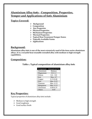
- 1. Aluminium Alloy 6061 - Composition, Properties, Temper and Applications of 6061 Aluminium Topics Covered: Background Composition Key Properties Physical Properties Mechanical Properties Thermal Properties Typical Heat Treatment/Temper States Typically Available Forms Applications Background: Aluminium alloy 6061 is one of the most extensively used of the 6000 series aluminium alloys. It is a versatile heat treatable extruded alloy with medium to high strength capabilities. Composition: Table 1. Typical composition of aluminium alloy 6061 Component Amount (wt.%) Aluminium Balance Magnesium 0.8-1.2 Silicon 0.4 – 0.8 Iron Max. 0.7 Copper 0.15-0.40 Zinc Max. 0.25 Titanium Max. 0.15 Manganese Max. 0.15 Chromium 0.04-0.35 Others 0.05 Key Properties: Typical properties of aluminium alloy 6061 include: Medium to high strength Good toughness Good surface finish
- 2. Excellent corrosion resistance to atmospheric conditions Good corrosion resistance to sea water Can be anodized Good weldability and brazability Good workability Widely available Physical Properties: Density: 2.7 g/cm3 Melting Point: Approx 580°C Modulus of Elasticity: 70-80 GPa Poissons Ratio: 0.33 Mechanical Properties: Temper Ultimate Tensile 0.2% Proof Stress Brinell Hardness Elongation Strength (MPa) (MPa) (500kg load, 10mm 50mm dia (%) ball) 0 110-152 65-110 30-33 14-16 T1 180 95-96 16 T4 179 min 110 min T6 260-310 240-276 95-97 9-13 Thermal Properties: Co-Efficient of Thermal Expansion (20-100°C): 23.5x10⁻⁶ m/m.°C Thermal Conductivity: 173 W/m.K Electrical Properties: Electrical Resistivity: 3.7 – 4.0 x10⁻⁶ Ω.cm Typical Heat Treatment/Temper States: Treatment Definition F As fabricated 0 Annealed to obtain lower strength temper T1 Cooled from an elevated shaping process and naturally aged1 T4, T4511 Solution heat treated and naturally aged2,3 T51 Cooled from an elevated shaping process and artificially aged T6, T6511 Solution heat treated and artificially aged2,3
- 3. Note: This designation applies to products which are not cold worked after cooling from an elevated temperature shaping process, or in which the effect of cold work in flattening or straightening has no effect on mechanical properties This designation applies to products which are not cold worked after solution heat-treated, or in which the effect of cold work in flattening or straightening has no effect on mechanical properties 3. This designation applies to products which are not cold worked after solution heat-treatment, or in which the effect of cold work in flattening or straightening does not effect mechanical properties. Typically Available Forms: Being and extruded grade of aluminium, alloy 6061 is typically available as: Tube Bar Pipe Rod Applications: Typical applications for aluminium alloy 6061 include: Aircraft and aerospace components Marine fittings Transport Bicycle frames Camera lenses Driveshafts Electrical fittings and connectors Brake components Valves Couplings What is the definition of white layer? A thin layer of hardened material caused by a dull insert that gives the false impression of a successful part until the surface fails. Hard turning often requires predicting the wearing of inserts so they can be changed before they cause the white layer.
- 4. (b) (a) Figure 6: A sample without white layer (a), and a sample with white layer (b). Whitelayers formed during machining have negative effects on surface finish and fatigue strength of products. The whitelayer is generally a hard phase and leads to the surface becoming brittle causing crack permeation and product failure. This is a major concern with respect to service performance especially in the aerospace and automotive industries. Numerous authors have investigated the formation of whitelayer under different manufacturing processes. In turning, it was suggested that the whitelayer structure is a martensitic phase whose formation is correlated to tool wear. Past studies have tended to concentrate on the formation of whitelayers at conventional cutting speeds, but never examined the formation at high cutting speeds. Properties: White layer occurs on the surface of steel and may be up to 10 μm thick. The dark layer underneath it may be two or three times thicker. (Ramesh, 2002) The transition between white and dark layer is usually abrupt, and occurs within a transition zone less than 1 μm in depth. (Akcan, Shah et al., 2002) Observation of white layers using a scanning electron microscope and an optical microscope suggest that it has a nanocrystalline structure due to large strain deformation and dynamic recrystallization. It has been proposed that the white layer does not have visible grain boundaries because the grains are small enough that they scatter light—not necessarily because it is resistant to chemical attack. (Akcan, Shah et al., 2002) White layer hardness has been measured to be significantly greater than the martensite in the bulk of the material. (Akcan, Shah et al., 2002) Using nano-indentation hardness measurements, the hardness was found to be approximately 12.85 GPa, compared o about 10.70 GPa for the bulk material. The grain size has been measured between 30-500nm. (Akcan, Shah et al., 2002 ) Formation: The surface of a sample that has been electrodischarge
- 5. machined also has a white layer. White layer has also been observed on surfaces that experience wear, such as on the surface of railroad tracks or a pin-on-disk test. (Griffiths, 1984) White layer is sometimes referred to as untempered martensite, and dark layer is referred to as over tempered martensite, because of their similar properties to heat treatment by models that use heat effects as the primary cause of white layer formation. (Chou andEvans, 1999) In turning, when aggressive cutting parameters are used, even using a new tool, white layer accompanied by tensile stress is expected. This is an unacceptable condition that is typically undesirable. If less aggressive parameters are used with a new tool, one expects no white layer and a compressive residual stress. As the tool wears however, these desirable characteristics diminish and a white layer develops. White layers may form at either low or high cutting speeds. At low speeds it forms due to grain refinement, at high speeds it forms due to rapid heating and quenching. (Akcan, Shah et al., 2002; Ramesh,2002) defects. . Counters EDM "White" Layer effect: The use of Electrical Discharge Machining (EDM)in the production of forming tools to produce plasticsmouldings, die castings, forging dies etc., hasbeen firmly established in recent years. Developmentof the process has produced significant refinementsin operating technique, productivity andaccuracy, while widening the versatility of the process. Electrical Discharge Machining (EDM), while providing a rapid and relatively less expensive means for producing die casting die inserts, at the same time sets up some very high and detrimental surface stresses. These stresses if not completely and properly removed, can accelerate thermal stress cracking. Metal is removed by a series of electrical spark discharges. The steel in the contact area melts or vaporizes then solidifies on the surface of the cavity. Each spark erodes a tiny bit of metal, leaving a small crater in the surface of the tool. This leaves the immediate surface in a high residual tensile stress condition. The topmost or recast "white" layer is a brittle, hard layer prone to cracking. This is the material that has melted and rapidly solidified. The white layer is densely infiltrated with carbon and has a distinct separate structure to that of the parent metal. Below this layer is the heat affected zone that has been structurally altered by the heat produced during EDM. This layer reaches the austenizing temperature of the steel. The zone may contain re-hardened or hard, brittle "untempered" martensite formed during the rapid cooling from the austenizing temperature. This can increase crack susceptibility since this microstructure stores considerable strain energy that decomposes with heat.
- 6. (Reference: www.metallife.com) After mandatory removal, by polishing, of the top "white cast" layer" it is important to protect the next exposed layer. MetaLLife compressive stress removes the scratch stress risers created during polishing and closes the cracks that have propagated below the recast layer into the heat affected "untempered martensite" zone. This restores the desired residual compressive stress benefits to the tool. EDM layer zones* White layer - 5-15 microns - crack prone un tempered - 25-40 microns - crack prone tempered - 40-85 microns 1 micron = 0.00003937" *Depth of zones is dependent on the spark density, volts, and amps of EDM equipment. EDM’s Effect on Surface Integrity: Article From: MoldMaking Technology, Jerry Mercer Posted on: 2/1/2008 Understanding the various layers of a cavity that are thermally altered by the EDM process will help you understand how EDM affects the integrity of the mold surface. Protecting the surface integrity of the cavity is one of the most critical facets of EDM. The integrity of the surface finish in the cavity is determined by the formation of thermally altered layers created by the EDM process, which involves the transference of a controlled electrical discharge between an electrode and the workpiece. The current applied to the workpiece during this discharge melts and vaporizes the metal, creating the thermally altered layers of the cavity. To understand how EDM affects the integrity of the mold
- 7. surface, you must first understand the various layers of the cavity that are thermally altered. EDM changes not only the surface of the work metal, but also the subsurface layers. Thermally Altered Layers: The various layers affected by the EDM process will be referred to as the altered metal zone. Figure 1 shows that the altered metal zone is comprised of two thermally affected sub-layers of material: the recast layer or white layer and the heat affected zone. The white layer is the layer that has been heated to the point of a molten state, but not quite hot enough to be ejected into the gap and be flushed away. The EDM process has actually altered the metallurgical structure and characteristics in this layer as it is formed by the unexpelled molten metal being rapidly cooled by the dielectric fluid during the flushing process and resolidifying in the cavity. This layer does include some expelled particles that have solidified and been re-deposited on the surface prior to being flushed out of the gap. The white layer is densely infiltrated with carbon to the point that its structure is distinctly different than that of the base material. This carbon enrichment occurs when the hydrocarbons of the electrode and dielectric fluid break down during the EDM process and impenetrate into the white layer while the material is essentially in its molten state. The first layer of the heat-affected zone is the re-cast or “white layer”. This layer has been heated above the melting point of the tool
- 8. steel and quickly cooled, subsequently producing an extremely brittle surface subject to micro-cracking. If this condition is left untreated, then propagation of the cracks can ultimately lead to failure of the tool. Immediately below the re-cast layer is the re- hardened layer. This layer has been heated to the austenizing, or hardening temperature and rapidly cooled, leaving an un-tempered brittle surface condition. Below the re- hardened layer is the re-tempered layer. The re-tempered layer has been heated above the normal tempering temperature of the tool steel, leaving the area with a lower hardness than typically useful for the tool. The unaffected base layer is the last layer of the HAZ and this layer is in the same condition as it was prior to the EDM process. Multiple passes using a lower current, on the final passes, can minimize the amount of heat-affected zone, and therefore reduce the chance of the tool cracking while in service. The use of newer EDM equipment, with better control of the amperage and frequency, produce less “white layer”. Removal of the white layer is vital to the longevity of the tool. Grinding or stoning and polishing of the HAZ should be performed on the tool to remove the white layer. Stress relieving of the tool may also reduce the chance of cracking by tempering the re- hardened layer. Stress relieving should be performed about 25-50 degrees F below the last tempering temperature. See the tool steel data sheets for specific tempering temperatures. Influence of machining parameters on the surface integrity in electrical discharge machining: Purpose: The aim of this research is to make a study of the influence of machining parameters on the surface integrity in electrical discharge machining. The material used
- 9. for this study is the X200Cr15 and 50CrV4 steel for dies and moulds, dies castings, forging dies etc. Design/methodology/approach: The methodology consists of the analysis and determination of the white layer thickness WLT, the material removal rate MRR, the electrode wear ratio EWR and the micro hardness of each pulse discharge energy and parameters of electrical discharge machining. Findings: The Results of the tests undertaken in this study show that increasing energy discharge increase instability and therefore, the quality of the workpiece surface becomes rougher and the white layer thickness increases. This is due to more melting and recasting of material.With the increase of the discharge energy, the amount of particles in the gap becomes too large and can form electrically conducting paths between the tool electrode and the workpiece, causing unwanted discharges, which become electric arcs (arcing). these electric arcs damage the electrodes surfaces (tool and workpiece surfaces) and can occur microcracks. Keywords: EDM; Energy discharge; White layer thickness WLT; Metallographic aspect; Cracks; HAZ Reference to this paper should be given in the following way: M. Boujelbene, E. Bayraktar, W. Tebni, S. Ben Salem, Influence of machining parameters on the surface integrity in electrical discharge machining, Archives of Materials Science and Engineering 37/2 (2009) 110-116. Fig. 1. (a) The composition of the heat affected zone HAZ, (b) Influence of the white layer thickness WLT on the discharge energy W in EDM
- 10. Fig. 2. Analyse of the White Layer Thickness WLT as a function of the machined energy W observed under an optical microscope; (a) W = 38.4 J, WLT = 13.7μm; (b) W = 99.84 J, WLT = 18.7μm; (c) W = 384 J, WLT = 31.95μm Fig. 3. The influence of the material removal rate MRR and the electrode wear ratio EWR on the thickness of the white layer.
- 11. Fig. 4. Influence of the tool material on the white layer thickness WLT in roughing EDM; (a) Copper electrode WLT = 53.65 μm, (b) graphite electrode WLT = 51.88 μm Detecting White Layer in Hard Turned Components Using Non-Destructive Methods: Title: Detecting White Layer in Hard Turned Components Using Non-Destructive Methods Author: Harrison, Ian Spencer Abstract: Hard turning is a machining process where a single point cutting tool removes material harder than 45 HRC from a rotating workpiece. Due to the advent of polycrystalline cubic boron nitride (PCBN) cutting tools and improved machine tool designs, hard turning is an attractive alternative to grinding for steel parts within the range of 58-68 HRC, such as bearings. There is reluctance in industry to adopt hard turning because of a defect called white layer. White layer is a hard, 1-5 쭠deep layer on the surface of the specimen that resists etching and therefore appears white on a micrograph. When aggressive cutting parameters are used, even using a new tool, white layer is expected. If more conservative parameters are selected, one does not expect white layer. There is some debate if white layer actually decreases the strength or fatigue life of a part, but nevertheless it is not well understood and therefore is avoided. This research examines the use of two different non-destructive evaluation (NDE) sensors to detect white layer in hard turned components. The first, called a Barkhausen sensor, is an NDE instrument that works by applying a magnetic field to a ferromagnetic metal and observing the induced electrical field. The amplitude of the signal produced by the induced electrical field is affected by the hardness of the material and surface residual stresses. This work also examines the electrochemical properties of white
- 12. layer defects using electrochemical impedance spectroscopy. This idea is verified by measuring the electrochemical potential of surfaces with white layer and comparing to surfaces without any. Further corrosion tests using the electrochemical impedance spectroscopy method indicate that parts with white layer have a higher corrosion rate. The goal of this study is to determine if it is possible to infer white layer thickness reliably using either the Barkhausen sensor or electrochemical impedance spectroscopy (EIS). Measurements from both sensors are compared with direct observation of the microstructure in order to determine if either sensor can reliably detect the presence of white layer. Type: Thesis URI: http://hdl.handle.net/1853/6982 Date: 2005-01-20 Publisher Georgia Institute of Technology Subject: Residual stress White layer Hard turning Barkhausen effect Electrochemical impedance spectroscopy Departm Mechanical Engineering ent: Advisor: Committee Chair: Kurfess, Thomas; Committee Member: Liang, Steven; Committee Member: Melkote, Shreyes Degree: M.S. Title: White layer formation and tool wear in high speed milling of 57HRc tool steel using coated and uncoated tools:
- 13. Author: Paul T. Mativenga, Aamir Mubashar Address: Manufacturing and Laser Processing Research Group, School of Mechanical, Aerospace and Civil Engineering, The University of Manchester, M60 1QD Manchester, UK. ' Manufacturing and Laser Processing Research Group, School of Mechanical, Aerospace and Civil Engineering, The University of Manchester, M60 1QD Manchester, UK Journal: International Journal of Agile Systems and Management 2007 - Vol. 2, No.2 pp. 172 - 185 Abstract: Advances in process technology have opened new possibilities for rapid manufacturing. High Speed Machining (HSM) is one of these innovative areas. One demanding application is the HSM of hardened steels for die and mould tooling applications. A significant impediment in the wide- spread use of HSM in hard machining is a lack of understanding and subsequent control of possible micro-structural changes to the surface of machined components. These changes can occur in the form of surface and sub-surface layers induced by grain refinement, rapid heating and quenching and or reactions with the environment. Some surface layers are known for decreasing the material fatigue life due to their brittleness. Generally, these affected surface layers are referred to as the white layer. This paper focuses on formation of white layers during high speed milling of hardened tool steels. The machining was carried out using uncoated and TiAlCrN coated micro-grain carbide end mills. The cutting tools were also analysed for tool wear. The paper explores the correlation of white layer formation to tool wear progression and how this is affected by the PVD coating. Surface hardening, sub-surface tempering, surface finish and compositional changes are also presented. The results show that in milling, tool wear is a significant driver for white layer thickness progression. Moreover, increased oxygen content suggests that oxidation could also play a role in white layer formation. Keywords: tool coatings; high speed machining; HSM; microhardness; white layer formation; tool wear; high speed milling; tool steels; rapid manufacturing; agile systems; hardened steels; microstructure; carbide end mills; PVD coating; oxidation. DOI: 10.1504/IJASM.2007.015787