SlideShare une entreprise Scribd logo
1  sur  15
FRAMING
The efficiency of any error detection scheme decreases as the length of the data increases. To detect the
errors at the data link layer efficiently and easily, transmitting a small size data is a better approach. Data
link layer (DLL) breaks the datagrams passed down by above layers and convert them into frames ready
for transfer. This is called Framing.
OR
The sream of bits are not advisible to mqaintain in networks. When an error occurs, then the entire stream
have to retransmitted. To avoid this, the framing concept is used. In this, the stream of bits is divided into
manageable bit units called frames. Hence, to provide proper synchronization between sender and
receiver, following framing types came into existence:
a) Character Count :
In this technique, DLL will add characters i.e. count value in the header to specify the number of
characters in the frame.
Disadvantage: In this technique, if the count value is modified by noise then both sender and receiver will
be out of synchronization. Hence this method is rarely used.
b) Character Stuffing :
Flag patterns like FLAG are stuffed between the data to maintain the synchronization between sender and
receiver, hence overcome the drawbacks of Character count.
Special character like ESC is stuffed when there is data pattern equal to the Flag pattern.
(c) Bit Stuffing :
The third method allows data frames to contain an arbitrary number of bits and allows character codes
with an arbitrary number of bits per character. At the start and end of each frame is a flag byte consisting
of the special bit pattern 01111110 .
 Whenever the sender's data link layer encounters five consecutive 1's in the data, it automatically
stuffs a zero bit into the outgoing bit stream. This technique is called bit stuffing.
 When the receiver sees five consecutive 1's in the incoming data stream, followed by a zero bit, it
automatically decodes the 0 bit. The boundary between two frames can be determined by locating
the flag pattern.
Advantage :
In character stuffing, we are stuffing 8 bits , but in bit stuffing we are only stuffing 1 bit. Hence the
overload size is less.
Data Link control
1. Communication requires at least two devices working together, one to send, and one to receive.
Such arrangement requires a great deal of coordination for an intelligible exchange to occur.
For example: In half-duplex transmission, it is essential that only one device transmit at a time. If
both ends of the link puts signal on the line simultaneously, they collide, leaving nothing on the
line but noise.
The coordination of half duplex transmission is part of a procedure called “line discipline”, which
is one of the functions included in the second layer of the OSI model, the data link layer.
2. In addition to line discipline, the most important functions in the data link layer are “flow control”
and “error control”. Collectively, these functions are known as data link control.
3. Line Discipline: Line discipline coordinates the link systems. It determines which device can send
and when it can send. In a network, no device in it should be allowed to transmit until that device
has evidence that the intended receiver is able to receive and is prepared to accept the transmission.
The line discipline functions of the data links layer oversees the establishment of link and the right
of a particular device to transmit at a given time.
Line discipline can be done in two ways:
(a) ENQ/ACK(Enquiry/Acknowledgement)
(b) Poll/Select
ENQ/ACK (Enquiry/Acknowledgement)
1. Enquiry/Acknowledgement (ENQ/ACK) is used primarily in systems where there is no question of
the wrong receiver getting the transmission, that is, when there is a dedicated link between two
devices so that the only device capable of receiving the transmission is the intended one.
2. ENQ/ACK coordinates which device may start a transmission and whether or not the intended
recipient is ready and enabled. Using ENQ/ACK, a session can be initiated by either station on a
link as long as both are of equal rank. For Example: a printer cannot initiate communication with
CPU.
3. In both half-duplex and full-duplex transmission, the initiating device establishes the session. In
half-duplex, the initiator then sends its data while the responder waits. The responder may take
over the link when the initiator is finished or has requested a response. In full-duplex, both devices
can transmit simultaneously once the session has been established.
4. The initiator first transmits a frame called an enquiry (ENQ) asking if the receiver is available to
receive data. The receiver must answer either with an acknowledgement (ACK) frame if it is ready
to receive or with a negative acknowledgement (NAK) frame if it is not.
5. If neither an ACK nor a NAK is received within a specified time limit, the initiator assumes that
the ENQ frame was lost in transmission, disconnects, and sends a replacement. If the response to
the ENQ is negative for three attempts, the initiator disconnects and begins the process again at
another time. If the response is positive, the initiator is free to sends its data. Once all of its data
have been transmitted, the sending system finishes with an end of transmission (EOT) frame.
The following figure shows the above concepts;
Poll/Select
1. The poll select method of line discipline works with topologies where one device is designated as a
primary station and the other device s are secondary stations. Whenever a multipoint link consists
of a primary device and multiple secondary devices using a single transmission line, all exchanges
must be made through the primary device.
2. The primary device controls the link; the secondary devices follow its instructions. It is up to the
primary to determine which device is allowed to use the channel at a given time. If the primary
wants to receive data, it asks the secondaries if they have anything to send; this function is called
polling. If the primary wants to send data, it tells the target secondary to get ready to receive; this
function is called selecting.
3. Poll/select protocols identify each frame as being either to or from a specific device on the link.
Each secondary device has an address that differentiates it from the others. In any transmission,
that address will appear in a specified portion of each frame, called an address or header depending
on the protocol. If the transmission comes from the primary device, the address indicates the
recipient of the data. If the transmission comes from a secondary device, the address indicates the
originator of the data.
4. Select
The select mode is used whenever the primary device has something to send. If it has something to
send, it sends it. Before sending the data, the primary must alert the secondary to the upcoming
transmission and wait for an acknowledgement of the secondary’s ready status.
Before sending data, the primary creates and transmits a select (SEL) frame, one field of which
includes the address of the intended secondary.
5. Multipoint topologies use a single link for several devices. As a frame makes its way down the
link, each of the secondary devices checks the address field. Only when the device recognizes its
own address does it open the frame and read the data. If the secondary is awake and running, it
returns an ACK frame to the primary. The primary then sends one or more data frames, each
addressed to the intended secondary.
The following figure shows the above concepts;
6. Poll
The polling function is used by the primary device to solicit transmission from secondary devices.
The multipoint system guarantees that only one transmission can occur at a time. When the
primary is ready to receive data, it must ask (poll) each device in turn if it has something to send.
When the first secondary is approached, it responds either with a NAK frame if it has nothing to
send or with data if it does.
7. If the response is negative, then primary then polls the next secondary in the same way until it finds
one with data to send. When the response is positive, the primary reads the frame and returns an
acknowledgement (ACK frame) verifying its receipt. The secondary may send several data frames
one after the other or it may required to wait for an ACK before sending each one, depending on
the protocol being used.
8. There are two possibilities for terminating the exchange:
(a) Either the secondary sends all its data, finishing with an end of transmission (EOT) frame.
(b) Or the primary says “times up”.
Which of these occurs depends on the protocol and the length of the message. Once a secondary
has finished transmitting, the primary can poll the remaining devices.
Flow Control:
1. Flow control coordinates the amount of data that can be sent before receiving an acknowledgment
and is one of the most important duties of the data link layer. In most protocols, flow control is a
set of procedures that tells the sender how much data it can transmit before it must wait for an
acknowledgment from the receiver. The flow of data must not be allowed to overwhelm the
receiver. Any receiving device has a limited speed at which it can process incoming data and a
limited amount of memory in which to store incoming data.
2. The receiving device must be able to inform the sending device before those limits are reached and
to request that the transmitting device send fewer frames or stop temporarily. Incoming data must
be checked and processed before they can be used. The rate of such processing is often slower than
the rate of transmission. For this reason, each receiving device has a block of memory, called a
buffer, reserved for storing incoming data until they are processed. If the buffer begins to fill up,
the receiver must be able to tell the sender to halt transmission until it is once again able to receive.
3. Two methods have been developed to control the flow of data across communications link;
(a) Stop-and-wait
(b) Sliding Window
Stop-and-Wait
1. In stop-and-wait method of flow control, the sender waits for an acknowledgement after every
frames it sends. Only when an acknowledgement has been received is the next frame sent. This
process of alternately sending and waiting repeats until the sender transmits an end of transmission
(EOT) frame. The following diagram shows the working of stop-and-wait method.
2. The advantage of stop-and-wait is simplicity; each frame is checked and acknowledged before the
next frame is sent. The disadvantage is inefficiency; stop-and-wait is slow. In other words each
frame is alone on the line. Each frame sent and received uses the entire time needed to traverse the
link. If the distance between devices is long, the time spent waiting for ACKs between each frame
can add significantly to the total transmission time.
Sliding Window
1. In sliding window method of flow control, the sender can transmit several frames before needing an
acknowledgement. Frames can be sent one right after another, meaning that the link can carry several
frames at once and can be used efficiently. The receiver acknowledges only some of the frames, using
a single ACK to confirm the receipt of multiple data frames.
2. The sliding window refers to imaginary boxes at both the sender and the receiver. The window can
hold frames at either end and provides the upper limit on the number of frames that can be transmitted
before requiring an acknowledgement. Frames may be acknowledged at any point without waiting for
the window to fill up and may be transmitted as long as window is not yet full.
3. To keep track of which frames have been transmitted and which received, sliding window introduces
an identification scheme based on the size of the window. The frames are numbered modulo-n, which
means they are numbered from 0 to n-1. For example, if n=8, the frames are numbered 0,1,2,3,4,5,6,7.
4. When the receiver sends an ACK, it includes a number of the next frame it expects to receive. To
acknowledge the receipt of astring of frames ending in frame 4, the receiver sends an ACK containing
the number 5.when the sender sees an ACK with the number 5, it knows that all frames up through
number 4 have been received. The window can hold n-1 frames at either end; therefore a maximum of
n-1 frames may be sent before an acknowledgement is required.
SENDER WINDOW
1. At the beginning of transmission, the sender’s window contains n-1 frames. As frames are sent out, the left
boundary of the window moves inward, shrinking the size of the window. Given a window of size w, if
three frames have been transmitted since the last acknowledgement, then the number of frames left in the
window is w-3. Once an ACK arrives the window expands to allow in a number of new frames equal to the
number of frames acknowledged by that ACK.
2. Given a window of size 7, as shown in the following figure diagram (a)
If frames 0 through 3 have been sent and no acknowledgment has been received, then the sender's window
contains three frames - 4, 5, 6. Now, if an ACK numbered 3 is received by source, it means three frames (0,
1, 2) have been received by receiver and are undamaged. The sender's window will now expand to include
the next three frames in its buffer. At this point the sender's window will contain six frames (4, 5, 6, 7, 0, 1).
(See diagram (b)).
RECEIVER WINDOW
1. At the beginning of transmission, the receiver's window contains not n-1 frames but n-1 spaces for frames.
As the new frames come in, the size of window shrinks. Therefore the receiver window represents not the
number of frames received but the number of frames that may still be received before an ACK must be
sent.
2. Given a window of size w, if three frames are received without an ACK being returned, the number of
spaces in a window is w-3. As soon as acknowledgment is sent, window expands to include places for the
number of frames equal to the number of frames acknowledged.
For example, let the size of receiver's window is 7 as shown in diagram. It means window contains spaces
for 7 frames.
3. With the arrival of the first frame, the receiving window shrinks, moving the boundary from space 0 to 1.
Now, window has shrunk by one, so the receiver may now accept six more frame before it is required to
send an ACK. If frames 0 through 3 have arrived but have not been acknowledged, the window will contain
three frame spaces. As receiver sends an ACK, the window of the receiver expands to include as many new
placeholders as newly acknowledged frames.
4. The window expands to include a number of new frame spaces equal to the number of the most recently
acknowledged frame minus the number of previously acknowledged frame. For e.g., If window size is 7
and if prior ACK was for frame 2 & the current ACK is for frame 5 the window expands by three (5-2). If
the prior ACK was for frame 3 and the current ACK is for frame 1, the window expands by six(1+8-3).
Therefore, the sliding window of sender shrinks from left when frames of data are sending. The sliding window
of the sender expands to right when acknowledgments are received.
The sliding window of the receiver shrinks from left when frames of data are received. The sliding window of
the receiver expands to the right when acknowledgement is sent.
For Example:
The following figure shows a sample transmission that uses sliding window flow control with a window of
seven frames. At the beginning of transmission, both sender and the receiver windows are fully expanded
to include seven frames
ERROR CONTROL
1. In data link layer, the term error control refers to methods of error detection and retransmission.
Automatic Repeat Request (ARQ)
1. Error detection in the data link layer is implemented anytime an error is detected in an exchange, a
negative acknowledgement (NAK) is returnedand the specifiedframes are retransmitted. This process
is called Automatic Repeat request (ARQ).
2. It sometimes happens that a frame is so damaged by noise during transmission that the receiver does
not recognize it as a frame at all. In such cases, ARQ allows us to say that the frame has been lost. A
second function of ARQ is the automatic retransmission of lost frames. Including lost ACK and NAK
frames.
Stop-and Wait ARQ
1. Stop-and-wait ARQ is a form of stop-and-wait flow control extendedto include retransmissionof data
in case of lost or damaged frames. For retransmissionto work, four features are added to basic flow
control mechanism. They are as follows;
(a) The sending device keeps a copy of the last frame transmitted until it receives an acknowledgment for
that frame. Keeping a copy allows the sender to retransmit lost or damaged frames until they are
received correctly.
(b) For identification purposes, both data frames and ACK frames are numbered alternately 0 and 1. A
data 0 frame is acknowledged by an ACK 1 frame, indicating that the receiver has gotten data 0 and is
now expecting data 1. This numbering allows of identification of data frames in case of duplicate
transmission.
(c) If an error is discoveredina data frame, indicating that it has been corrupted in transit, a NAK frame is
returned. NAK frames, which are not numbered, tell the sender to retransmit the last frame sent. Stop-
and-wait ARQ requires that the sender wait until it receives an acknowledgment for the last frame
transmitted before it transmits the next one. When the sending device receives a NAK, it resends the
frame transmitted after the last acknowledgement, regardless of number.
(d) The sending device is equipped with a timer. If an expected acknowledgment is not received within an
allotted time period, the sender assumes that the last data frame was lost in transit and sends it again.
Damaged Frames
1. When a frame is discovered by the receiver to contain an error, it returns a NAK frame and the sender
retransmits the last frame. For example, in the following figure, the sender transmits a data frame: data
0. The receiver returns an ACK 1, indicating that data 0 arrived undamaged and it is now expecting
data 1. The sender transmits its next frame: data 1. It arrives undamaged, and the receiver returns ACK
0. The sender transmits its next frame: data 0. The receiver discovers an error in data 0 and returns a
NAK. The sender retransmits data 0. This time data 0 arrives intact, and the receiver returns ACK 1.
Lost Data Frame: The following figure shows how stop-and-wait ARQ handles the loss of a data frame.
1. The sender is equipped with a timer that starts every time a data frame is transmitted. If the frame
never makes it to the receiver, the receiver can never acknowledge it, positively or negatively. The
sending device waits for an ACK or NAK frame until its timer goes off, at which point it tries again. It
retransmits the last data frame, restarts its timer, and waits for an acknowledgment.
Lost acknowledgement
1. In this case, the data frame has made it to the receiver and has been found to be either acceptable or not
acceptable. But the ACK or NAK frame returned by the receiver is lost in transit. The sending device
waits until its timer goes off, and then retransmits the data frame. The receiver checks the number of
the new data frame. If the lost frame was a NAK, the receiver accepts the new copy and returns the
appropriate ACK.
2. If the lost frame was an ACK, the receiver recognizes the new copy as a duplicate, acknowledges its
receipt, then discards it and waits for the next frame. The following figure shows the concept of stop-
and-wait ARQ, lost ACK frame.
Sliding Window ARQ:
Among the several popular mechanisms for continuous transmission error control, two protocols are
the most popular:
go-back-n ARQ
Selective-reject ARQ, both based on sliding window flow control. To extend sliding window to cover
retransmission of lost or damaged frames, three features are added to the basic flow control
mechanism:
1. The sending device keeps copies of all transmitted frames until they have been acknowledged. If
frames 0 through 6 have been transmitted and the last acknowledgment was for frame 2 the sender
keeps copies of frames 3 through 6 until it knows that they have been received undamaged.
2. In addition to ACK frames the receiver has the option of returning a NAK frame if the data have been
received damaged. The NAK frame tells the sender to retransmit a damaged frame. Because sliding
window is a continuous transmission mechanism both ACK and NAK frames must be numbered for
identification. ACK frame carry the number of next frame expected. NAK frame, on the other hand,
carry the number of the damaged frame itself.
3. Like stop-and-wait ARQ, the sending device in sliding window ARQ is equipped with a timer to
enable it to handle lost acknowledgment. In sliding window ARQ, n – 1 frame (the size of the window)
may be sent before an acknowledgment must be received. By retransmitting the data frames, two
possibilities are covered: lost data and lost NAK. If the lost frame was an ACK frame, the receiver can
recognize the redundancy by the number on the frame and discard the redundant data
Go-Back-n ARQ:
1. In this sliding window go-back-n method. If one frame is lost or damaged, all frames sent since the last
frame acknowledged are retransmitted.
Damaged Frame
1. What if frames 0, 1, 2, and 3 have been transmitted, but the first acknowledgment received is a NAK
3? Remember that a NAK means two things: (1) a positive acknowledgment of all frames received
prior to the damaged frame and (2) a negative acknowledgment of the frame indicated. If the first
acknowledgment is a NAK 3, it means that data frames 0, 1, and 2, were all received in good shape.
Only frame 3 must be resent.
2. What if frames 0 through 4 have been transmittedbeforeaNAK is receivedfor frame 2 As soon as the
receiver discovers an error. It stops accepting subsequent frames until the damaged frame has been
replaced correctly.
3. The following figure gives an example where six frames have been transmitted before an error is
discoveredin frame 3. In this case, an ACK 3 has beenreturnedtelling the sender that frame 0, 1 and 2
have all been accepted. In the figure, the ACK 3 is sent before data 3 has arrived. Data 3 is discovered
to be damaged, so a NAK 3 is sent immediately and frame 4 and 5 are discarded as they in. The
sending device retransmits all three frames (3,4 and 5)and the process continues.
Lost Data frame:
1. Sliding window protocols require that data frames be transmitted sequentially. If one or more frames
are so noise corrupted that they become lost in transit, the next frame to arrive at the receiver will be
out of sequence. The receiver checks the identifyingnumber on each frame, discovers that one or more
have been skipped, and returns a NAK for the first missing frame. A NAK frame does not indicate
whether the frame has been lost or damaged, just that it needs to be resent. The sending device then
retransmits the frame indicated by the NAK as well as any frames that it had transmitted after the lost
one.
2. In the following figure, Data 0 and data 1 arrive intact but data 2 is lost. The next frame to arrive at the
receiver is data 3. The receiver is expectingdata 2 and so considers data3 to be an error, discards it and
returns a NAK 2, indicating the 0 and 1 have been accepted but 2 is in error (in this case lost).
In this example, because the sender has transmitted data 4before receiving the NAK2, data 4 arrives at
the destination out of sequence and is therefore discarded. Once the sender receives the NAK 2, it
retransmits all three pending frames (2, 3 and 4).
Lost Acknowledgement:
1. The sender is not expecting to receive an ACK frame for every data frame it sends. It cannot use the
absence of sequential ACK numbers to identify lost ACK or NAK frames. Instead, it uses a timer. The
sending device can send as many frames as the window allows before waiting for an acknowledgment.
Once that limit has been reached or the sender has no more frames to send, it must wait. If the ACK
(or, especially, if the NAK) sent by the receiver has been lost, the sender could wait forever. To avoid
tying up both devices, the sender is equipped with a timer that begins counting whenever the window
capacity is reached. If an acknowledgment has not been received within time limit, the sender
retransmits every frame transmitted.
2. The following figure shows a situation in which the sender has transmitted all of its frames and is
waiting for an acknowledgement that has been lost along the way. The sender waits a predetermined
amount of time, and then retransmits the unacknowledged frames. The receiver recognizes that the new
transmission is a repeat of the earlier one, sends another ACK, and discards the redundant data.
Selective-Reject ARQ:
In selective-reject ARQ, only the specific damaged or lost frame is retransmitted. If a frame is corrupted in
transit, a NAK is returned and the frame is resent out of sequence. The receiving device must be able to sort
the frames it has and insert the retransmitted frame into its proper place in the sequence. To make such
selectivity possible, a selective reject ARQ system differs from a go-back-n ARQ system in the following
ways.
1. The receivingdevice must containsortinglogic to enable it to reorder frames receivedout of sequence.
It must also be able to store frames received after a NAK has been sent until the damaged frame has
been replaced.
2. The sending device must contain a searching mechanism that allows it to find and select only the
requested frame for retransmission.
3. A buffer in the receiver must keepall previouslyreceivedframes onhold until all retransmissions have
been sorted and any duplicate frames have been identified and discarded.
4. To aid selectivity, ACK numbers, like NAK numbers, must refer to the frame received(or lost) instead
of the next frame expected.
5. This complexityrequires asmaller window size than is neededby the go-back-nmethod if it is to work
efficiently. It is recommended that the window size be less than or equal to (n+1)/2, where n-1 is the
go-back-n window size.
Damaged Frames:
1. The following figure shows a situation in which a damaged frame is received. As we can see, frames 0
and frame 1 received but not acknowledged. Data 2 arrives and is found to contain an error NAK is
returned. Like NAK frames in go-back-n error correction a NAK Here both acknowledges the intact
receipt of any previously unacknowledged data frames and indicates an error in the current frame. In
the figure, NAK 2 tells the sender that data 0 and data 1 have been accepted, but data 2 must be resent.
2. Unlike the receiver ina go-back-nsystem, however, the receiver ina selective-reject system continues
to accept new frames while waiting for an error to be corrected. In the following figure, the receiver
accepts data 3,4 and 5 while waiting for a new copy of data 2. When the new data 2 arrives an ACK 5
can be returned acknowledging the new data 2 and the original frames 3, 4 and 5.
Quite a bit of logic is requiredby the receiver to sort out-of-sequenceretransmissions and to keep track
of which frames are still missing and which have yet to be acknowledged.
Lost Frames:
1. Although frames can be accepted out of sequence, they cannot acknowledge out of sequence. If a
frame is lost, the next framed will arrive out of sequence. When the receiver tries to reorder the
existing frames to include it, it discovers the discrepancy and return NAK.
Lost Acknowledgement:
1. Lost ACK and NAK frames are treated by selective ARQ just as they are by go-back-n ARQ. When
the sending device reaches either capacityof its window or the end of its transmission, it sets atimer. If
no acknowledgment arrives in the time allotted, the sender retransmits all of the frames that remain
unacknowledged. In most cases, the receiver will recognize any duplication and discard them.

Contenu connexe

Tendances (20)

Computer networks - Channelization
Computer networks - ChannelizationComputer networks - Channelization
Computer networks - Channelization
 
data link layer to print
data link layer to printdata link layer to print
data link layer to print
 
Data Link Layer
Data Link Layer Data Link Layer
Data Link Layer
 
Unit 1
Unit 1Unit 1
Unit 1
 
transport layer
transport layertransport layer
transport layer
 
data-link layer protocols
data-link layer protocols  data-link layer protocols
data-link layer protocols
 
Unit 2
Unit 2Unit 2
Unit 2
 
Data link layer
Data link layerData link layer
Data link layer
 
Computer network coe351- part4- final
Computer network coe351- part4- finalComputer network coe351- part4- final
Computer network coe351- part4- final
 
Dcn ppt on data link layer
Dcn ppt on data link layerDcn ppt on data link layer
Dcn ppt on data link layer
 
Presentation of computer network on data link layer
Presentation of computer network on data link layerPresentation of computer network on data link layer
Presentation of computer network on data link layer
 
COMPUTER NETWORKS UNIT 2
COMPUTER NETWORKS UNIT 2COMPUTER NETWORKS UNIT 2
COMPUTER NETWORKS UNIT 2
 
PCCN DATA LINK LAYER UNIT 4 NOTES
PCCN DATA LINK LAYER UNIT 4 NOTESPCCN DATA LINK LAYER UNIT 4 NOTES
PCCN DATA LINK LAYER UNIT 4 NOTES
 
Data Link Layer Numericals
Data Link Layer NumericalsData Link Layer Numericals
Data Link Layer Numericals
 
Data link layer
Data link layerData link layer
Data link layer
 
Cn 317 1
Cn 317 1Cn 317 1
Cn 317 1
 
Computer networking
Computer networkingComputer networking
Computer networking
 
Computer Network - Network Layer
Computer Network - Network LayerComputer Network - Network Layer
Computer Network - Network Layer
 
8251 a basic
8251 a basic8251 a basic
8251 a basic
 
token bus
 token bus token bus
token bus
 

Similaire à Data link control notes

Data communication network ppt_Unit_4.pptx
Data communication network ppt_Unit_4.pptxData communication network ppt_Unit_4.pptx
Data communication network ppt_Unit_4.pptxBHAVYPATEL34
 
Computer Network presention Pravin Bhargav , Surykant Ratrey (1).pptx
Computer Network presention  Pravin Bhargav , Surykant Ratrey (1).pptxComputer Network presention  Pravin Bhargav , Surykant Ratrey (1).pptx
Computer Network presention Pravin Bhargav , Surykant Ratrey (1).pptxPravinbhargav
 
Learning Guide of Determine Best Fit Topology LO 2.pptx
Learning Guide of Determine Best Fit Topology LO 2.pptxLearning Guide of Determine Best Fit Topology LO 2.pptx
Learning Guide of Determine Best Fit Topology LO 2.pptxaytenewbelay1
 
Osi model detail description
Osi model  detail descriptionOsi model  detail description
Osi model detail descriptionBathshebaparimala
 
CN R16 -UNIT-3.pdf
CN R16 -UNIT-3.pdfCN R16 -UNIT-3.pdf
CN R16 -UNIT-3.pdfJoshuaeeda1
 
datalinklayermukesh-150130061041-conversion-gate01.pptx
datalinklayermukesh-150130061041-conversion-gate01.pptxdatalinklayermukesh-150130061041-conversion-gate01.pptx
datalinklayermukesh-150130061041-conversion-gate01.pptxlathass5
 
Computer networks network layer,routing
Computer networks network layer,routingComputer networks network layer,routing
Computer networks network layer,routingDeepak John
 
U2CH1Data Link Layerxxxxxxxxxxxxxxxxx.pptx
U2CH1Data Link Layerxxxxxxxxxxxxxxxxx.pptxU2CH1Data Link Layerxxxxxxxxxxxxxxxxx.pptx
U2CH1Data Link Layerxxxxxxxxxxxxxxxxx.pptxk2w9psdb96
 
Introduction to networking
Introduction to networkingIntroduction to networking
Introduction to networkingIdealGraphics
 

Similaire à Data link control notes (20)

Data communication network ppt_Unit_4.pptx
Data communication network ppt_Unit_4.pptxData communication network ppt_Unit_4.pptx
Data communication network ppt_Unit_4.pptx
 
OSI MODEL.pptx
OSI MODEL.pptxOSI MODEL.pptx
OSI MODEL.pptx
 
Computer Network presention Pravin Bhargav , Surykant Ratrey (1).pptx
Computer Network presention  Pravin Bhargav , Surykant Ratrey (1).pptxComputer Network presention  Pravin Bhargav , Surykant Ratrey (1).pptx
Computer Network presention Pravin Bhargav , Surykant Ratrey (1).pptx
 
Class notes 1
Class notes 1Class notes 1
Class notes 1
 
Data link layer (Unit 2).pdf
Data link layer (Unit 2).pdfData link layer (Unit 2).pdf
Data link layer (Unit 2).pdf
 
DATA LINK LAYER.pdf
DATA LINK LAYER.pdfDATA LINK LAYER.pdf
DATA LINK LAYER.pdf
 
computer network
computer networkcomputer network
computer network
 
Learning Guide of Determine Best Fit Topology LO 2.pptx
Learning Guide of Determine Best Fit Topology LO 2.pptxLearning Guide of Determine Best Fit Topology LO 2.pptx
Learning Guide of Determine Best Fit Topology LO 2.pptx
 
DLL
DLLDLL
DLL
 
Computer network
Computer networkComputer network
Computer network
 
Osi model detail description
Osi model  detail descriptionOsi model  detail description
Osi model detail description
 
CN R16 -UNIT-3.pdf
CN R16 -UNIT-3.pdfCN R16 -UNIT-3.pdf
CN R16 -UNIT-3.pdf
 
CN UNIT II.pptx
CN UNIT II.pptxCN UNIT II.pptx
CN UNIT II.pptx
 
datalinklayermukesh-150130061041-conversion-gate01.pptx
datalinklayermukesh-150130061041-conversion-gate01.pptxdatalinklayermukesh-150130061041-conversion-gate01.pptx
datalinklayermukesh-150130061041-conversion-gate01.pptx
 
Computer networks network layer,routing
Computer networks network layer,routingComputer networks network layer,routing
Computer networks network layer,routing
 
datalinklayermukesh
datalinklayermukeshdatalinklayermukesh
datalinklayermukesh
 
U2CH1Data Link Layerxxxxxxxxxxxxxxxxx.pptx
U2CH1Data Link Layerxxxxxxxxxxxxxxxxx.pptxU2CH1Data Link Layerxxxxxxxxxxxxxxxxx.pptx
U2CH1Data Link Layerxxxxxxxxxxxxxxxxx.pptx
 
Data link layer
Data link layer Data link layer
Data link layer
 
Introduction to networking
Introduction to networkingIntroduction to networking
Introduction to networking
 
Unit 5 : Transport Layer
Unit 5 : Transport LayerUnit 5 : Transport Layer
Unit 5 : Transport Layer
 

Plus de invertis university (10)

Tree
TreeTree
Tree
 
Sorting
SortingSorting
Sorting
 
Program listds
Program listdsProgram listds
Program listds
 
Heaps
HeapsHeaps
Heaps
 
Hashing
HashingHashing
Hashing
 
Dsa book
Dsa bookDsa book
Dsa book
 
B trees
B treesB trees
B trees
 
data structure on bca.
data structure on bca.data structure on bca.
data structure on bca.
 
data structure on bca.
data structure on bca.data structure on bca.
data structure on bca.
 
System security
System securitySystem security
System security
 

Dernier

The basics of sentences session 2pptx copy.pptx
The basics of sentences session 2pptx copy.pptxThe basics of sentences session 2pptx copy.pptx
The basics of sentences session 2pptx copy.pptxheathfieldcps1
 
Measures of Central Tendency: Mean, Median and Mode
Measures of Central Tendency: Mean, Median and ModeMeasures of Central Tendency: Mean, Median and Mode
Measures of Central Tendency: Mean, Median and ModeThiyagu K
 
An Overview of Mutual Funds Bcom Project.pdf
An Overview of Mutual Funds Bcom Project.pdfAn Overview of Mutual Funds Bcom Project.pdf
An Overview of Mutual Funds Bcom Project.pdfSanaAli374401
 
PROCESS RECORDING FORMAT.docx
PROCESS      RECORDING        FORMAT.docxPROCESS      RECORDING        FORMAT.docx
PROCESS RECORDING FORMAT.docxPoojaSen20
 
Key note speaker Neum_Admir Softic_ENG.pdf
Key note speaker Neum_Admir Softic_ENG.pdfKey note speaker Neum_Admir Softic_ENG.pdf
Key note speaker Neum_Admir Softic_ENG.pdfAdmir Softic
 
Grant Readiness 101 TechSoup and Remy Consulting
Grant Readiness 101 TechSoup and Remy ConsultingGrant Readiness 101 TechSoup and Remy Consulting
Grant Readiness 101 TechSoup and Remy ConsultingTechSoup
 
1029 - Danh muc Sach Giao Khoa 10 . pdf
1029 -  Danh muc Sach Giao Khoa 10 . pdf1029 -  Danh muc Sach Giao Khoa 10 . pdf
1029 - Danh muc Sach Giao Khoa 10 . pdfQucHHunhnh
 
Unit-IV; Professional Sales Representative (PSR).pptx
Unit-IV; Professional Sales Representative (PSR).pptxUnit-IV; Professional Sales Representative (PSR).pptx
Unit-IV; Professional Sales Representative (PSR).pptxVishalSingh1417
 
Making and Justifying Mathematical Decisions.pdf
Making and Justifying Mathematical Decisions.pdfMaking and Justifying Mathematical Decisions.pdf
Making and Justifying Mathematical Decisions.pdfChris Hunter
 
Unit-IV- Pharma. Marketing Channels.pptx
Unit-IV- Pharma. Marketing Channels.pptxUnit-IV- Pharma. Marketing Channels.pptx
Unit-IV- Pharma. Marketing Channels.pptxVishalSingh1417
 
Application orientated numerical on hev.ppt
Application orientated numerical on hev.pptApplication orientated numerical on hev.ppt
Application orientated numerical on hev.pptRamjanShidvankar
 
Unit-V; Pricing (Pharma Marketing Management).pptx
Unit-V; Pricing (Pharma Marketing Management).pptxUnit-V; Pricing (Pharma Marketing Management).pptx
Unit-V; Pricing (Pharma Marketing Management).pptxVishalSingh1417
 
Gardella_PRCampaignConclusion Pitch Letter
Gardella_PRCampaignConclusion Pitch LetterGardella_PRCampaignConclusion Pitch Letter
Gardella_PRCampaignConclusion Pitch LetterMateoGardella
 
psychiatric nursing HISTORY COLLECTION .docx
psychiatric  nursing HISTORY  COLLECTION  .docxpsychiatric  nursing HISTORY  COLLECTION  .docx
psychiatric nursing HISTORY COLLECTION .docxPoojaSen20
 
1029-Danh muc Sach Giao Khoa khoi 6.pdf
1029-Danh muc Sach Giao Khoa khoi  6.pdf1029-Danh muc Sach Giao Khoa khoi  6.pdf
1029-Danh muc Sach Giao Khoa khoi 6.pdfQucHHunhnh
 
Holdier Curriculum Vitae (April 2024).pdf
Holdier Curriculum Vitae (April 2024).pdfHoldier Curriculum Vitae (April 2024).pdf
Holdier Curriculum Vitae (April 2024).pdfagholdier
 
Accessible design: Minimum effort, maximum impact
Accessible design: Minimum effort, maximum impactAccessible design: Minimum effort, maximum impact
Accessible design: Minimum effort, maximum impactdawncurless
 

Dernier (20)

The basics of sentences session 2pptx copy.pptx
The basics of sentences session 2pptx copy.pptxThe basics of sentences session 2pptx copy.pptx
The basics of sentences session 2pptx copy.pptx
 
Measures of Central Tendency: Mean, Median and Mode
Measures of Central Tendency: Mean, Median and ModeMeasures of Central Tendency: Mean, Median and Mode
Measures of Central Tendency: Mean, Median and Mode
 
An Overview of Mutual Funds Bcom Project.pdf
An Overview of Mutual Funds Bcom Project.pdfAn Overview of Mutual Funds Bcom Project.pdf
An Overview of Mutual Funds Bcom Project.pdf
 
PROCESS RECORDING FORMAT.docx
PROCESS      RECORDING        FORMAT.docxPROCESS      RECORDING        FORMAT.docx
PROCESS RECORDING FORMAT.docx
 
Key note speaker Neum_Admir Softic_ENG.pdf
Key note speaker Neum_Admir Softic_ENG.pdfKey note speaker Neum_Admir Softic_ENG.pdf
Key note speaker Neum_Admir Softic_ENG.pdf
 
Grant Readiness 101 TechSoup and Remy Consulting
Grant Readiness 101 TechSoup and Remy ConsultingGrant Readiness 101 TechSoup and Remy Consulting
Grant Readiness 101 TechSoup and Remy Consulting
 
1029 - Danh muc Sach Giao Khoa 10 . pdf
1029 -  Danh muc Sach Giao Khoa 10 . pdf1029 -  Danh muc Sach Giao Khoa 10 . pdf
1029 - Danh muc Sach Giao Khoa 10 . pdf
 
Unit-IV; Professional Sales Representative (PSR).pptx
Unit-IV; Professional Sales Representative (PSR).pptxUnit-IV; Professional Sales Representative (PSR).pptx
Unit-IV; Professional Sales Representative (PSR).pptx
 
Código Creativo y Arte de Software | Unidad 1
Código Creativo y Arte de Software | Unidad 1Código Creativo y Arte de Software | Unidad 1
Código Creativo y Arte de Software | Unidad 1
 
Making and Justifying Mathematical Decisions.pdf
Making and Justifying Mathematical Decisions.pdfMaking and Justifying Mathematical Decisions.pdf
Making and Justifying Mathematical Decisions.pdf
 
Unit-IV- Pharma. Marketing Channels.pptx
Unit-IV- Pharma. Marketing Channels.pptxUnit-IV- Pharma. Marketing Channels.pptx
Unit-IV- Pharma. Marketing Channels.pptx
 
INDIA QUIZ 2024 RLAC DELHI UNIVERSITY.pptx
INDIA QUIZ 2024 RLAC DELHI UNIVERSITY.pptxINDIA QUIZ 2024 RLAC DELHI UNIVERSITY.pptx
INDIA QUIZ 2024 RLAC DELHI UNIVERSITY.pptx
 
Application orientated numerical on hev.ppt
Application orientated numerical on hev.pptApplication orientated numerical on hev.ppt
Application orientated numerical on hev.ppt
 
Unit-V; Pricing (Pharma Marketing Management).pptx
Unit-V; Pricing (Pharma Marketing Management).pptxUnit-V; Pricing (Pharma Marketing Management).pptx
Unit-V; Pricing (Pharma Marketing Management).pptx
 
Gardella_PRCampaignConclusion Pitch Letter
Gardella_PRCampaignConclusion Pitch LetterGardella_PRCampaignConclusion Pitch Letter
Gardella_PRCampaignConclusion Pitch Letter
 
psychiatric nursing HISTORY COLLECTION .docx
psychiatric  nursing HISTORY  COLLECTION  .docxpsychiatric  nursing HISTORY  COLLECTION  .docx
psychiatric nursing HISTORY COLLECTION .docx
 
1029-Danh muc Sach Giao Khoa khoi 6.pdf
1029-Danh muc Sach Giao Khoa khoi  6.pdf1029-Danh muc Sach Giao Khoa khoi  6.pdf
1029-Danh muc Sach Giao Khoa khoi 6.pdf
 
Holdier Curriculum Vitae (April 2024).pdf
Holdier Curriculum Vitae (April 2024).pdfHoldier Curriculum Vitae (April 2024).pdf
Holdier Curriculum Vitae (April 2024).pdf
 
Accessible design: Minimum effort, maximum impact
Accessible design: Minimum effort, maximum impactAccessible design: Minimum effort, maximum impact
Accessible design: Minimum effort, maximum impact
 
Mattingly "AI & Prompt Design: The Basics of Prompt Design"
Mattingly "AI & Prompt Design: The Basics of Prompt Design"Mattingly "AI & Prompt Design: The Basics of Prompt Design"
Mattingly "AI & Prompt Design: The Basics of Prompt Design"
 

Data link control notes

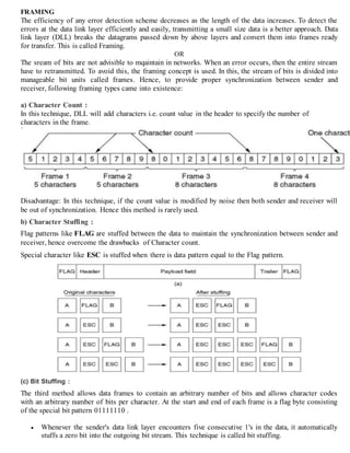
  • 1. FRAMING The efficiency of any error detection scheme decreases as the length of the data increases. To detect the errors at the data link layer efficiently and easily, transmitting a small size data is a better approach. Data link layer (DLL) breaks the datagrams passed down by above layers and convert them into frames ready for transfer. This is called Framing. OR The sream of bits are not advisible to mqaintain in networks. When an error occurs, then the entire stream have to retransmitted. To avoid this, the framing concept is used. In this, the stream of bits is divided into manageable bit units called frames. Hence, to provide proper synchronization between sender and receiver, following framing types came into existence: a) Character Count : In this technique, DLL will add characters i.e. count value in the header to specify the number of characters in the frame. Disadvantage: In this technique, if the count value is modified by noise then both sender and receiver will be out of synchronization. Hence this method is rarely used. b) Character Stuffing : Flag patterns like FLAG are stuffed between the data to maintain the synchronization between sender and receiver, hence overcome the drawbacks of Character count. Special character like ESC is stuffed when there is data pattern equal to the Flag pattern. (c) Bit Stuffing : The third method allows data frames to contain an arbitrary number of bits and allows character codes with an arbitrary number of bits per character. At the start and end of each frame is a flag byte consisting of the special bit pattern 01111110 .  Whenever the sender's data link layer encounters five consecutive 1's in the data, it automatically stuffs a zero bit into the outgoing bit stream. This technique is called bit stuffing.
  • 2.  When the receiver sees five consecutive 1's in the incoming data stream, followed by a zero bit, it automatically decodes the 0 bit. The boundary between two frames can be determined by locating the flag pattern. Advantage : In character stuffing, we are stuffing 8 bits , but in bit stuffing we are only stuffing 1 bit. Hence the overload size is less. Data Link control 1. Communication requires at least two devices working together, one to send, and one to receive. Such arrangement requires a great deal of coordination for an intelligible exchange to occur. For example: In half-duplex transmission, it is essential that only one device transmit at a time. If both ends of the link puts signal on the line simultaneously, they collide, leaving nothing on the line but noise. The coordination of half duplex transmission is part of a procedure called “line discipline”, which is one of the functions included in the second layer of the OSI model, the data link layer. 2. In addition to line discipline, the most important functions in the data link layer are “flow control” and “error control”. Collectively, these functions are known as data link control. 3. Line Discipline: Line discipline coordinates the link systems. It determines which device can send and when it can send. In a network, no device in it should be allowed to transmit until that device has evidence that the intended receiver is able to receive and is prepared to accept the transmission. The line discipline functions of the data links layer oversees the establishment of link and the right of a particular device to transmit at a given time. Line discipline can be done in two ways: (a) ENQ/ACK(Enquiry/Acknowledgement) (b) Poll/Select ENQ/ACK (Enquiry/Acknowledgement)
  • 3. 1. Enquiry/Acknowledgement (ENQ/ACK) is used primarily in systems where there is no question of the wrong receiver getting the transmission, that is, when there is a dedicated link between two devices so that the only device capable of receiving the transmission is the intended one. 2. ENQ/ACK coordinates which device may start a transmission and whether or not the intended recipient is ready and enabled. Using ENQ/ACK, a session can be initiated by either station on a link as long as both are of equal rank. For Example: a printer cannot initiate communication with CPU. 3. In both half-duplex and full-duplex transmission, the initiating device establishes the session. In half-duplex, the initiator then sends its data while the responder waits. The responder may take over the link when the initiator is finished or has requested a response. In full-duplex, both devices can transmit simultaneously once the session has been established. 4. The initiator first transmits a frame called an enquiry (ENQ) asking if the receiver is available to receive data. The receiver must answer either with an acknowledgement (ACK) frame if it is ready to receive or with a negative acknowledgement (NAK) frame if it is not. 5. If neither an ACK nor a NAK is received within a specified time limit, the initiator assumes that the ENQ frame was lost in transmission, disconnects, and sends a replacement. If the response to the ENQ is negative for three attempts, the initiator disconnects and begins the process again at another time. If the response is positive, the initiator is free to sends its data. Once all of its data have been transmitted, the sending system finishes with an end of transmission (EOT) frame. The following figure shows the above concepts; Poll/Select 1. The poll select method of line discipline works with topologies where one device is designated as a primary station and the other device s are secondary stations. Whenever a multipoint link consists of a primary device and multiple secondary devices using a single transmission line, all exchanges must be made through the primary device.
  • 4. 2. The primary device controls the link; the secondary devices follow its instructions. It is up to the primary to determine which device is allowed to use the channel at a given time. If the primary wants to receive data, it asks the secondaries if they have anything to send; this function is called polling. If the primary wants to send data, it tells the target secondary to get ready to receive; this function is called selecting. 3. Poll/select protocols identify each frame as being either to or from a specific device on the link. Each secondary device has an address that differentiates it from the others. In any transmission, that address will appear in a specified portion of each frame, called an address or header depending on the protocol. If the transmission comes from the primary device, the address indicates the recipient of the data. If the transmission comes from a secondary device, the address indicates the originator of the data. 4. Select The select mode is used whenever the primary device has something to send. If it has something to send, it sends it. Before sending the data, the primary must alert the secondary to the upcoming transmission and wait for an acknowledgement of the secondary’s ready status. Before sending data, the primary creates and transmits a select (SEL) frame, one field of which includes the address of the intended secondary. 5. Multipoint topologies use a single link for several devices. As a frame makes its way down the link, each of the secondary devices checks the address field. Only when the device recognizes its own address does it open the frame and read the data. If the secondary is awake and running, it returns an ACK frame to the primary. The primary then sends one or more data frames, each addressed to the intended secondary. The following figure shows the above concepts;
  • 5. 6. Poll The polling function is used by the primary device to solicit transmission from secondary devices. The multipoint system guarantees that only one transmission can occur at a time. When the primary is ready to receive data, it must ask (poll) each device in turn if it has something to send. When the first secondary is approached, it responds either with a NAK frame if it has nothing to send or with data if it does. 7. If the response is negative, then primary then polls the next secondary in the same way until it finds one with data to send. When the response is positive, the primary reads the frame and returns an acknowledgement (ACK frame) verifying its receipt. The secondary may send several data frames one after the other or it may required to wait for an ACK before sending each one, depending on the protocol being used. 8. There are two possibilities for terminating the exchange: (a) Either the secondary sends all its data, finishing with an end of transmission (EOT) frame. (b) Or the primary says “times up”. Which of these occurs depends on the protocol and the length of the message. Once a secondary has finished transmitting, the primary can poll the remaining devices.
  • 6. Flow Control: 1. Flow control coordinates the amount of data that can be sent before receiving an acknowledgment and is one of the most important duties of the data link layer. In most protocols, flow control is a set of procedures that tells the sender how much data it can transmit before it must wait for an acknowledgment from the receiver. The flow of data must not be allowed to overwhelm the receiver. Any receiving device has a limited speed at which it can process incoming data and a limited amount of memory in which to store incoming data. 2. The receiving device must be able to inform the sending device before those limits are reached and to request that the transmitting device send fewer frames or stop temporarily. Incoming data must be checked and processed before they can be used. The rate of such processing is often slower than the rate of transmission. For this reason, each receiving device has a block of memory, called a buffer, reserved for storing incoming data until they are processed. If the buffer begins to fill up, the receiver must be able to tell the sender to halt transmission until it is once again able to receive. 3. Two methods have been developed to control the flow of data across communications link; (a) Stop-and-wait (b) Sliding Window
  • 7. Stop-and-Wait 1. In stop-and-wait method of flow control, the sender waits for an acknowledgement after every frames it sends. Only when an acknowledgement has been received is the next frame sent. This process of alternately sending and waiting repeats until the sender transmits an end of transmission (EOT) frame. The following diagram shows the working of stop-and-wait method. 2. The advantage of stop-and-wait is simplicity; each frame is checked and acknowledged before the next frame is sent. The disadvantage is inefficiency; stop-and-wait is slow. In other words each frame is alone on the line. Each frame sent and received uses the entire time needed to traverse the link. If the distance between devices is long, the time spent waiting for ACKs between each frame can add significantly to the total transmission time. Sliding Window 1. In sliding window method of flow control, the sender can transmit several frames before needing an acknowledgement. Frames can be sent one right after another, meaning that the link can carry several frames at once and can be used efficiently. The receiver acknowledges only some of the frames, using a single ACK to confirm the receipt of multiple data frames. 2. The sliding window refers to imaginary boxes at both the sender and the receiver. The window can hold frames at either end and provides the upper limit on the number of frames that can be transmitted before requiring an acknowledgement. Frames may be acknowledged at any point without waiting for the window to fill up and may be transmitted as long as window is not yet full. 3. To keep track of which frames have been transmitted and which received, sliding window introduces an identification scheme based on the size of the window. The frames are numbered modulo-n, which means they are numbered from 0 to n-1. For example, if n=8, the frames are numbered 0,1,2,3,4,5,6,7. 4. When the receiver sends an ACK, it includes a number of the next frame it expects to receive. To acknowledge the receipt of astring of frames ending in frame 4, the receiver sends an ACK containing the number 5.when the sender sees an ACK with the number 5, it knows that all frames up through number 4 have been received. The window can hold n-1 frames at either end; therefore a maximum of n-1 frames may be sent before an acknowledgement is required.
  • 8. SENDER WINDOW 1. At the beginning of transmission, the sender’s window contains n-1 frames. As frames are sent out, the left boundary of the window moves inward, shrinking the size of the window. Given a window of size w, if three frames have been transmitted since the last acknowledgement, then the number of frames left in the window is w-3. Once an ACK arrives the window expands to allow in a number of new frames equal to the number of frames acknowledged by that ACK. 2. Given a window of size 7, as shown in the following figure diagram (a) If frames 0 through 3 have been sent and no acknowledgment has been received, then the sender's window contains three frames - 4, 5, 6. Now, if an ACK numbered 3 is received by source, it means three frames (0, 1, 2) have been received by receiver and are undamaged. The sender's window will now expand to include the next three frames in its buffer. At this point the sender's window will contain six frames (4, 5, 6, 7, 0, 1). (See diagram (b)). RECEIVER WINDOW 1. At the beginning of transmission, the receiver's window contains not n-1 frames but n-1 spaces for frames. As the new frames come in, the size of window shrinks. Therefore the receiver window represents not the number of frames received but the number of frames that may still be received before an ACK must be sent. 2. Given a window of size w, if three frames are received without an ACK being returned, the number of spaces in a window is w-3. As soon as acknowledgment is sent, window expands to include places for the number of frames equal to the number of frames acknowledged. For example, let the size of receiver's window is 7 as shown in diagram. It means window contains spaces for 7 frames. 3. With the arrival of the first frame, the receiving window shrinks, moving the boundary from space 0 to 1. Now, window has shrunk by one, so the receiver may now accept six more frame before it is required to send an ACK. If frames 0 through 3 have arrived but have not been acknowledged, the window will contain three frame spaces. As receiver sends an ACK, the window of the receiver expands to include as many new placeholders as newly acknowledged frames.
  • 9. 4. The window expands to include a number of new frame spaces equal to the number of the most recently acknowledged frame minus the number of previously acknowledged frame. For e.g., If window size is 7 and if prior ACK was for frame 2 & the current ACK is for frame 5 the window expands by three (5-2). If the prior ACK was for frame 3 and the current ACK is for frame 1, the window expands by six(1+8-3). Therefore, the sliding window of sender shrinks from left when frames of data are sending. The sliding window of the sender expands to right when acknowledgments are received. The sliding window of the receiver shrinks from left when frames of data are received. The sliding window of the receiver expands to the right when acknowledgement is sent. For Example: The following figure shows a sample transmission that uses sliding window flow control with a window of seven frames. At the beginning of transmission, both sender and the receiver windows are fully expanded to include seven frames ERROR CONTROL 1. In data link layer, the term error control refers to methods of error detection and retransmission. Automatic Repeat Request (ARQ) 1. Error detection in the data link layer is implemented anytime an error is detected in an exchange, a negative acknowledgement (NAK) is returnedand the specifiedframes are retransmitted. This process is called Automatic Repeat request (ARQ). 2. It sometimes happens that a frame is so damaged by noise during transmission that the receiver does not recognize it as a frame at all. In such cases, ARQ allows us to say that the frame has been lost. A second function of ARQ is the automatic retransmission of lost frames. Including lost ACK and NAK frames.
  • 10. Stop-and Wait ARQ 1. Stop-and-wait ARQ is a form of stop-and-wait flow control extendedto include retransmissionof data in case of lost or damaged frames. For retransmissionto work, four features are added to basic flow control mechanism. They are as follows; (a) The sending device keeps a copy of the last frame transmitted until it receives an acknowledgment for that frame. Keeping a copy allows the sender to retransmit lost or damaged frames until they are received correctly. (b) For identification purposes, both data frames and ACK frames are numbered alternately 0 and 1. A data 0 frame is acknowledged by an ACK 1 frame, indicating that the receiver has gotten data 0 and is now expecting data 1. This numbering allows of identification of data frames in case of duplicate transmission. (c) If an error is discoveredina data frame, indicating that it has been corrupted in transit, a NAK frame is returned. NAK frames, which are not numbered, tell the sender to retransmit the last frame sent. Stop- and-wait ARQ requires that the sender wait until it receives an acknowledgment for the last frame transmitted before it transmits the next one. When the sending device receives a NAK, it resends the frame transmitted after the last acknowledgement, regardless of number. (d) The sending device is equipped with a timer. If an expected acknowledgment is not received within an allotted time period, the sender assumes that the last data frame was lost in transit and sends it again. Damaged Frames 1. When a frame is discovered by the receiver to contain an error, it returns a NAK frame and the sender retransmits the last frame. For example, in the following figure, the sender transmits a data frame: data 0. The receiver returns an ACK 1, indicating that data 0 arrived undamaged and it is now expecting data 1. The sender transmits its next frame: data 1. It arrives undamaged, and the receiver returns ACK 0. The sender transmits its next frame: data 0. The receiver discovers an error in data 0 and returns a NAK. The sender retransmits data 0. This time data 0 arrives intact, and the receiver returns ACK 1.
  • 11. Lost Data Frame: The following figure shows how stop-and-wait ARQ handles the loss of a data frame. 1. The sender is equipped with a timer that starts every time a data frame is transmitted. If the frame never makes it to the receiver, the receiver can never acknowledge it, positively or negatively. The sending device waits for an ACK or NAK frame until its timer goes off, at which point it tries again. It retransmits the last data frame, restarts its timer, and waits for an acknowledgment. Lost acknowledgement 1. In this case, the data frame has made it to the receiver and has been found to be either acceptable or not acceptable. But the ACK or NAK frame returned by the receiver is lost in transit. The sending device waits until its timer goes off, and then retransmits the data frame. The receiver checks the number of the new data frame. If the lost frame was a NAK, the receiver accepts the new copy and returns the appropriate ACK. 2. If the lost frame was an ACK, the receiver recognizes the new copy as a duplicate, acknowledges its receipt, then discards it and waits for the next frame. The following figure shows the concept of stop- and-wait ARQ, lost ACK frame.
  • 12. Sliding Window ARQ: Among the several popular mechanisms for continuous transmission error control, two protocols are the most popular: go-back-n ARQ Selective-reject ARQ, both based on sliding window flow control. To extend sliding window to cover retransmission of lost or damaged frames, three features are added to the basic flow control mechanism: 1. The sending device keeps copies of all transmitted frames until they have been acknowledged. If frames 0 through 6 have been transmitted and the last acknowledgment was for frame 2 the sender keeps copies of frames 3 through 6 until it knows that they have been received undamaged. 2. In addition to ACK frames the receiver has the option of returning a NAK frame if the data have been received damaged. The NAK frame tells the sender to retransmit a damaged frame. Because sliding window is a continuous transmission mechanism both ACK and NAK frames must be numbered for identification. ACK frame carry the number of next frame expected. NAK frame, on the other hand, carry the number of the damaged frame itself. 3. Like stop-and-wait ARQ, the sending device in sliding window ARQ is equipped with a timer to enable it to handle lost acknowledgment. In sliding window ARQ, n – 1 frame (the size of the window) may be sent before an acknowledgment must be received. By retransmitting the data frames, two possibilities are covered: lost data and lost NAK. If the lost frame was an ACK frame, the receiver can recognize the redundancy by the number on the frame and discard the redundant data Go-Back-n ARQ: 1. In this sliding window go-back-n method. If one frame is lost or damaged, all frames sent since the last frame acknowledged are retransmitted. Damaged Frame 1. What if frames 0, 1, 2, and 3 have been transmitted, but the first acknowledgment received is a NAK 3? Remember that a NAK means two things: (1) a positive acknowledgment of all frames received prior to the damaged frame and (2) a negative acknowledgment of the frame indicated. If the first acknowledgment is a NAK 3, it means that data frames 0, 1, and 2, were all received in good shape. Only frame 3 must be resent. 2. What if frames 0 through 4 have been transmittedbeforeaNAK is receivedfor frame 2 As soon as the receiver discovers an error. It stops accepting subsequent frames until the damaged frame has been replaced correctly. 3. The following figure gives an example where six frames have been transmitted before an error is discoveredin frame 3. In this case, an ACK 3 has beenreturnedtelling the sender that frame 0, 1 and 2 have all been accepted. In the figure, the ACK 3 is sent before data 3 has arrived. Data 3 is discovered
  • 13. to be damaged, so a NAK 3 is sent immediately and frame 4 and 5 are discarded as they in. The sending device retransmits all three frames (3,4 and 5)and the process continues. Lost Data frame: 1. Sliding window protocols require that data frames be transmitted sequentially. If one or more frames are so noise corrupted that they become lost in transit, the next frame to arrive at the receiver will be out of sequence. The receiver checks the identifyingnumber on each frame, discovers that one or more have been skipped, and returns a NAK for the first missing frame. A NAK frame does not indicate whether the frame has been lost or damaged, just that it needs to be resent. The sending device then retransmits the frame indicated by the NAK as well as any frames that it had transmitted after the lost one. 2. In the following figure, Data 0 and data 1 arrive intact but data 2 is lost. The next frame to arrive at the receiver is data 3. The receiver is expectingdata 2 and so considers data3 to be an error, discards it and returns a NAK 2, indicating the 0 and 1 have been accepted but 2 is in error (in this case lost). In this example, because the sender has transmitted data 4before receiving the NAK2, data 4 arrives at the destination out of sequence and is therefore discarded. Once the sender receives the NAK 2, it retransmits all three pending frames (2, 3 and 4).
  • 14. Lost Acknowledgement: 1. The sender is not expecting to receive an ACK frame for every data frame it sends. It cannot use the absence of sequential ACK numbers to identify lost ACK or NAK frames. Instead, it uses a timer. The sending device can send as many frames as the window allows before waiting for an acknowledgment. Once that limit has been reached or the sender has no more frames to send, it must wait. If the ACK (or, especially, if the NAK) sent by the receiver has been lost, the sender could wait forever. To avoid tying up both devices, the sender is equipped with a timer that begins counting whenever the window capacity is reached. If an acknowledgment has not been received within time limit, the sender retransmits every frame transmitted. 2. The following figure shows a situation in which the sender has transmitted all of its frames and is waiting for an acknowledgement that has been lost along the way. The sender waits a predetermined amount of time, and then retransmits the unacknowledged frames. The receiver recognizes that the new transmission is a repeat of the earlier one, sends another ACK, and discards the redundant data. Selective-Reject ARQ: In selective-reject ARQ, only the specific damaged or lost frame is retransmitted. If a frame is corrupted in transit, a NAK is returned and the frame is resent out of sequence. The receiving device must be able to sort the frames it has and insert the retransmitted frame into its proper place in the sequence. To make such selectivity possible, a selective reject ARQ system differs from a go-back-n ARQ system in the following ways. 1. The receivingdevice must containsortinglogic to enable it to reorder frames receivedout of sequence. It must also be able to store frames received after a NAK has been sent until the damaged frame has been replaced. 2. The sending device must contain a searching mechanism that allows it to find and select only the requested frame for retransmission. 3. A buffer in the receiver must keepall previouslyreceivedframes onhold until all retransmissions have been sorted and any duplicate frames have been identified and discarded. 4. To aid selectivity, ACK numbers, like NAK numbers, must refer to the frame received(or lost) instead of the next frame expected.
  • 15. 5. This complexityrequires asmaller window size than is neededby the go-back-nmethod if it is to work efficiently. It is recommended that the window size be less than or equal to (n+1)/2, where n-1 is the go-back-n window size. Damaged Frames: 1. The following figure shows a situation in which a damaged frame is received. As we can see, frames 0 and frame 1 received but not acknowledged. Data 2 arrives and is found to contain an error NAK is returned. Like NAK frames in go-back-n error correction a NAK Here both acknowledges the intact receipt of any previously unacknowledged data frames and indicates an error in the current frame. In the figure, NAK 2 tells the sender that data 0 and data 1 have been accepted, but data 2 must be resent. 2. Unlike the receiver ina go-back-nsystem, however, the receiver ina selective-reject system continues to accept new frames while waiting for an error to be corrected. In the following figure, the receiver accepts data 3,4 and 5 while waiting for a new copy of data 2. When the new data 2 arrives an ACK 5 can be returned acknowledging the new data 2 and the original frames 3, 4 and 5. Quite a bit of logic is requiredby the receiver to sort out-of-sequenceretransmissions and to keep track of which frames are still missing and which have yet to be acknowledged. Lost Frames: 1. Although frames can be accepted out of sequence, they cannot acknowledge out of sequence. If a frame is lost, the next framed will arrive out of sequence. When the receiver tries to reorder the existing frames to include it, it discovers the discrepancy and return NAK. Lost Acknowledgement: 1. Lost ACK and NAK frames are treated by selective ARQ just as they are by go-back-n ARQ. When the sending device reaches either capacityof its window or the end of its transmission, it sets atimer. If no acknowledgment arrives in the time allotted, the sender retransmits all of the frames that remain unacknowledged. In most cases, the receiver will recognize any duplication and discard them.