Télécharger pour lire hors ligne

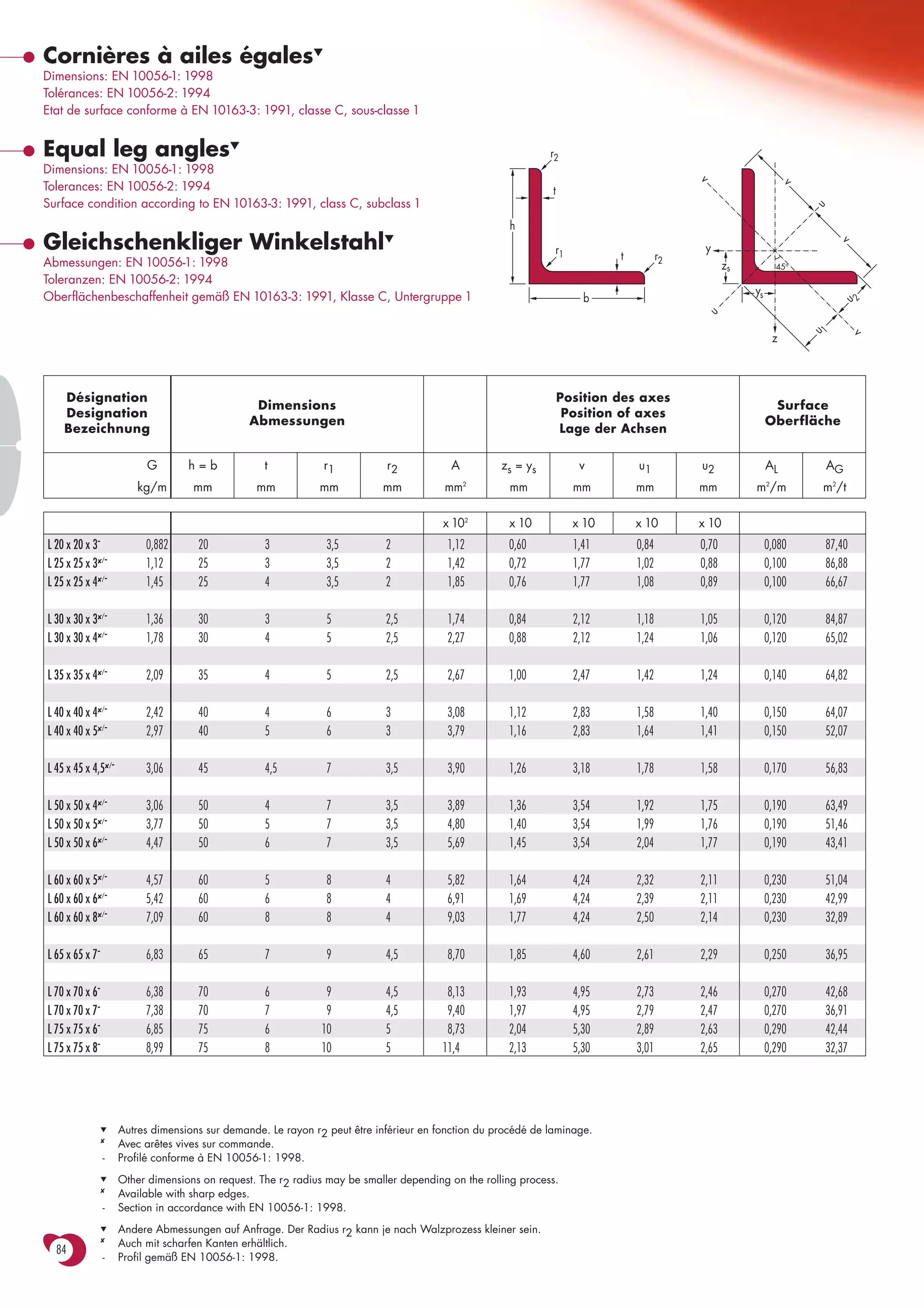
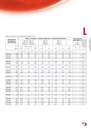
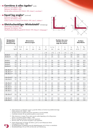

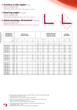
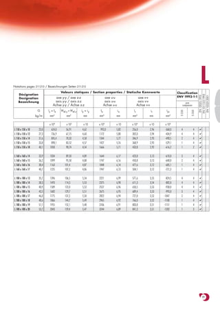
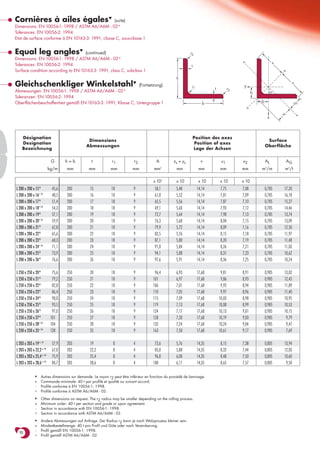
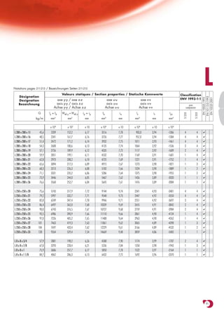
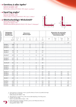
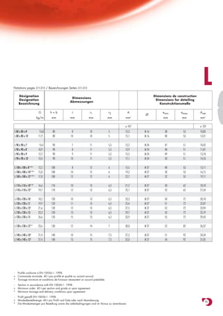
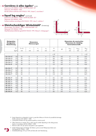
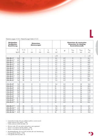
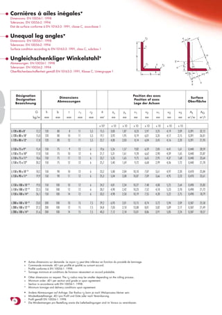
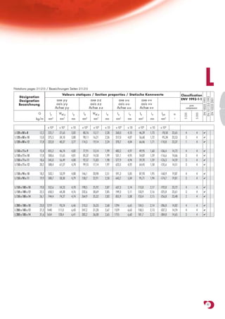
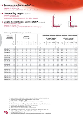

Le document fournit des spécifications techniques pour des cornières à ailes égales, détaillant les dimensions, tolérances et états de surface conformes à différentes normes européennes. Il inclut également des tableaux de propriétés statiques et des désignations d'axes. Des informations sur des dimensions supplémentaires disponibles sur demande sont également mentionnées.


