Télécharger pour lire hors ligne
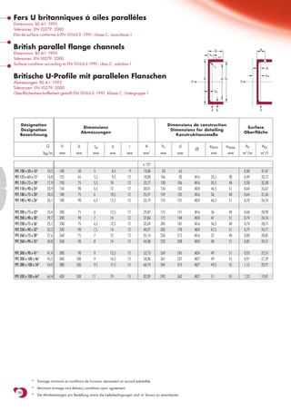
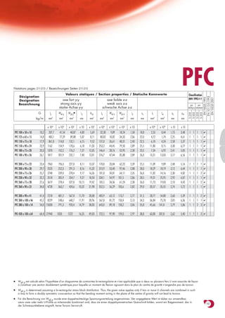

Le document présente des spécifications techniques pour des canaux en U britanniques avec des dimensions et des tolérances conformément aux normes BS et EN. Il inclut des détails sur les propriétés statiques et des valeurs pour différents types de profilés en acier. Les informations comprennent également des notes sur les conditions minimales de tonnage et les exigences de livraison.