Télécharger pour lire hors ligne

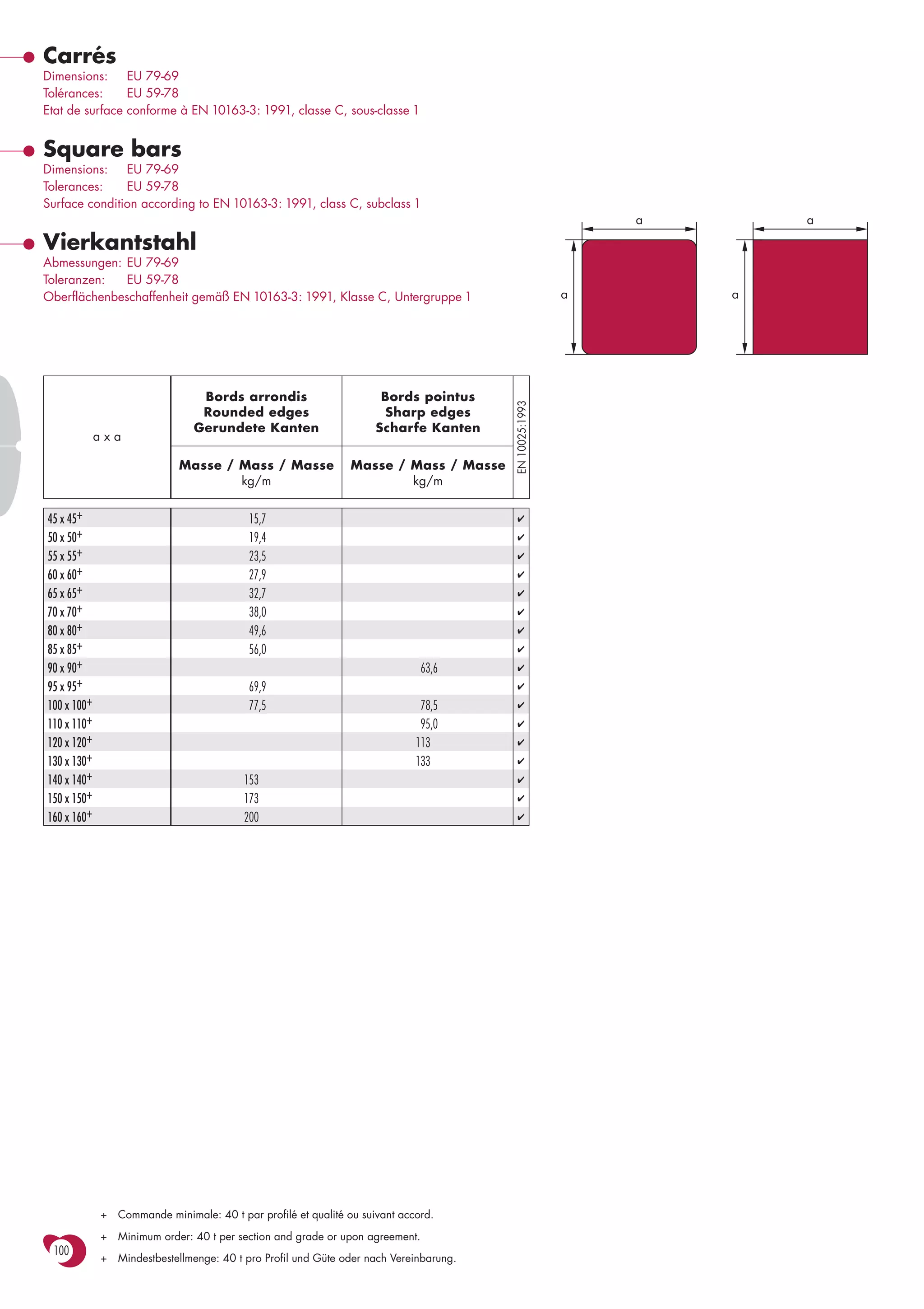

Le document spécifie les dimensions et tolérances des barres carrées, y compris la conformité aux normes EN 10163-3:1991. Il indique également le poids par mètre pour différentes tailles de barres et la quantité minimale de commande. Les exigences sont présentées en plusieurs langues, notamment en français, anglais et allemand.