New 2024 Cannabis Edibles Investor Pitch Deck Template
Principles of rock_blasting
1. Surface Drilling p6-8 23/9/02 7:50 am Page 6
TALKING TECHNICALLY
Principles of Rock Blasting
Combination of
Factors
Blasting by design results from a
large number of factors, all of
which need to be brought under
control in order to achieve the
right result. These include the
choice of drillrig and tools, the
layout of the holes, the explosive,
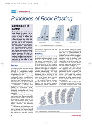
and the skill of the operators. Compression Reflection Gas Pressure
Geology is the governing factor,
and experience is a major ingredi- Figs 1-3 Rock breaking sequence in a normal blast.
ent. Atlas Copco produces drillrigs
and systems to suit all rock types,
and has the experience to recom- calculated, the rock mass will yield and The ratio between spacing and burden
be thrown forward. will have great impact on the blasting
mend the correct approach to all
result, and 1.25 can be considered as
ground conditions in order to
achieve the optimum result. The
Benching an average ratio. The optimum burden
depends upon a number of parame-
following outline of the principles Bench blasting is normally carried out ters, such as rock type, required frag-
involved in rock blasting is a logical by blasting a large number of parallel mentation, type of explosives, hole
start point in the quest for the holes in each round. Considering deviation, and hole inclination.
perfect round. the blasting mechanics, with a com- Nevertheless, as large drill holes can
pression-reflection-gas pressure stage accommodate more explosives, there is
in consecutive order for each charge, it a distinct relationship between burden
Blasting is of vital importance to have a proper and hole diameter (see figure 6).
delay between each row, and even As the bottom part of the blast is
To understand the principles of rock between individual holes in each row. the constricted and critical part for
blasting, it is necessary to start A proper delay will reduce rock throw, successful blasting, it is used as a basis
with the rock fragmentation process improve fragmentation, and limit for deciding all other parameters. The
that follows the detonation of the ground vibrations. The blast should be bottom charge, normally 1.5 x
explosives in a drill hole. planned so that the rock from the first burden, from where the initiation
The explosion is a very rapid row of holes has moved about one should start, requires well packed
combustion, in which the energy con- third of the burden, when the next explosives of higher blasting power
tained in the explosives is released in row is blasted (see figures 4 and 5). than is needed in the column charge
the form of heat and gas pressure. The The horizontal distance between (see figure 7).
transformation acts on the rock in three the hole and the free face is the Stemming of the top part of the
consecutive stages (see figures 1-3). burden, and the parallel distance hole is used to ensure that the energy
Compression: a pressure wave between holes in a row is the spacing. of explosives is properly utilised. It will
propagates through the rock at a
velocity of 2,500–6,000 m/sec,
depending on rock type and type of
explosives. This pressure wave creates
microfractures which promote rock
fracturing.
Reflection: during the next stage,
the pressure wave bounces back from
the free surface, which is normally the
bench wall or natural fissures in the
rock. The compression wave is now
transformed into tension and shear
waves, increasing the fracturing
process.
Gas pressure: large volumes of gas
are released, entering and expanding
the cracks under high pressure. Where
the distance between the blasthole Fig 4 Delay detonation of a typical bench blast.
and the free face has been correctly
6 SURFACE DRILLING
2. Surface Drilling p6-8 23/9/02 7:50 am Page 7
TALKING TECHNICALLY
base type detonation velocity features
m/s
nitro-glycerine dynamite 5500-4500 highly adaptable cartridged
gelatin excellent in smaller holes
ammonium- ANFO 2500 low cost, high safety, easy to
nitrate pour or blow
no water resistance, contains
5-6% fuel oil
Firing pattern
This firing pattern provides separate delay water slurry 4000-3000 watergel basically ANFO made water
time for practically all blastholes and gives resistant gel
good fragmentation as well as good 5000 emulsion stable oil/water emulsion –
breakage in the bottom part of the round. heavy ANFO
packaged or pumpable
Fig 5 Firing sequence in delay blasting. range depends on
storage time
also reduce and control the fly rock Table 1 Features of common types of explosives.
ejected from the blast. This tends to
travel long distances, and is the main
cause of on-site fatalities and damage The propagation velocity varies with Practical hole diameters for bench
to equipment. Dry sand or gravel different kinds of rock, and is reduced drilling range from 30 to 400 mm.
having a particle size of 4 to 9 mm by cracks and fault zones. Hard, homo- Generally, the cost of large diameter
constitutes the ideal stemming material. geneous rocks, with high propagation drilling and blasting is cheaper per
Inclined holes give less back break, velocity, are best fragmented by an cubic metre than using small holes.
safer benches and less boulders, when explosive having high velocity of deto- However, rock fragmentation is
compared to vertical holes. nation (VOD). improved by higher specific drilling.
An extensive range of different The explosive is initiated with deto-
Types of Explosive types and grades of explosives is avail- nators which can be electric or non-
able to suit various blasting applica- electric. Electric systems have the
The geology frequently has more tions. A breakdown is presented in advantage that the complete circuit
effect on the fragmentation than does table 1. can easily be checked with an Ohm-
the explosive used in the blast. The In dry conditions, ANFO has meter to ensure that all connections
properties that influence the result of become the most used blasting agent, and detonators are correct before
the blast are compressive strength, due to its availability and economy. blasting. To eliminate the risk for spon-
tensile strength, density, propagation The blast hole diameter, together taneous ignition from lightning, non-
velocity, hardness and structure. In with the type of explosive used, will electric systems, including detonating
general, rock has a tensile strength determine burden and hole depth. cord, are used.
which is 8 to 10 times lower than
the compressive strength. The tensile
Boulders and flyrock
strength has to be exceeded during
come from this zone
the blast, otherwise the rock will not
break. High rock density requires
more explosives to achieve the
displacement.
Burden as a function of Back break
Drill Hole Diameter Stemming
(length ~ burden)
Practical Values Burden
Column charge
only light charge
needed for good
fragmentation
Subdrilling
Bottom charge = 0,3 burden
Hole Diameter, mm
requires well packed
Spacing Equal to 1,25 Burden high blasting power
Fig 6 Burden as a function of drill hole
diameter. Fig 7 Charging for optimum fragmentation.
SURFACE DRILLING 7
3. Surface Drilling p6-8 23/9/02 7:50 am Page 8
TALKING TECHNICALLY
Hole Deviation In case α is greater than ~15˚ the
hole deflects perpendicularily
Collaring A main factor influencing fragmenta-
misalignment to foliation (bedding).
tion and the overall blasting result, is
Collaring offset that the drill hole follows its designed α
α
path along its entire length. As straight
holes are important, hole deviation
should be avoided as far as possible.
To make the practical outcome cor-
respond to the pre-calculated blasting
results, a first requirement is that the
Planned blast holes are actually drilled as as-
hole sumed in the theoretical pattern. This
means that the holes must be collared in
the exact spot, and drilled in the cor-
rect direction and to the proper depth.
Figure 8 illustrates various causes of Fig 10 Influence of bedding and foliation
hole deviation. Precision in collaring on drilling.
In-hole and hole alignment can be achieved
deviation with proper surveying and mark-ups of
the drill pattern grid, coupled with drill double drill steel support for improved
angle indicator mounted on the feed, visibility and rod guidance. The ROC
Incorrect and hole depth instrument. It is also D-series are furnished with an interme-
depth Due to
collar error essential to have a good view of the diate drill steel support on the feed.
collaring procedure from the operator’s The most severe cause, which is
Fig 8 Various causes of hole deviation. cabin. Atlas Copco equips their modern more difficult to overcome, is the
ROC range of crawler drills with in-hole deviation during drilling, usually
because of geological conditions.
Figures 9 and 10 illustrate the
influence of bedding and foliation.
The drill hole tends to deviate to
a direction perpendicular to the joint-
ing. The longer the holes, the more
accentuated is the deflection. It is often
claimed that the deviation is proportion-
al to the depth to the power of two.
Experience shows that the approach
angle of the drill bit towards the bed-
ding is crucial. There seems to be a
tendency for the bit to follow parallel
to the bedding where the angle of
approach is smaller than 15 degrees.
Drilling through homogeneous
rock, such as isotropic granite with
sparse jointing, causes little, or no, in-
hole deviation.
There are various ways and means
to reduce this problem:
A stiff drill string, and small clear-
ance between the hole and the drill
string components, give straighter
holes. For top hammer drilling, Atlas
Copco provides TAC tubes to be
added behind the bit. The usage of
TAC tubes will improve the flushing
and reduce the risk of getting stuck.
A combination of reduced feed
force and increased rotation speed
gives less deviation.
DTH drilling, COPROD drilling, and
rotary drilling all give less deviation
than top hammer drilling.
Less hole depth, and consequently
low benches, gives better control of
deviation.
Fig 9 Hole deviation in a presplit rock wall.
by Hans Fernberg
8 SURFACE DRILLING