Electro Pneaumatic Breaking system
•Télécharger en tant que DOCX, PDF•
0 j'aime•6,249 vues


Recommandé
Contenu connexe
Tendances
Tendances (20)
En vedette
En vedette (20)
Similaire à Electro Pneaumatic Breaking system
Similaire à Electro Pneaumatic Breaking system (20)
Electro Pneaumatic Breaking system
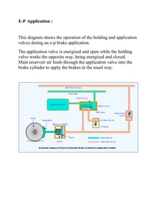
- 1. E-P Application : This diagram shows the operation of the holding and application valves during an e-p brake application. The application valve is energised and open while the holding valve works the opposite way, being energised and closed. Main reservoir air feeds through the application valve into the brake cylinder to apply the brakes in the usual way.
- 2. Brake Cylinder Pressure It is essential to ensure that, during braking, the train wheels do not skid. Skidding reduces the braking capability and it damages wheels and rails. Wheels involved in a skid will often develop "flats", a small flat patch on the tyre which can normally only be removed by reprofiling the wheel in a workshop. To reduce the risk of skidding, brake cylinder pressure must be restricted. In a pure air brake system, a natural restriction is imposed by the maximum allowed brake pipe pressure and in the proportion of volume between the auxiliary reservoir and the brake cylinder. In an e-p equipped train, the main reservoir supply is not restricted, so it would be possible to go on pumping air into the brake cylinder until it burst. Of course, this will not happen because the brake cylinder is fitted with a safety valve (not shown in the diagram) set at the maximum pressure normally obtained in full braking. E-P Brake Release In the "Release" position (diagram left), both electrically operated valves are de-energised, the application valve being closed and the holding valve being open. Once the holding valve is open, brake cylinder air can escape and release the brakes. It is possible to stop the release by energising the holding valve again. This prevents any more brake cylinder air escaping. By adjusting the applications and releases of the brake during the stop, the driver is able to get a very precise stopping position. In addition, the response of the equipment to his commands is instantaneous on every car. This sort of control is essential for a rapid transit service on a metro line with frequent stops, heavy patronage and short headways.
- 3. E-P Brake Release E-P Control:
- 4. Electro-Pneumatic brakes are controlled by the driver's brake valve handle. It is usually the same handle used to control the air brake. Electrical contacts are provided so that selection of a position will energise the train wires required to operate the e-p valves on each car, as shown left. Current to operate the brake control is supplied from a battery through a control switch, which is closed in the operative cab. In the release position, all contacts are open and the e-p valves on each car are de- energised. In the "Application" position, the holding and application contacts are energised and the holding and application valves will be energised on each car to cause the brakes to apply. Note that the contact for the holding wire is arranged to close first so that no air will escape when the application valve is opened. In the "Holding" position, only the holding wire is energised. If this position is selected after an application, the brake cylinder pressure remains at the value reached at that time. If after a partial release, the brake cylinder pressure will remain at the lower value achieved at that time. In effect, the driver can add or subtract air at will and can obtain an infinite variety of braking rates according to the requirements of each stop. In all other positions, only the holding wire is energised. In reality, it is not needed to allow the operation of the air brake but it is closed anyway to act as a back up. E-P Variations There have been a number of developments of the e-p braking system over the years, including a common addition - the "Self Lapping" brake. There have also been "retardation controllers" and, more recently, variable load control and single wire or P-wire control.
- 5. Principles of the E-P Brake There are many types of e-p brake systems is use today and most of them were developed as an "add-on" to the original air brake system and, as a result, incorporated some common principles in their design as follows: The e-p brake operates as the service brake while the air brake is retained for emergency use The e-p brake does not compromise the fail-safe or "vital" features of the air brake The air brake normally remains in the "Release" position, even while the e-p brake is in "Application" and the same brake cylinders are used. E-P brakes are invariably used on multiple unit passenger trains. E-P brakes use a number of train wires to control the electrically operated brake valves on each car. The train wires are connected to a brake "valve" or controller in the driver's cab. E-P brakes should not be confused with ECP (Electronically Controlled Pneumatic) brakes. E-P brakes are used on multiple unit passenger trains whereas ECP brakes have been developed recently for
- 6. use on freight trains. ECP brakes do not always require a train wire and, if they do, it is usually a single wire. A detailed description of an ECP brake system is here.