Pelamis wave energy converter seminar report
•Télécharger en tant que DOCX, PDF•
46 j'aime•18,360 vues

seminar report on renewable source of energy called pelamis wave energy converter,a technology that uses the motion of ocean surface waves to create electricity.bright scope in future and emerging very fastly.

Recommandé
Contenu connexe
Tendances
Tendances (20)
Similaire à Pelamis wave energy converter seminar report
Similaire à Pelamis wave energy converter seminar report (20)
Dernier
Dernier (20)
Pelamis wave energy converter seminar report
- 1. SEMINAR REPORT ON PELAMIS WAVE ENERGY CONVERTER Submitted in partial fullfillment for the award of the degree of Bachelor Of Technology In Mechanical Engineering By SUBMITED BY:-SUBMITED TO:- SUKHRAJ SINGHER. NARENDER BANSAL 1809549ER. RAHUL GARG MECHANICAL ENGG.MECHANICAL DEPTT. Department of Mechanical Engineering HARYANA ENGINEERING COLLEGE JAGADHRI – 135003 (HARYANA)
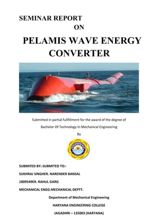
- 2. ABOUT PELAMIS The Pelamis Wave Energy Converter is a technology that uses the motion of ocean surface waves to create electricity. The machine is made up of connected sections which flex and bend as waves pass; it is this motion which is used to generate electricity. Developed by the Scottish company Pelamis Wave Power (formerly Ocean Power Delivery), the Pelamis became the world’s first offshore wave machine to generate electricity into the grid, when it was first connected to the UK grid in 2004. Pelamis Wave Power have since gone on to build and test five additional Pelamis machines. Three, first generation P1 machines which were tested in a farm off the coast of Portugal in 2009 and two of a second generation of machines, the Pelamis P2, which started tests off Orkney in 2010.
- 3. OPERATION The Pelamis machine is an offshore wave energy converter, operating in water depths greater than 50m. The machine consists of a series of semi-submerged cylindrical sections linked by hinged joints. As waves pass along the length of the machine, the sections move relative to one another. The wave-induced motion of the sections is resisted by hydraulic cylinders which pump high pressure oil through hydraulic motors via smoothing hydraulic accumulators. The hydraulic motors drive electrical generators to produce electricity. Electricity from all the joints is fed down a single umbilical cable to a junction on the sea bed. Several devices can be connected and linked to shore through a single seabed cable.
- 4. PRINCIPLES The Pelamis is an attenuating wave energy converter designed with survivability at the fore. The machine's long thin shape and low drag profile minimises hydrodynamic forces, namely inertia, drag, and slamming, which in large waves give rise to large loads. The machine responds to the curvature of the waves rather than the wave height. As waves can only reach a certain curvature before naturally breaking this limits the range of motion through which the machine must move but maintains large motion at the joints in small waves. The Pelamis has a novel joint configuration used to induce a tunable cross-coupled resonant response. Control of the restraint applied to the joints allows this resonant response to be ‘turned-up’ in small seas where capture efficiency must be maximised or ‘turned-down’ to limit loads and motions in survival conditions
- 6. TECHNOLOGY The device consists of a total of 4cylindrical steel sections which are connected together by 3hydraulic power conversion modules (PCM) Total length of the device is 120m and device diameter is 4.6m. Individual units are arranged in wave farms tomeet specific energydemands ina particular site. The following sections provide a high level overview of the different subsystems that are device specific. Subsystems covered include the power conversionmodules (PCM), the structural steel sectionsand the mooring system.
- 7. The summary table below shows the key specifications of the Pelamis.
- 8. POWER CONVERSION MODULE (PCM) Power conversion modules (PCMs) connect the 4 individual steel tubes forming a Pelamis device. Each PCM contains a heave and sway joint. The modular power-pack is housed in a second fully sealed compartment behind the rain bay so that in the event of seal failure only the hydraulic rams are immersed. Access to all system components is via a hatch in the top of the power conversion module. Maximum individual component weight is less than 3 tons to allow replacement using light lifting equipment The wave-induced motion of each joint is resisted by sets of hydraulic rams configured as pumps. These pumpoil into smoothing accumulators which then drain at a constant rate through a hydraulic motor coupled to an electrical generator. The accumulators are sized to allow continuous, smooth
- 9. output across wave groups. An oil—to—water heat exchanger is included to dump excess power in large seas and provide the necessary thermal load in the event of loss of the grid. Overall power conversion efficiency ranges from around 70% at low power levels to over 80% at full capacity. Each of the three generator sets are linked by a common 690V. 3 phase bus running the length of the device. A single transformer is used to step-up the voltage to an appropriate level for transmission to shore, High Voltage power is fed to the sea bed by a single flexible umbilical cable, then to shore via a conventional sub-sea cable.
- 10. TUBULAR STEEL SECTIONS There are a total of 4 tubular steel sections which are the main structural elements of the device. Each steel section is 25m long and weighs roughly 7Otons. The main tube sections are manufactured in segments using steel plates that are rolled into shape. Once formed individual sections are welded together to form a segment. This manufacturing process is extensively used in the wind industry to manufacture wind turbine towers. The process can be automated and lends itself well to cost reduction. Cast end caps on the steel tubes incorporate hinges, which then interconnect to the Power Conversion Modules. In order to properly ballast the device, sand is added. Alternative construction materials were evaluated under a contract by the Department of Trade and Industry. Materialsanalyzed and compared to each other were steel. pretensioned concrete and GRP (filament wound composite).
- 11. MOORING SYSTEM The mooring arrangement ofPelamis needs to be designed specifically for the site conditions. Similar to a wind turbine foundation, which needs to be type approved, the Pelamis mooring system needs to be designed by OPD and adapted to specific site conditions. Survival conditions, maximum current velocity, water depth, seafloor soil densities and other factors will need to be considered in a detailed design phase. For the purpose of this project, the reference mooring system used for Ocean Power Delivery prototype testing was used to establish a costing base case as shown in Figure. The pelamis mooring system is catenary type mooring using a combination of steel wires,chain, dead weights andembedment anchors.
- 12. ELECTRICAL INTERCONNECTION Each Pelamis device houses a step-up transformer to increase the voltage from generator voltage to a suitable wave farm interconnection voltage. The choice of the voltage level is driven by the grid interconnection requirements and the wave farm electrical interconnectiondesign. A flexible riser cable is connecting the Pelamis to a junction box, sitting on the ocean floor. If multiple devices are connected together, they are daisy- chained by a jumper cable which runs from one device to the next. Only at certain strong- points the electrical cable is then brought to the ocean floor. This approach reduces the number of riser cables required and makes the cabling more accessible for maintenance from die surface. Riser and jumper cables undergo a large number of cyclic loadings and it is likely that they will need to be replaced after 10 years of operation. SUBSEA CABLING Umbilical cables to connect offshore wave farms (or wind farms) to shore are being used in the offshore oil & gas industry and for the inter-connection of different locations or entire islands. In order to make their suitable for in—ocean use, they are equipped with water—tight insulation and additional armor which protects the cables from the harsh ocean environment and the high stress levels experienced during the cable laying operation. Submersible power cables are vulnerable to damage and need to be buried into soft sediments on the ocean floor. While traditionally sub-sea cables have been oil-insulated recent offshore wind projects in Europe showed that the environmental risks prohibit the use of such cables in the sensitive coastal environment. XLPE insulations have proven to be an excellent alternative having no such potential hazards associated with its operation.
- 13. ONSHORE CABLING AND GRID CONNECTION Traditional overland transmission is used to transmit power from the shoreline to a suitable grid interconnection point. Grid interconnection requirements are driven by local utilityrequirements. At the very least, breaker circuits need to be installed to protect the grid infrastructure from system faults.
- 14. PROCUREMENT AND MANUFACTURING For the single-module Pelamis plant it was assumed that the 3 Power Conversion Modules are procured from Ocean Power Delivery (OPD) and is shipped from the UK to California and that the structural steel sections are built locallyan appropriate shipyard. Manufacturing facilities which are capable of constructing tile larger steel sections do exist in California. Figure shows the Pelamis prototype under constructionin Scotland. The picture shows that hydraulic ram being mounted in one of tile Power Conversion Modules.Thepicture showstile largetubular steel sections of the Pelamis being completed.
- 15. INSTALLATION ACTIVITIES Installation and operational offshore activities require special equipment such as anchor handler vessels, barges and heavy uplift cranes. In order to understand the offshore installation and removal activities and their impacts on cost, detailed process outlines were created to be able to estimate associated resource requirements. Results were verified with Ocean Power Delivery who deployed a prototype device this year, local offshore operators in Oregon and Sea Engineering Hawaii who managed the installation of Ocean Power Technologies Power Buoy in Hawaii. The major installation activities for both pilot demonstration plant and commercial wave farm are: 1. Install cable landing and grid interconnection 2. Installation of sub-sea cables 3. Installation of Mooring System 4. Comissioning and Deployment of Pelamis Offshore handling requirements were established based on technical specifications supplied by Ocean Power Delivery.