SlideShare une entreprise Scribd logo
1  sur  96
Télécharger pour lire hors ligne
When you installing AGP card, please make sure the following
notice is fully understood and practiced. If your AGP card has "AGP
4X notch"(show below), please make sure your AGP card is AGP 4X
(1.5V).


Do not use AGP 2X card (3.3V) in this motherboard. It will burn and
damage the motherboard due to Intel® 845(E/G) / 850(E) chipset
can't support AGP 2X(3.3V).


Example 1: Diamond Vipper V770 golden finger is compatible with 2X/4X
mode AGP slot. It can be switched between AGP 2X(3.3V) or 4X (1.5V)
mode by adjusting the jumper. The factory default for this card is 2X (3.3V).
If you install this card in GA-8IR2003 (or any AGP 4X only) motherboards
without switching the jumper to 4X mode (1.5V), it will burn the motherboard.


Example 2: Some ATi Rage 128 Pro graphics cards made by "Power Color",
the graphics card manufacturer & some SiS 305 cards, their golden finger is
compatible with 2X/4X mode AGP slot, but they support 2X(3.3V) only. If you
install this card in GA-8IR2003 (or any AGP 4X only) motherboards, it will
burn the motherboard.


Note : Although Gigabyte's AG32S(G) graphics card is based on ATi Rage
128 Pro chip, the design of AG32S(G) is compliance with AGP 4X (1.5V)
specification. Therefore, AG32S(G) will work fine with Intel® 845(E/G) /
850(E) based motherboards.
The author assumes no responsibility for any errors or
omissions that may appear in this document nor does
the author make a commitment to update the informa-
tion contained herein.
Third-party brands and names are the property of their
respective owners.
Please do not remove any labels on motherboard, this
may void the warranty of this motherboard.
Due to rapid change in technology, some of the
specifications might be out of date before publication
of this booklet.
Declaration of Conformity
                                                    We, Manufacturer/Importer
                                                          (full address)
                                                                      ..
                                                G.B.T. Technology Trading GMbH
                                        Ausschlager Weg 41, 1F, 20537 Hamburg, Germany
                                                        declare that the product
                                 ( description of the apparatus, system, installation to which it refers)

                                                           Mother Board
                                                              GA-8IR2003
                                                          is in conformity with
                                  (reference to the specification under which conformity is declared)
                                            in accordance with 89/336 EEC-EMC Directive

EN 55011       Limits and methods of measurement                       EN 61000-3-2*         Disturbances in supply systems cause
               of radio disturbance characteristics of                 EN 60555-2            by household appliances and similar
               industrial, scientific and medical (ISM                                       electrical equipment “Harmonics”
               high frequency equipment

EN 55013       Limits and methods of measurement                       EN 61000-3-3*         Disturbances in supply systems cause
               of radio disturbance characteristics of                                       by household appliances and similar
                                                                       EN 60555-3
               broadcast receivers and associated                                            electrical equipment “Voltage fluctuations”
               equipment

EN 55014       Limits and methods of measurement                       EN 50081-1            Generic emission standard Part 1:
               of radio disturbance characteristics of                                       Residual commercial and light industry
               household electrical appliances,
               portable tools and similar electrical                   EN 50082-1            Generic immunity standard Part 1:
               apparatus                                                                     Residual commercial and light industry
EN 55015       Limits and methods of measurement                       EN 55081-2            Generic emission standard Part 2:
               of radio disturbance characteristics of                                       Industrial environment
               fluorescent lamps and luminaries

EN 55020       Immunity from radio interference of                     EN 55082-2            Generic emission standard Part 2:
               broadcast receivers and associated                                            Industrial environment
               equipment

EN 55022       Limits and methods of measurement                       ENV 55104             lmmunity requirements for household
               of radio disturbance characteristics of                                       appliances tools and similar apparatus
               information technology equipment

DIN VDE 0855   Cabled distribution systems; Equipment                  EN50091-2             EMC requirements for uninterruptible
part 10        for receiving and/or distribution from                                        power systems (UPS)
part 12        sound and television signals


CE marking                                                                    (EC conformity marking)

                              The manufacturer also declares the conformity of above mentioned product
                              with the actual required safety standards in accordance with LVD 73/23 EEC
EN 60065       Safety requirements for mains operated                  EN 60950              Safety for information technology equipment
               electronic and related apparatus for                                          including electrical bussiness equipment
               household and similar general use

EN 60335       Safety of household and similar                         EN 50091-1            General and Safety requirements for
               electrical appliances                                                         uninterruptible power systems (UPS)

                                                               Manufacturer/Importer


                                                                                                   Signature:             Timmy Huang
                                                                Date : May. 17, 2002                    Name:             Timmy Huang
               (Stamp)
DECLARATION OF CONFORMITY
                 Per FCC Part 2 Section 2.1077(a)


        Responsible Party Name: G.B.T. INC. (U.S.A.)
                         Address: 17358 Railroad Street
                                  City of Industry, CA 91748
                   Phone/FaxNo: (818) 854-9338/ (818) 854-9339
hereby declares that the product
                   Product Name: Motherboard
                  ModelNumber: GA-8IR2003

Conforms to the following specifications:

    FCC Part 15, Subpart B, Section 15.107(a) and Section 15.109(a),
    Class B Digital Device
Supplementary Information:
    This device complies with part 15 of the FCC Rules. Operation is
    subject to the following two conditions: (1) This device may not
    cause harmful and (2) this device must accept any inference received,
    including that may cause undesired operation.

  Representative Person’s Name: ERIC LU
                       Signature: Eric Lu

                             Date: May 17, 2 002
GA-8IR2003
P4 Titan DDR Motherboard


USER'S MANUAL


     Pentium® 4 Processor Motherboard
              Rev. 2002
           12ME-8IR2003-2002
Table of Content
English


          Item Checklist ......................................................................................... 4
          WARNING! ............................................................................................... 4


          Chapter 1 Introduction ............................................................................ 5
              Features Summary ...................................................................................... 5
              GA-8IR2003 Motherboard Layout ............................................................... 7


          Chapter 2 Hardware Installation Process ............................................... 8
              Step 1: Install the Central Processing Unit (CPU)....................................... 9
                                                                                                                                                  9
                               Step 1-1: CPU Installation ................................................................................................

                               Step 1-2: CPU Heat Sink Installation ............................................................................ 10

              Step 2: Install memory modules ................................................................ 11
              Step 3: Install expansion cards ................................................................. 13
              Step 4: Connect ribbon cables, cabinet wires and power supply ............ 14
                        Step 4-1: I/O Back Panel Introduction ........................................................................... 14

                               Step 4-2: Connectors Introduction ................................................................................. 16


          Chapter 3 BIOS Setup ......................................................................... 27
              The Main Menu (For example: BIOS Ver. : E1) ........................................ 28
              Standard CMOS Features......................................................................... 30
              Advanced BIOS Features .......................................................................... 33
              Integrated Peripherals .............................................................................. 35
              Power Management Setup ....................................................................... 39
              PnP/PCI Configurations ............................................................................. 42
              PC Health Status........................................................................................ 43


          GA-8IR2003 Motherboard                                             -2-
English
    Frequency/Voltage Control ........................................................................ 45
    Top Performance ...................................................................................... 47
    Load Fail-Safe Defaults ............................................................................. 48
    Load Optimized Defaults ........................................................................... 49
    Set Supervisor/User Password .................................................................. 50
    Save & Exit Setup ....................................................................................... 51
    Exit Without Saving ................................................................................... 52


Chapter 4 Technical Reference ........................................................... 53
    Block Diagram ........................................................................................... 53
    @BIOS™ Introduction ................................................................................. 54
    EasyTune™ 4 Introduction ......................................................................... 55
    Flash BIOS Method Introduction ............................................................... 56
                   Method 1 : Q-Flash ......................................................................................................... 56
                   Method 2 : BIOS Flash Utility ........................................................................................ 58
                   Method 3 : @BIOS Utility ................................................................................................ 69
    2- / 4- / 6-Channel Audio Function Introuction .......................................... 71


Chapter 5 Appendix ............................................................................. 77


                                                                 -3-                                                     Table of Content
Item Checklist
English


              The GA-8IR2003 motherboard                              2 Port USB Cable x 1
              IDE cable x 1 / Floppy cable x 1                        4 Port USB Cable x 1
              CD for motherboard driver & utility                     SPDIF KIT x 1 (SPD-KIT)
              GA-8IR2003 user's manual                                IEEE 1394 Cable x 1
              I/O Shield                                              Audio Combo Kit x 1
              Quick PC Installation Guide                             Motherboard Settings Label
              RAID Manual


                              WARNING!
          Computer motherboards and expansion cards contain very delicate Integrated Circuit (IC) chips. To
          protect them against damage from static electricity, you should follow some precautions whenever you
          work on your computer.
             1. Unplug your computer when working on the inside.
             2. Use a grounded wrist strap before handling computer components. If you do not have one, touch
                    both of your hands to a safely grounded object or to a metal object, such as the power supply
                    case.
             3. Hold components by the edges and try not touch the IC chips, leads or connectors, or other
                    components.
             4. Place components on a grounded antistatic pad or on the bag that came with the components
                    whenever the components are separated from the system.
             5. Ensure that the ATX power supply is switched off before you plug in or remove the ATX power
                    connector on the motherboard.

          Installing the motherboard to the chassis...
               If the motherboard has mounting holes, but they don't line up with the holes on the base and there are
          no slots to attach the spacers, do not become alarmed you can still attach the spacers to the mounting
          holes. Just cut the bottom portion of the spacers (the spacer may be a little hard to cut off, so be careful of
          your hands). In this way you can still attach the motherboard to the base without worrying about short
          circuits. Sometimes you may need to use the plastic springs to isolate the screw from the motherboard
          PCB surface, because the circuit wire may be near by the hole. Be careful, don't let the screw contact
          any printed circuit write or parts on the PCB that are near the fixing hole, otherwise it may damage the
          board or cause board malfunctioning.


          GA-8IR2003 Motherboard                               -4-
Chapter 1 Introduction


                                                                                        English
Features Summary
Form Factor            19.6cm x 29.5cm ATX size form factor, 4 layers PCB
CPU                    Socket 478 for Intel® Micro FC-PGA2 Pentium® 4 processor
                       Support Intel® Pentium® 4 (Northwood, 0.13 m) processor
                       Support Intel® Pentium® 4 Processor with HT Technology *
                       Intel® Pentium® 4 400/533MHz FSB
                       Auto detect and optimized setting for Pentium® 4 processor
                       2nd cache depends on CPU
Chipset                Chipset Intel® 845 HOST/AGP/Controller
                       ICH2 I/O Controller Hub
Memory                 3 184-pin DDR DIMM sockets
                       Supports PC2100 DDR or PC1600 DDR DIMM
                       Supports up to 2GB DRAM (Max)
                       Supports only 2.5V DDR DIMM
                       Supports 64bit ECC type DRAM integrity mode
I/O Control            ITE8712
Slots                  1 AGP slot 4X (1.5V) device support
                       5 PCI slot supports 33MHz & PCI 2.2 compliant
On-Board IDE           2 IDE bus master (DMA33/ATA66/ATA100) IDE ports for up to 4
                       ATAPI devices
                       Supports PIO mode3, 4 (UDMA 33/ATA66/ATA100) IDE & ATAPI
                       CD-ROM
On-Board Peripherals   1 Floppy port supports 2 FDD with 360K, 720K,1.2M, 1.44M
                        and 2.88M bytes
                       1 Parallel port supports Normal/EPP/ECP mode
                       2 Serial ports (COMA & COMB)
                       4 x USB 1.1 (2 by cable )
                       1 Front Audio connector
Hardware Monitor       CPU/System fan revolution detect
                       CPU temperature detect
                       CPU warning temperature
                       System voltage detect
                       CPU/System fan fail warning
                                                               to be continued......


                                  -5-                                    Introduction
On-Board Sound                       Realtek ALC650 CODEC
English


                                               Line Out / 2 front speaker
                                               Line In / 2 rear speaker(by s/w switch)
                                               Mic In / center & subwoofer(by s/w switch)
                                               SPDIF In / Out
                                               CD In / AUX In / Game port
          PS/2 Connector                       PS/2 Keyboard interface and PS/2 Mouse interface
          BIOS                                 Licensed AWARD BIOS, 2M bit FWH
                                               Supports Q-Flash
          Additional Features                  PS/2 Keyboard password power on
                                               PS/2 Mouse power on
                                               STR(Suspend-To-RAM)
                                               AC Recovery
                                               USB KB/Mouse wake up from S3
                                               Poly fuse for keyboard, USB, game port over-current protection
                                               Supports @BIOS
                                               Supports EasyTune 4
          Jumper less                          Over Clock (CPU/DDR/AGP) by BIOS
          Overclocking


                  "*" HT functionality requirement content :
                  Enabling the functionality of Hyper-Threading Technology for your computer system requires all
                  of the following platform components:
                  - CPU: An Intel® Pentium 4 Processor with HT Technology
                  - Chipset: An Intel® Chipset that supports HT Technology
                  - BIOS: A BIOS that supports HT Technology and has it enabled
                  - OS: An operation system that has optimizations for HT Technology


                  Please set the CPU host frequency in accordance with your processor's specifications.
                  We don't recommend you to set the system bus frequency over the CPU's specification because
                  these specific bus frequencies are not the standard specifications for CPU, chipset and most of the
                  peripherals. Whether your system can run under these specific bus frequencies properly will
                  depend on your hardware configurations, including CPU, Chipsets, SDRAM, Cards…etc.


          GA-8IR2003 Motherboard                            -6-
GA-8IR2003 Motherboard Layout


                                                                                                                                                  English
       KB_MS


           USB


                                                                                                                                            ATX
            COMA
                           LPT


                                                              SOCKET478
             COMB


                                                                                                                                            FDD
                                                                                                 GA-8IR2003
                                  F_AUDIO      ATX_12V
                LINE_OUT
          LINE_IN
                           GAME


                                            CPU_FAN
     MIC_IN


                                                                         Intel 845
                                                      AGP
                                                                                                                      DDR2
                                                                                                                             DDR3
                                                                                                               DDR1

                                  CD_IN

              CODEC                                      2X_DET                                                              BATTERY
                                                                                 PCI1


                                                                                 PCI2
                                                                                                                                    SYS _FAN
                           SUR_CEN

                                                                                 PCI3                           ICH2
                                                                                        CLR_PWD

                                                                                                                                            CI
                                                  P4 Titan                       PCI4
                                                                                                                                     IDE2

                                                                                 PCI5
                       ITE8712

                                                                                                                                     IDE1
                                                                                                 PWR_LED
                                          AUX_IN SPDIF_IO         BIOS
                                                                                        F_USB1
                                                                                                                                    F_PANEL


                                                                         -7-                                  Hardware Installation Process
Chapter 2 Hardware Installation Process
English


          To set up your computer, you must complete the following steps:
                  Step 1- Install the Central Processing Unit (CPU)
                  Step 2- Install memory modules
                  Step 3- Install expansion cards
                  Step 4- Connect ribbon cables, cabinet wires, and power supply
                  Step 5- Setup BIOS software
                  Step 6- Install supporting software tools


                                        Step 4 Step 1         Step 2


                 Step 4
                                                                               Step 4


                 Step 1


                  Step 3


                                                                              Step 4


          GA-8IR2003 Motherboard                    -8-
Step 1: Install the Central Processing Unit (CPU)


                                                                                                              English
Step 1-1: CPU Installation

                                                                                Socket
                            Angling the
                                                                                Actuation
                            rod to 650
                                                                                Lever


 1. Angling the rod to 65-degree maybe feel a             2. Pull the rod to the 90-degree directly .
    kind of tight , and then continue pull the rod to
    90-degree when a noise "cough" made.


                                                                   Pin1 indicator


               Pin1 indicator


             3. CPU Top View                              4. Locate Pin 1 in the socket and look
                                                             for a (golden) cut edge on the CPU
                                                              upper corner. Then insert the CPU
                                                              into the socket.


  Please make sure the CPU type is supported by the motherboard.
  If you do not match the CPU socket Pin 1 and CPU cut edge well, it will cause
  improper installation. Please change the insert orientation.


                                                        -9-                   Hardware Installation Process
Step 1-2: CPU Heat Sink Installation
English


               1. Hook one end of the cooler bracket            2. Hook the other end of the cooler
                  to the CPU socket first.                        bracket to the CPU socket.


             Please use Intel approved cooling fan.
             We recommend you to apply the thermal tape to provide better heat
             conduction between your CPU and heatsink.
             (The CPU cooling fan might stick to the CPU due to the hardening of the
             thermal paste. During this condition if you try to remove the cooling fan, you
             might pull the processor out of the CPU socket alone with the cooling fan, and
             might damage the processor. To avoid this from happening, we suggest you to
             either use thermal tape instead of thermal paste, or remove the cooling fan with
             extreme caution.)
             Make sure the CPU fan power cable is plugged in to the CPU fan connector,
             this completes the installation.
             Please refer to CPU heat sink user's manual for more detail installation
             procedure.


          GA-8IR2003 Motherboard                       - 10 -
Step 2: Install memory modules


                                                                                                             English
The motherboard has 3 dual inline memory module (DIMM) sockets, but it can only support a maximum
of 4 banks of DDR memory. DDR slot 1 uses 2 banks, DDR slot 2 & 3 share the remaining 2 banks.
Please refer to the following tables for possible memory configurations supported. The BIOS will
automatically detects memory type and size. To install the memory module, just push it vertically into the
DIMM socket. The DIMM module can only fit in one direction due to the notch. Memory size can vary
between sockets.
Total Memory Sizes With Unbuffered DDR DIMM
Devices used on DIMM           1 DIMM x 64 / x 72      2 DIMMs x 64 / x 72        3 DIMMs x 64 / x 72
64 Mbit (2Mx8x4 banks)         128 MBytes              256 MBytes                 256 MBytes
64 Mbit (1Mx16x4 banks)        32 MBytes               64 MBytes                  96 MBytes
128 Mbit(4Mx8x4 banks)         256 MBytes              512 MBytes                 512 MBytes
128 Mbit(2Mx16x4 banks)        64 MBytes               128 MBytes                 192 MBytes
256 Mbit(8Mx8x4 banks)         512 MBytes              1 GBytes                   1 GBytes
256 Mbit(4Mx16x4 banks)        128 MBytes              256 MBytes                 384 MBytes
512 Mbit(16Mx8x4 banks)        1 GBytes                2 GBytes                   2 GBytes
512 Mbit(8Mx16x4 banks)        256 MBytes              512 MBytes                 768 MBytes


   DDR1           DDR2               DDR3
   S              S                  S
   D              S                  S
   D              D                  X
   D              X                  D
   S              D                  X
   S              X                  D

 D: Double Sided DIMM S:Single Sided DIMM
 X: Not Use


                                                  - 11 -                   Hardware Installation Process
English


                                                           DDR


                                                      1. The DIMM socket has a notch, so the DIMM memory
                                                         module can only fit in one direction.
                                                      2. Insert the DIMM memory module vertically into the DIMM
                                                         socket. Then push it down.
                                                      3. Close the plastic clip at both edges of the DIMM sockets
                                                         to lock the DIMM module.
                                                         Reverse the installation steps when you wish to remove
                                                         the DIMM module.


          DDR Introduction
               Established on the existing SDRAM industry infrastructure, DDR (Double Data Rate) memory is a
          high performance and cost-effective solution that allows easy adoption for memory vendors, OEMs and
          system integrators.
               DDR memory is a sensible evolutionary solution for the PC industry that builds on the existing
          SDRAM infrastructure, yet makes awesome advances in solving the system performance bottleneck by
          doubling the memory bandwidth. DDR SDRAM will offer a superior solution and migration path from
          existing SDRAM designs due to its availability, pricing and overall market support. PC2100 DDR
          memory (DDR266) doubles the data rate through reading and writing at both the rising and falling edge of
          the clock, achieving data bandwidth 2X greater than PC133 when running with the same DRAM clock
          frequency. With peak bandwidth of 2.664GB per second, DDR memory enables system OEMs to build
          high performance and low latency DRAM subsystems that are suitable for servers, workstations, high-
          end PC's and value desktop SMA systems. With a core voltage of only 2.5 Volts compared to
          conventional SDRAM's 3.3 volts, DDR memory is a compelling solution for small form factor desktops
          and notebook applications.


              Please note that the DIMM module can only fit in one direction due to the one
              notch. Wrong orientation will cause improper installation. Please change the
              insert orientation.


          GA-8IR2003 Motherboard                           - 12 -
Step 3: Install expansion cards


                                                                                                        English
1. Read the related expansion card's instruction document before install the expansion card into the
   computer.
2. Remove your computer's chassis cover, screws and slot bracket from the computer.
3. Press the expansion card firmly into expansion slot in motherboard.
4. Be sure the metal contacts on the card are indeed seated in the slot.
5. Replace the screw to secure the slot bracket of the expansion card.
6. Replace your computer's chassis cover.
7. Power on the computer, if necessary, setup BIOS utility of expansion card from BIOS.
8. Install related driver from the operating system.


                                                   Please carefully pull out the small white-drawable
                                                   bar at the end of the AGP slot when you try to
                                                   install / uninstall the AGP card. Please align the
                  AGP Card
                                                   AGP card to the onboard AGP slot and press
                                                   firmly down on the slot. Make sure your AGP
                                                   card is locked by the small white-drawable bar.


           When an AGP 2X (3.3V) card is installed the 2X_DET will light up, indicating a
           non-supported graphics card is inserted. Informing users that system might not boot up
           normally due to AGP 2X (3.3V) is not supported by the chipset.


                                               - 13 -                  Hardware Installation Process
Step 4: Connect ribbon cables, cabinet wires and
English


                  power supply

          Step 4-1: I/O Back Panel Introduction


             PS/2 Keyboard and PS/2 Mouse Connector
                                                        This connector supports standard PS/2
                         PS/2 Mouse Connector
                                                        keyboard and PS/2 mouse.
                         (6 pin Female)

                         PS/2 Keyboard Connector
                         (6 pin Female)


             USB Connector                              Before you connect your device(s) into USB
                                                        connector(s), please make sure your device(s)
                                                        such as USB keyboard,mouse, scanner, zip,
                            USB 0                       speaker...etc. Have a standard USB interface.
                            USB 1                       Also make sure your OS supports USB controller.
                                                        If your OS does not support USB controller, please
                                                        contact OS vendor for possible patch or driver
                                                        upgrade. For more information please contact your
                                                        OS or device(s) vendors.


          GA-8IR2003 Motherboard                   - 14 -
Parallel Port and Serial Ports (COMA / COMB)


                                                                                               English
            Parallel Port
                                           This connector supports 2 standard COM ports
            (25 pin Female)
                                           and 1 Parallel port. Device like printer can be
                                           connected to Parallel port; mouse and modem
                                           etc. can be connected to Serial ports.


      COMA                 COMB
        Serial Port (9 pin Male)


Game / MIDI Ports                          This connector supports joystick, MIDI
                                           keyboard and other relate audio devices.


   Joystick/ MIDI (15 pin Female)


Audio Connectors                           After install onboard audio driver, you may con-
                                           nect speaker to Line Out jack, microphone to MIC
                                           In jack. Device like CD-ROM,walkman etc. can
                                           be connected to Line-In jack.
                                           Please note:
                                           You are able to use 2-/4-/6-channel audio feature
                                           by S/W selection.
      Line Out                             If you want to enable 6-channel function, you
                        MIC In
  (Front Speaker)       (Center and        have 2 choose for hardware connection.
                        Subwoofer)         Method1:
                                           Connect "Front Speaker" to "Line Out"
               Line In                     Connect "Rear Speaker" to "Line In"
           (Rear Speaker)                  Connect "Center and Subwoofer" to "MIC Out ".
                                           Method2:
                                           You can refer to page 22, and contact your
                                           nearest dealer for optional SUR_CEN cable.


      If you want the detail information for 2-/4-/6-channel audio setup
      installation, please refer to page 71.


                                      - 15 -                  Hardware Installation Process
Step 4-2: Connectors Introduction
English


                                                               2


                          1

                        10                                     5

                          3
                                                               9
                        12
                                                               18

                        11
                                                               4
                                                               17
                                                               16

                                                               6
                                                               8


                                   13 14             15    7


           1)   ATX_12V                       10)   F_AUDIO
           2)   ATX                           11)   SUR_CEN
           3)   CPU_FAN                       12)   CD_IN
           4)   SYS_FAN                       13)   AUX_IN
           5)   FDD                           14)   SPDIF_IO
           6)   IDE1 / IDE2                   15)   F_USB1
           7)   F_PANEL                       16)   CI
           8)   PWR_LED                       17)   CLR_PWD
           9)   2X_DET                        18)   BATTERY


          GA-8IR2003 Motherboard           - 16 -
1) ATX_12V (+12V Power Connector)


                                                                                                    English
   This connector (ATX_12V) supplies the CPU operation voltage (Vcore).
   If this "ATX_12V connector" is not connected, system cannot boot.


                                                                  Pin No.   Definition
                                             2          1            1       GND
                                                                     2       GND
                                             4          3
                                                                     3       +12V
                                                                     4       +12V


2) ATX (ATX Power)
   AC power cord should only be connected to your power supply unit after ATX power cable and
   other related devices are firmly connected to the mainboard.
                                                                  Pin No.   Definition
                                                                    1        3.3V
                                                                    2        3.3V
                                                                    3        GND
                                                                    4        VCC
                                            10          20
                                                                    5        GND
                                                                    6        VCC
                                                                    7        GND
                                                                    8        Power Good
                                                                    9        5V SB (stand by +5V)
                                                                    10       +12V
                                                                    11       3.3V
                                                                    12       -12V
                                                                    13       GND
                                                                    14       PS_ON(soft on/off)
                                             1          11          15       GND
                                                                    16       GND
                                                                    17       GND
                                                                    18       -5V
                                                                    19       VCC
                                                                    20       VCC


                                            - 17 -                 Hardware Installation Process
3) CPU_FAN (CPU Fan Connector)
English


             Please note, a proper installation of the CPU cooler is essential to prevent the CPU from running
             under abnormal condition or damaged by overheating. The CPU fan connector supports Max.
             current up to 600 mA.


                                                                                Pin No.   Definition
                                                                                  1        GND
                                                                                  2        +12V
                                                              1                   3        Sense


          4) SYS_FAN (System Fan Connector)
             This connector allows you to link with the cooling fan on the system case to lower the system
             temperature.


                                                              1                 Pin No.   Definition
                                                                                   1       GND
                                                                                  2        +12V
                                                                                  3        Sense


          GA-8IR2003 Motherboard                        - 18 -
5) FDD (Floppy Connector)


                                                                                                      English
   Please connect the floppy drive ribbon cables to FDD. It supports 360K, 1.2M, 720K, 1.44M and
   2.88M bytes floppy disk types.
   The red stripe of the ribbon cable must be the same side with the Pin1.


                                                       34       33


                                                       2        1


6) IDE1 / IDE2 (IDE1 / IDE2 Connector)
   Important Notice:
   Please connect first hard disk to IDE1 and connect CD-ROM to IDE2.
   The red stripe of the ribbon cable must be the same side with the Pin1.


                                              39                                      1

                                                                                            IDE2


                                                                                            IDE1

                                              40                                      2


                                              - 19 -                  Hardware Installation Process
7) F_PANEL (2 x 10 pins Connector)
English


             Please connect the power LED, PC speaker, reset switch and power switch etc of your chassisfront
             panel to the F_PANEL connector according to the pin assignment above.


                                                                                          Speaker Connector
                                                            Message LED/
                                                            Power/              Soft Power
                                                            Sleep LED           Connector


                                                                            MSG+
                                                                             PW+


                                                                                          SPEAK+

                                                                                                   SPEAK-
                                                                        MSG-

                                                                        PW-
                                                                            1


                                                                                          1
                                                                    1


                                                                                                        19 20
                                                                  1 2

                                                                            1
                                                                    1

                                                                          HD-
                                                                                   RES-
                                                                                 NC
                                                                             RES+
                                                                    HD+
                                                                                Reset Switch

                                                                        IDE Hard Disk Active LED


               HD (IDE Hard Disk Active LED)                     Pin 1: LED anode(+)
               (Blue)                                            Pin 2: LED cathode(-)
               SPK (Speaker Connector)                           Pin 1: VCC(+)
               (Amber)                                           Pin 2- Pin 3: NC
                                                                 Pin 4: Data(-)
               RES (Reset Switch)                                Open: Normal Operation
               (Green)                                           Close: Reset Hardware System
               PW (Soft Power Connector)                         Open: Normal Operation
               (Red)                                             Close: Power On/Off
               MSG(Message LED/ Power/ Sleep LED)                Pin 1: LED anode(+)
               (Yellow)                                          Pin 2: LED cathode(-)
               NC (Purple)                                       NC


          GA-8IR2003 Motherboard                        - 20 -
8) PWR_LED


                                                                                                      English
  PWR_LED is connect with the system power indicator to indicate whether the system is on/off.
  It will blink when the system enters suspend mode. If you use dual color LED, power LED will turn
  to another color.


                                               1                     Pin No.   Definition
                                                                        1       MPD+
                                                                       2        MPD-
                                                                       3        MPD-


9) 2X_DET
  When an AGP 2X (3.3V) card is installed the AGP_LED will light up, indicating a non-supported
  graphics card is inserted. Informing users that system might not boot up normally due to AGP 2X
  (3.3V) is not supported by the chipset.
                                                      +
                                                      _


                                             - 21 -                  Hardware Installation Process
10) F_AUDIO (Front Audio Connector)
English


             If you want to use Front Audio connector, you must remove 5-6, 9-10 Jumper.
             In order to utilize the front audio header, your chassis must have front audio connector. Also please
             make sure the pin assigment on the cable is the same as the pin assigment on the MB header. To
             find out if the chassis you are buying support front audio connector, please contact your dealer.
             Please note, you can have the of using front audio connector or of using rear audio connector to
             play sound.

                                                                                   Pin No.   Definition
                                                                                      1       MIC
                                                                                     2        GND
                                                               1 2                   3        REF
                                                                                     4        Power
                                                                                     5        Front Audio (R)
                                                                                     6        Rear Audio (R)
                                                               9 10                  7        Reserved
                                                                                     8        No Pin
                                                                                     9        Front Audio (L)
                                                                                     10       Rear Audio (L)


          11) SUR_CEN (Surround Center Connector)
             Please contact your nearest dealer for optional SUR_CEN cable.


                                                                                   Pin No.   Definition
                                                                                     1        SUR OUTL
                                                                                     2        SUR OUTR
                                                           2          6              3        GND
                                                           1          5              4        No Pin
                                                                                     5        CENTER_OUT
                                                                                     6        BASS_OUT


          GA-8IR2003 Motherboard                          - 22 -
12) CD_IN (CD In Connector)


                                                                                                   English
   Connect CD-ROM or DVD-ROM audio out to the connector.


                                                     1             Pin No.    Definition
                                                                     1         AUX-L
                                                                     2         GND
                                                                     3         GND
                                                                     4         AUX-R


13) AUX_IN (AUX In Connector)
   Connect other device (such as PCI TV Tunner audio out) to the connector.


                                                                   Pin No.    Definition
                                                                     1         AUX-L
                                                                     2         GND
                                                         1
                                                                     3         GND
                                                                     4         AUX-R


                                            - 23 -                 Hardware Installation Process
14) SPDIF_IO (SPDIF In / Out)
English


             The SPDIF output is capable of providing digital audio to external speakers or compressed AC3
             data to an external Dolby Digital Decoder. Use this feature only when your stereo system has
             digital input function. Use SPDIF IN feature only when your device has digital output function.


                                                                              Pin No.   Definition
                                                                                 1       VCC
                                                           5 1                   2       No Pin
                                                                                 3       SPDIF
                                                                                 4       SPDIFI
                                                           6 2
                                                                                 5       GND
                                                                                 6       GND


          15) F_USB1 (Front USB Connector, Yellow)
             Be careful with the polarity of the front USB connector. Check the pin assignment while you
             connect the front USB cable. Please contact your nearest dealer for optional front USB cable.


                                                                              Pin No.   Definition
                                                                                 1       Power
                                                                                 2       Power
                                                                                 3       USB Dx-
                                                                2   10           4       USB Dy-
                                                                                 5       USB Dx+
                                                  F_USB1
                                                                                 6       USB Dy+
                                                                1   9            7       GND
                                                                                 8       GND
                                                                                 9       No Pin
                                                                                 10      NC


          GA-8IR2003 Motherboard                       - 24 -
16) CI (CASE OPEN)


                                                                                                       English
   This 2-pin connector allows your system to enable or disable the "Case Open" item in BIOS, if the
   system case begin remove.


                                                                       Pin No.   Definition
                                                                         1        Signal
                                                       1
                                                                         2        GND


17) CLR_PWD
   When Jumper is set to "open" and system is restarted, the password that is set will be cleared.
   On the contrary when Jumper is set to "close", the current status remains.


                                                           1   Open: Clear Password


                                                           1   Close: Normal


                                              - 25 -                   Hardware Installation Process
18) BATTERY
English


                                                               +


                                                          CAUTION
                                            Danger of explosion if battery is incorrectly
                                            replaced.
                                            Replace only with the same or equivalent type
                                            recommended by the manufacturer.
                                            Dispose of used batteries according to the
                                            manufacturer's instructions.
                                    If you want to erase CMOS...
                                    1. Turn OFF the computer and unplug the power cord.
                                    2. Remove the battery, wait for 30 second.
                                    3. Re-install the battery.
                                    4. Plug the power cord and turn ON the computer.


          GA-8IR2003 Motherboard   - 26 -
Chapter 3 BIOS Setup


                                                                                                        English
BIOS Setup is an overview of the BIOS Setup Program. The program that allows users to modify the
basic system configuration. This type of information is stored in battery-backed CMOS RAM so that it
retains the Setup information when the power is turned off.

ENTERING SETUP
Powering ON the computer and pressing <Del> immediately will allow you to enter Setup. If you require
more advanced BIOS settings, please go to "Advanced BIOS" setting menu. To enter
Advanced BIOS setting menu, press "Ctrl+F1" key on the BIOS screen.

CONTROL KEYS
< >          Move to previous item
< >          Move to next item
<   >        Move to the item in the left hand
< >          Move to the item in the right hand
<Enter>      Select Item
<Esc>        Main Menu - Quit and not save changes into CMOS Status Page Setup Menu and
             Option Page Setup Menu - Exit current page and return to Main Menu
<+/PgUp> Increase the numeric value or make changes
<-/PgDn>     Decrease the numeric value or make changes
<F1>         General help, only for Status Page Setup Menu and Option Page Setup Menu
<F2>         Item Help
<F3>         Reserved
<F4>         Reserved
<F5>         Restore the previous CMOS value from CMOS, only for Option Page Setup Menu
<F6>         Load the file-safe default CMOS value from BIOS default table
<F7>         Load the Optimized Defaults
<F8>         Q-Flash utility
<F9>         System Information
<F10>        Save all the CMOS changes, only for Main Menu


                                                  - 27 -                                 BIOS Setup
GETTING HELP
English


                   Main Menu
          The on-line description of the highlighted setup function is displayed at the bottom of the screen.
                   Status Page Setup Menu / Option Page Setup Menu
          Press F1 to pop up a small help window that describes the appropriate keys to use and the possible
          selections for the highlighted item. To exit the Help Window press <Esc>.

          The Main Menu (For example: BIOS Ver. : E1)
          Once you enter Award BIOS CMOS Setup Utility, the Main Menu (Figure 1) will appear on the screen.
          The Main Menu allows you to select from eight setup functions and two exit choices. Use arrow keys to
          select among the items and press <Enter> to accept or enter the sub-menu.

                               CMOS Setup Utility-Copyright (C) 1984-2003 Award Software

                     Standard CMOS Features                                Top Performance
                     Advanced BIOS Features                                Load Fail-Safe Defaults
                     Integrated Peripherals                                Load Optimized Defaults
                     Power Management Setup                                Set Supervisor Password
                     PnP/PCI Configurations                                Set User Password
                     PC Health Status                                      Save & Exit Setup
                     Frequency/Voltage Control                             Exit Without Saving

                   ESC: Quit                                                 : Select Item
                   F8: Q-Flash                                        F10: Save & Exit Setup
                                               Time, Date, Hard Disk Type...

                                                     Figure 1: Main Menu


                          If you can't find the setting you want, please press "Ctrl+F1" to
                          search the advanced option widden.


                   Standard CMOS Features
                   This setup page includes all the items in standard compatible BIOS.
                   Advanced BIOS Features
                   This setup page includes all the items of Award special enhanced features.


          GA-8IR2003 Motherboard                             - 28 -
Integrated Peripherals


                                                                                              English
This setup page includes all onboard peripherals.
Power Management Setup
This setup page includes all the items of Green function features.
PnP/PCI Configurations
This setup page includes all the configurations of PCI & PnP ISA resources.
PC Health Status
This setup page is the System auto detect Temperature, voltage, fan, speed.
Frequency/Voltage Control
This setup page is control CPU’s clock and frequency ratio.
Top Performance
If you wish to maximize the performance of your system, set "Top Performance" as "Enabled".
Load Fail-Safe Defaults
Fail-Safe Defaults indicates the value of the system parameters which the system would
be in safe configuration.
Load Optimized Defaults
Optimized Defaults indicates the value of the system parameters which the system would
be in best performance configuration.
Set Supervisor password
Change, set, or disable password. It allows you to limit access to the system and Setup,
or just to Setup.
Set User password
Change, set, or disable password. It allows you to limit access to the system.
Save & Exit Setup
Save CMOS value settings to CMOS and exit setup.
Exit Without Saving
Abandon all CMOS value changes and exit setup.


                                        - 29 -                                   BIOS Setup
Standard CMOS Features
English


                               CMOS Setup Utility-Copyright (C) 1984-2003 Award Software
                                             Standard CMOS Features
              Date (mm:dd:yy)                          Thu, Jan 9 2003              Item Help
              Time (hh:mm:ss)                          22:31:24                     Menu Level
                                                                                    Change the day, month,
               IDE Primary Master                      [None]                       year
               IDE Primary Slave                       [None]
               IDE Secondary Master                    [None]                       <Week>
               IDE Secondary Slave                     [None]                       Sun. to Sat.


              Drive A                                  [1.44M, 3.5"]                <Month>
              Drive B                                  [None]                       Jan. to Dec.
              Floppy 3 Mode Support                    [Disabled]
                                                                                    <Day>
              Halt On                                  [All, But Keyboard]          1 to 31 (or maximum
                                                                                    allowed in the month)
              Base Memory                              640K
              Extended Memory                          130048K                      <Year>
              Total Memory                             131072K                      1999 to 2098


                         : Move Enter:Select +/-/PU/PD:Value F10:Save ESC:Exit        F1:General Help
                          F5:Previous Values F6:Fail-Safe Defaults F7:Optimized Defaults

                                           Figure 2: Standard CMOS Features


             Date
          The date format is <week>, <month>, <day>, <year>.
                    Week         The week, from Sun to Sat, determined by the BIOS and is display only
                    Month        The month, Jan. Through Dec.
                        Day      The day, from 1 to 31 (or the maximum allowed in the month)
                    Year         The year, from 1999 through 2098


          GA-8IR2003 Motherboard                         - 30 -
Time


                                                                                                               English
   The times format in <hour> <minute> <second>. The time is calculated base on the 24-hour military-
time clock. For example, 1 p.m. is 13:00:00.


   IDE Primary Master, Slave / IDE Secondary Master, Slave
   The category identifies the types of hard disk from drive C to F that has been installed in the computer.
There are two types: auto type, and manual type. Manual type is user-definable; Auto type which will
automatically detect HDD type.
Note that the specifications of your drive must match with the drive table. The hard disk will not work
properly if you enter improper information for this category.
If you select User Type, related information will be asked to enter to the following items. Enter the
information directly from the keyboard and press <Enter>. Such information should be provided in the
documentation form your hard disk vendor or the system manufacturer.
      CYLS.                Number of cylinders
      HEADS                Number of heads
      PRECOMP              Write precomp
      LANDZONE             Landing zone
      SECTORSNumber of sectors
If a hard disk has not been installed select NONE and press <Enter>.


   Drive A / Drive B
   The category identifies the types of floppy disk drive A or drive B that has been installed in the
computer.
      None                 No floppy drive installed
      360K, 5.25 in.       5.25 inch PC-type standard drive; 360K byte capacity.
      1.2M, 5.25 in.       5.25 inch AT-type high-density drive; 1.2M byte capacity
                           (3.5 inch when 3 Mode is Enabled).
      720K, 3.5 in.        3.5 inch double-sided drive; 720K byte capacity
      1.44M, 3.5 in.       3.5 inch double-sided drive; 1.44M byte capacity.
      2.88M, 3.5 in.       3.5 inch double-sided drive; 2.88M byte capacity.


                                                  - 31 -                                       BIOS Setup
Floppy 3 Mode Support (for Japan Area)
English


                Disabled             Normal Floppy Drive. (Default value)
                Drive A              Drive A is 3 mode Floppy Drive.
                Drive B              Drive B is 3 mode Floppy Drive.
                Both                 Drive A & B are 3 mode Floppy Drives.


             Halt on
             The category determines whether the computer will stop if an error is detected during power up.
                NO Errors            The system boot will not stop for any error that may be detected
                                     and you will be prompted.
                All Errors           Whenever the BIOS detects a non-fatal error the system will be stopped.
                All, But Keyboard    The system boot will not stop for a keyboard error; it will stop for
                                      all other errors. (Default value)
                All, But Diskette    The system boot will not stop for a disk error; it will stop for all
                                     other errors.
                All, But Disk/Key    The system boot will not stop for a keyboard or disk error; it will
                                     stop for all other errors.


             Memory
                  The category is display-only which is determined by POST (Power On Self Test) of the BIOS.
                  Base Memory
                             The POST of the BIOS will determine the amount of base (or conventional) memory
                             installed in the system.
                             The value of the base memory is typically 512 K for systems with 512 K memory
                             installed on the motherboard, or 640 K for systems with 640 K or more memory
                             installed on the motherboard.
                  ExtendedMemory
                             The BIOS determines how much extended memory is present during the POST.
                             This is the amount of memory located above 1 MB in the CPU's memory
                             address map.


          GA-8IR2003 Motherboard                            - 32 -
Advanced BIOS Features


                                                                                                               English
                      CMOS Setup Utility-Copyright (C) 1984-2003 Award Software
                                        Advanced BIOS Features
 First Boot Device                                           [Floppy]             Item Help
 Second Boot Device                                          [HDD-0]              Menu Level
 Third Boot Device                                           [CDROM]              Select Boot Device
 Boot Up Floppy Seek                                         [Disabled]           priority
 Password Check                                              [Setup]
 CPU Hyper-Threading #                                       [Enabled]            [Floppy]
 DRAM Data Integrity Mode                                    [Non-ECC]            Boot from floppy
 Init Display First                                          [AGP]
                                                                                  [LS120]
                                                                                  Boot from LS120


                                                                                  [HDD-0]
                                                                                  Boot from First HDD


                                                                                  [HDD-1]
                                                                                  Boot from second HDD
              : Move Enter:Select +/-/PU/PD:Value            F10:Save      ESC:Exit   F1:General Help
         F5:Previous Values            F6:Fail-Safe Defaults              F7:Optimized Defaults
                                         Figure 3: Advanced BIOS Features


" # " System will detect automatically and show up when you install the Intel®
     Pentium® 4 processor with HT Technology.


    First / Second / Third Boot Device
       Floppy             Select your boot device priority by Floppy.
       LS120              Select your boot device priority by LS120.
       HDD-0~3            Select your boot device priority by HDD-0~3.
       SCSI               Select your boot device priority by SCSI.
       CDROM              Select your boot device priority by CDROM.
       ZIP                Select your boot device priority by ZIP.
       USB-FDD            Select your boot device priority by USB-FDD.
       USB-ZIP            Select your boot device priority by USB-ZIP.


                                                    - 33 -                                        BIOS Setup
USB-CDROM Select your boot device priority by USB-CDROM.
English


                USB-HDD        Select your boot device priority by USB-HDD.
                LAN            Select your boot device priority by LAN.
                Disabled       Select your boot device priority by Disabled.


             Boot Up Floppy Seek
             During POST, BIOS will determine the floppy disk drive installed is 40 or 80 tracks. 360K type is
             40 tracks 720K, 1.2M and 1.44M are all 80 tracks.
                Enabled        BIOS searches for floppy disk drive to determine it is 40 or 80 tracks. Note
                               that BIOS can not tell from 720K, 1.2M or 1.44M drive type as they are
                               all 80tracks.
                Disabled       BIOS will not search for the type of floppy disk drive by track number. Note
                               that there will not be any warning message if the drive installed is 360K.
                               (Default value)


             Password Check
                System         The system can not boot and can not access to Setup page will be denied
                               if the correct password is not entered at the prompt.
                Setup          The system will boot, but access to Setup will be denied if the correct
                               password is not entered at the prompt. (Default value)


             CPU Hyper-Threading #
                Disabled       Disable CPU Hyper Threading.
                Enabled        Enable CPU Hyper Threading Feature. Please note that this feature is only
                               working for operating system with multi processors mode supported.
                               (Default value)


             DRAM Data Integrity Mode
             If you are using the Non-ECC DRAM, the mode will show "Non-ECC" and this function is disabled.
                ECC            Set DRAM Data Integrity Mode by ECC.
                Non-ECC        Set DRAM Data Integrity Mode by Non-ECC. (Default value)


             Init Display First
                AGP            Set Init Display First to AGP. (Default value)
                PCI            Set Init Display First to PCI.


          GA-8IR2003 Motherboard                           - 34 -
Integrated Peripherals


                                                                                                            English
                  CMOS Setup Utility-Copyright (C) 1984-2003 Award Software
                                        Integrated Peripherals
 On-Chip Primary PCI IDE                             [Enabled]               Item Help
 On-Chip Secondary PCI IDE                           [Enabled]               Menu Level
 IDE1 Conductor Cable                                [Auto]                  [Auto]
 IDE2 Conductor Cable                                [Auto]                  Auto-detect IDE
 USB Controller                                      [Enabled]               cable type
 USB Keyboard Support                                [Disabled]
 USB Mouse Support                                   [Disabled]              [ATA66/100/133]
 AC97 Audio                                          [Auto]                  Set Conductor cable
 Onboard Serial Port 1                               [3F8/IRQ4]              to ATA66/100/133(80
 Onboard Serial Port 2                               [2F8/IRQ3]              -pins)
 Onboard Parallel Port                               [378/IRQ7]
 Parallel Port Mode                                  [SPP]                   [ATA33]
x ECP Mode Use DMA                                   3                       Set Conductor cable
 Game Port Address                                   [201]                   to ATA33(40-pins)
 Midi Port Address                                   [330]
 Midi Port IRQ                                       [10]


           : Move Enter:Select +/-/PU/PD:Value           F10:Save     ESC:Exit   F1:General Help
           F5:Previous Values         F6:Fail-Safe Defaults           F7:Optimized Defaults

                                   Figure 4: Integrated Peripherals


  On-Chip Primary PCI IDE
     Enabled          Enable onboard 1st channel IDE port. (Default value)
     Disabled         Disable onboard 1st channel IDE port.


  On-Chip Secondary PCI IDE
     Enabled          Enable onboard 2nd channel IDE port. (Default value)
     Disabled         Disable onboard 2nd channel IDE port.


                                                - 35 -                                         BIOS Setup
IDE1 Conductor Cable
English


                Auto               Will be automatically detected by BIOS. (Default Value)
                ATA66/100          Set IDE1 Conductor Cable to ATA66/100 (Please make sure your IDE device
                                   and cable is compatible with ATA66/100).
                ATA33              Set IDE1 Conductor Cable to ATA33 (Please make sure your IDE device and
                                   cable is compatible with ATA33).


             IDE2 Conductor Cable
                Auto               Will be automatically detected by BIOS. (Default Value)
                ATA66/100          Set IDE2 Conductor Cable to ATA66/100 (Please make sure your IDE device
                                   and cable is compatible with ATA66/100).
                ATA33              Set IDE2 Conductor Cable to ATA33 (Please make sure your IDE device and
                                   cable is compatible with ATA33).


             USB Controller
                Enabled      Enable USB Controller. (Default value)
                Disabled      Disable USB Controller.


             USB Keyboard Support
                Enabled       Enable USB Keyboard Support.
                Disabled      Disable USB Keyboard Support. (Default value)


             USB Mouse Support
                Enabled       Enable USB Mouse Support.
                Disabled      Disable USB Mouse Support. (Default value)


             AC97 Audio
                 Auto          Enable onboard AC'97 audio function. (Default Value)
                 Disabled      Disable this function.


          GA-8IR2003 Motherboard                        - 36 -
Onboard Serial Port 1


                                                                                             English
  Auto       BIOS will automatically setup the port 1 address.
  3F8/IRQ4   Enable onboard Serial port 1 and address is 3F8. (Default value)
  2F8/IRQ3   Enable onboard Serial port 1 and address is 2F8.
  3E8/IRQ4   Enable onboard Serial port 1 and address is 3E8.
  2E8/IRQ3   Enable onboard Serial port 1 and address is 2E8.
  Disabled   Disable onboard Serial port 1.


Onboard Serial Port 2
  Auto       BIOS will automatically setup the port 2 address.
  3F8/IRQ4   Enable onboard Serial port 2 and address is 3F8.
  2F8/IRQ3   Enable onboard Serial port 2 and address is 2F8. (Default value)
  3E8/IRQ4   Enable onboard Serial port 2 and address is 3E8.
  2E8/IRQ3   Enable onboard Serial port 2 and address is 2E8.
  Disabled   Disable onboard Serial port 2.


Onboard Parallel port
  378/IRQ7   Enable onboard LPT port and address is 378/IRQ7. (Default Value)
  278/IRQ5   Enable onboard LPT port and address is 278/IRQ5.
  Disabled   Disable onboard LPT port.
  3BC/IRQ7   Enable onboard LPT port and address is 3BC/IRQ7.


Parallel Port Mode
  SPP        Using Parallel port as Standard Parallel Port. (Default Value)
  EPP        Using Parallel port as Enhanced Parallel Port.
  ECP        Using Parallel port as Extended Capabilities Port.
  ECP+EPP    Using Parallel port as ECP & EPP mode.


ECP Mode Use DMA
  3          Set ECP Mode Use DMA to 3. (Default Value)
  1          Set ECP Mode Use DMA to 1.


                                        - 37 -                                  BIOS Setup
Game Port Address
English


                201          Set Game Port Address to 201. (Default Value)
                209          Set Game Port Address to 209.
                Disabled     Disable this function.


             Midi Port Address
                290          Set Midi Port Address to 290.
                300          Set Midi Port Address to 300.
                330          Set Midi Port Address to 330.(Default Value)
                Disabled     Disable this function.


             Midi Port IRQ
                5            Set Midi Port IRQ to 5.
                10           Set Midi Port IRQ to 10. (Default Value)


          GA-8IR2003 Motherboard                       - 38 -
Power Management Setup


                                                                                                              English
                   CMOS Setup Utility-Copyright (C) 1984-2003 Award Software
                                        Power Management Setup
  ACPI Suspend Type                                          [S1(POS)]            Item Help
  Power LED in S1 state                                      [Blinking]           Menu Level
  Soft-Off by PWR-BTTN                                       [Instant-Off]        [S1]
  PME Event Wake Up                                          [Enabled]            Set suspend type to
  ModemRingOn                                                [Enabled]            Power On Suspend under
  Resume by Alarm                                            [Disabled]           ACPI OS
x Date (of Month) Alarm                                      0
x Time (hh:mm:ss) Alarm                                      0:0:0                [S3]
  Power On by Mouse                                          [Disabled]           Set suspend type to
  Power On by Keyboard                                       [Disabled]           Suspend to RAM under
x KB Power ON Password                                       Enter                ACPI OS
  AC Back Function                                           [Soft-Off]


                 : Move     Enter:Select +/-/PU/PD:Value F10:Save            ESC:Exit    F1:General Help
         F5:Previous Values                F6:Fail-Safe Defaults             F7:Optimized Defaults
                                     Figure 5: Power Management Setup


   ACPI Suspend Type
      S1(POS)             Set ACPI suspend type to S1. (Default Value)
      S3(STR)             Set ACPI suspend type to S3.


   Power LED in S1 state
      Blinking            In standby mode(S1), power LED will blink. (Default Value)
      Dual/Off            In standby mode(S1):
                          a. If use single color LED, power LED will turn off.
                          b. If use dual color LED, power LED will turn to another color.


                                                    - 39 -                                       BIOS Setup
Soft-off by PWR_BTTN
English


                Instant-off    Press power button then Power off instantly. (Default value)
                Delay 4 Sec. Press power button 4 sec to Power off. Enter suspend if button is pressed less
                               than 4 sec.


             PME Event Wake Up
                Disabled       Disable this function.
                Enabled        Enable PME Event Wake up. (Default Value)


             ModemRingOn
                Disabled       Disable Modem Ring On / Wake On LAN function.
                Enabled        The modem ring / LAN wake up will bring the system out of soft-off or
                               suspend state if this option is set "Enabled". (Default Value)


              Resume by Alarm
             You can set "Resume by Alarm" item to enabled and key in Data/time to power on system.
                Disabled       Disable this function. (Default Value)
                Enabled        Enable alarm function to POWER ON system.
                  If RTC Alarm Lead To Power On is Enabled.
                  Date ( of Month) Alarm :              Everyday, 1~31
                  Time ( hh: mm: ss) Alarm :            (0~23) : (0~59) : (0~59)


             Power On By Mouse
                Disabled            Disabled this function. (Default value)
                Mouse Click         Set mouse power on by double click mouse bottom.


             Power On By Keyboard
                Password            Enter from 1 to 5 characters to set the Keyboard Power On Password.
                Disabled            Disabled this function. (Default value)
                Keyboard 98         If your keyboard have "POWER Key" button, you can press the key to
                                    power on your system.


          GA-8IR2003 Motherboard                          - 40 -
KB Power ON Password


                                                                                             English
 Enter      Input password (from 1 to 5 characters) and press Enter to set the Key
            board Power On Password.


AC Back Function
 Memory     System power on depends on the status before AC lost.
 Soft-Off   Always in Off state when AC back. (Default value)
 Full-On    Always power on the system when AC back.


                                     - 41 -                                     BIOS Setup
PnP/PCI Configurations
English


                           CMOS Setup Utility-Copyright (C) 1984-2003 Award Software
                                            PnP/PCI Configurations
           PCI 1/5 IRQ Assignment                               [Auto]            Item Help
           PCI 2 IRQ Assignment                                 [Auto]            Menu Level
           PCI 3 IRQ Assignment                                 [Auto]
           PCI 4 IRQ Assignment                                 [Auto]            Device(s) using this
                                                                                  INT:


                                                                                  Display Cntrlr
                                                                                  -BUS 1 Dev 0 Func 0


                        : Move     Enter:Select +/-/PU/PD:Value F10:Save     ESC:Exit    F1:General Help
                       F5:Previous Values        F6:Fail-Safe Defaults      F7:Optimized Defaults
                                              Figure 6: PnP/PCI Configurations


             PCI 1/5 IRQ Assignment
                Auto                        Auto assign IRQ to PCI 1/5. (Default value)
                3,4,5,7,9,10,11,12,14,15    Set IRQ 3,4,5,7,9,10,11,12,14,15 to PCI 1/5.


             PCI 2 IRQ Assignment
                Auto                        Auto assign IRQ to PCI 2. (Default value)
                3,4,5,7,9,10,11,12,14,15    Set IRQ 3,4,5,7,9,10,11,12,14,15 to PCI 2.


             PCI 3 IRQ Assignment
                Auto                        Auto assign IRQ to PCI 3. (Default value)
                3,4,5,7,9,10,11,12,14,15    Set IRQ 3,4,5,7,9,10,11,12,14,15 to PCI 3.


             PCI 4 IRQ Assignment
                Auto                        Auto assign IRQ to PCI 4. (Default value)
                3,4,5,7,9,10,11,12,14,15    Set IRQ 3,4,5,7,9,10,11,12,14,15 to PCI 4.


          GA-8IR2003 Motherboard                       - 42 -
PC Health Status


                                                                                                        English
                  CMOS Setup Utility-Copyright (C) 1984-2003 Award Software
                                    PC Health Status
Reset Case Open Status                                   [Disabled]         Item Help
Case Opened                                              Yes                Menu Level
VCORE                                                    1.696V             [Disabled]
VCC18                                                    1.776V             Don't reset case
+3.3V                                                    3.248V             open status
+5V                                                      5.134V
+12V                                                     12.288V            [Enabled]
Current CPU Temperature                                  33°C               Clear case open
Current CPU FAN Speed                                    4440 RPM           status at next boot
Current SYSTEM FAN Speed                                       0 RPM
CPU Warning Temperature                                  [Disabled]
CPU FAN Fail Warning                                     [Disabled]
SYSTEM FAN Fail Warning                                  [Disabled]


                : Move   Enter:Select +/-/PU/PD:Value F10:Save         ESC:Exit   F1:General Help
                  F5:Previous Values F6:Fail-Safe Defaults F7:Optimized Defaults
                                      Figure 7: PC Health Status


   Reset Case Open Status
   Case Opened
   If the case is closed, "Case Opened" will show "No".
   If the case have been opened, "Case Opened" will show "Yes".
   If you want to reset "Case Opened" value, set "Reset Case Open Status" to
   "Enabled" and save CMOS, your computer will restart.


   Current Voltage (V) VCORE / VCC18 / +3.3V / +5V / +12V
        Detect system's voltage status automatically.


   Current CPU Temperature
        Detect System/CPU temperature automatically.


                                                - 43 -                                     BIOS Setup
Current CPU/SYSTEM FAN Speed (RPM)
English


                Detect CPU/System Fan speed status automatically.


             CPU Warning Temperature
                Disabled                    Don't monitor CPU's temperature. (Default value)
                60 C/140 F
                  o        o
                                            Alarm when CPU current temperature over than 60oC/140oF.
                70 o C/158o F               Alarm when CPU current temperature over than 70oC/158oF.
                80 C/176 F
                  o        o
                                            Alarm when CPU current temperature over than 80oC/176oF.
                90 o C/194o F               Alarm when CPU current temperature over than 90oC/194oF.


             CPU FAN Fail Warning
                Disabled           Fan Warning function disable. (Default value)
                Enabled            Enalbe FAN warning alarm when FAN stops.


             SYSTEM FAN Fail Warning
                Disabled           Fan Warning function disable. (Default value)
                Enabled            Enalbe FAN warning alarm when FAN stops.


          GA-8IR2003 Motherboard                       - 44 -
Frequency/Voltage Control


                                                                                                           English
                   CMOS Setup Utility-Copyright (C) 1984-2003 Award Software
                                     Frequency/Voltage Control
 CPU Clock Ratio                                         [15X]              Item Help
 CPU Host Clock Control                                  [Disabled]         Menu Level
x CPU Host Frequency (Mhz)                               100
x Fixed PCI/AGP Frequency                                33/66
 Host/DRAM Clock ratio                                   [Auto]
 Memory Frequency (Mhz)                                  266
 PCI/AGP Frequency (Mhz)                                 33/66


               : Move   Enter:Select +/-/PU/PD:Value F10:Save         ESC:Exit    F1:General Help
 F5:Previous Values     F6:Fail-Safe Defaults   F7:Optimized Defaults

                                Figure 8: Frequency/Voltage Control


   CPU Clock Ratio
   This option will not be shown or not be available if you are using a CPU with the locked ratio.
     10X~ 24X                  It's depends on CPU Clock Ratio.


   CPU Host Clock Control
   Note: If system hangs up before enter CMOS setup utility, wait for 20 sec for times out reboot . When
   time out occur, system will reset and run at CPU default Host clock at next boot.
     Disable                   Disable CPU Host Clock Control.(Default value)
     Enable                    Enable CPU Host Clock Control.


   CPU Host Frequency
     100MHz ~ 355MHz           Set CPU Host Clock from 100MHz to 355MHz.


                                                - 45 -                                      BIOS Setup
F x d PCI/AGPDivider
              ie
English


                You can choose Disabled,PLL/40,PLL/32,PLL/24,PLL/20/PLL/16 mode to adjust PCI/AGP
             frequency.


             Host/DRAM Clock Ratio
             (Warning: wrong frequency may make system can't boot, clear CMOS to overcome wrong
             frequency issue)
                2.0           Memory Frequency = Host clock X 2.0.
                2.66          Memory Frequency = Host clock X 2.66.
                Auto          Set Memory frequency by DRAM SPD data. (Default value)


              Memory Frequency (Mhz)
                The values depend on CPU Host Frequency(Mhz) .


             PCI/AGP Frequency (Mhz)
                Setup PCI/AGP frequency by adjusting CPU Host Frequency or PCI/AGP Divider item.


          GA-8IR2003 Motherboard                     - 46 -
Top Performance


                                                                                                        English
                      CMOS Setup Utility-Copyright (C) 1984-2003 Award Software
         Standard CMOS Features                             Top Performance
         Advanced Chipset Features                          Load Fail-Safe Defaults
                        Top Performance
         Integrated Peripherals                             Load Optimized Defaults
         Power Management Setup                             Set Supervisor Password
                       Disabled...................[         ]
         PnP/PCI Configurations                               Set User Password
                       Enabled................... [         ]
         PC Health Status                                   Save & Exit Setup
         Frequency/Voltage Control                          Exit Without Saving
        ESC:Quit                                                   :Select Item
                              : Move                                 ENTER: Accept
        F8: Q-Flash                                         F10:Save & Exit Setup
                          ESC: Abort


                                          Figure 9: Top Performance


Top Performance
If you wish to maximize the performance of your system, set "Top Performance" as "Enabled".
       Disabled    Disable this function. (Default Value)
       Enabled     Enable Top Performance function.


    "Top Performance" will increase H/W working speed. Different system configuration (both H/W
    component and OS) will effect the result. For example, the same H/W configuration might not run
    properly with Windows XP, but works smoothly with Windows NT. Therefore, if your system is not
    perform enough, the reliability or stability problem will appear sometimes, and we will recommend
    you disabling the option to avoid the problem as mentioned above.


                                                   - 47 -                                BIOS Setup
Load Fail-Safe Defaults
English


                                CMOS Setup Utility-Copyright (C) 1984-2003 Award Software
                   Standard CMOS Features                            Top Performance
                   Advanced Chipset Features                         Load Fail-Safe Defaults
                   Integrated Peripherals                            Load Optimized Defaults
                   Power Management Setup
                                            Load Fail-Safe Defaults Supervisor Password
                                                               Set
                                                                    (Y/N) ? N
                   PnP/PCI Configurations                            Set User Password
                   PC Health Status                                  Save & Exit Setup
                   Frequency/Voltage Control                         Exit Without Saving
                  ESC:Quit                                                   :Select Item
                  F8: Q-Flash                                        F10:Save & Exit Setup
                                                 Load Fail-Safe Defaults

                                              Figure 10: Load Fail-Safe Defaults


          Load Fail-Safe Defaults
             Fail-Safe defaults contain the most appropriate values of the system parameters that allow mini-
          mum system performance.


          GA-8IR2003 Motherboard                            - 48 -
Load Optimized Defaults


                                                                                                     English
                      CMOS Setup Utility-Copyright (C) 1984-2003 Award Software
         Standard CMOS Features                          Top Performance
         Advanced BIOS Features                          Load Fail-Safe Defaults
         Integrated Peripherals                          Load Optimized Defaults
         Power Management Setup                          Set Supervisor Password
                              Load Optimized Defaults (Y/N) ? N
         PnP/PCI Configurations                          Set User Password
         PC Health Status                                Save & Exit Setup
         Frequency/Voltage Control                       Exit Without Saving
        ESC:Quit                                                 :Select Item
        F8: Q-Flash                                      F10:Save & Exit Setup
                                      Load Optimized Defaults

                                   Figure 11: Load Optimized Defaults


Load Optimized Defaults
    Selecting this field loads the factory defaults for BIOS and Chipset Features which the system
automatically detects.


                                                - 49 -                                 BIOS Setup
Motherboard manual ga-8ir2003(rev2.0)_e

Contenu connexe

Tendances

Bo32j852s3d 10gbase-sr x2 transceiver 850nm 300 meter multimode sc-duplex 10g...
Bo32j852s3d 10gbase-sr x2 transceiver 850nm 300 meter multimode sc-duplex 10g...Bo32j852s3d 10gbase-sr x2 transceiver 850nm 300 meter multimode sc-duplex 10g...
Bo32j852s3d 10gbase-sr x2 transceiver 850nm 300 meter multimode sc-duplex 10g...CBO GmbH
 
Manual de serviço TV SHARP LED/LCD diversos modelos linha LC.
Manual de serviço TV SHARP LED/LCD diversos modelos linha LC.Manual de serviço TV SHARP LED/LCD diversos modelos linha LC.
Manual de serviço TV SHARP LED/LCD diversos modelos linha LC.Portal Eletrônica
 
BlueOptics Bo87jxx240d 10gbase-dwdm xenpak transceiver c-band 40 kilometer si...
BlueOptics Bo87jxx240d 10gbase-dwdm xenpak transceiver c-band 40 kilometer si...BlueOptics Bo87jxx240d 10gbase-dwdm xenpak transceiver c-band 40 kilometer si...
BlueOptics Bo87jxx240d 10gbase-dwdm xenpak transceiver c-band 40 kilometer si...CBO GmbH
 
Bo75j33240d 10gbase-bx-d x2 transceiver tx1330nm-rx1270 40_kilometer singlemo...
Bo75j33240d 10gbase-bx-d x2 transceiver tx1330nm-rx1270 40_kilometer singlemo...Bo75j33240d 10gbase-bx-d x2 transceiver tx1330nm-rx1270 40_kilometer singlemo...
Bo75j33240d 10gbase-bx-d x2 transceiver tx1330nm-rx1270 40_kilometer singlemo...CBO GmbH
 
Bo32j15280d 10gbase-zr x2 transceiver 1550nm 80 kilometer singlemode sc-duple...
Bo32j15280d 10gbase-zr x2 transceiver 1550nm 80 kilometer singlemode sc-duple...Bo32j15280d 10gbase-zr x2 transceiver 1550nm 80 kilometer singlemode sc-duple...
Bo32j15280d 10gbase-zr x2 transceiver 1550nm 80 kilometer singlemode sc-duple...CBO GmbH
 
Bo75j27210d 10gbase-bx-u x2 transceiver tx1270nm-rx1330 10 kilometer singlemo...
Bo75j27210d 10gbase-bx-u x2 transceiver tx1270nm-rx1330 10 kilometer singlemo...Bo75j27210d 10gbase-bx-u x2 transceiver tx1270nm-rx1330 10 kilometer singlemo...
Bo75j27210d 10gbase-bx-u x2 transceiver tx1270nm-rx1330 10 kilometer singlemo...CBO GmbH
 
Bo32j15240d 10gbaseer x2 transceiver 1550nm 40 kilometer singlemode sc-duplex...
Bo32j15240d 10gbaseer x2 transceiver 1550nm 40 kilometer singlemode sc-duplex...Bo32j15240d 10gbaseer x2 transceiver 1550nm 40 kilometer singlemode sc-duplex...
Bo32j15240d 10gbaseer x2 transceiver 1550nm 40 kilometer singlemode sc-duplex...CBO GmbH
 
Bo75j33210d 10gbase-bx-d x2 transceiver tx1330nm-rx1270 10 kilometer singlemo...
Bo75j33210d 10gbase-bx-d x2 transceiver tx1330nm-rx1270 10 kilometer singlemo...Bo75j33210d 10gbase-bx-d x2 transceiver tx1330nm-rx1270 10 kilometer singlemo...
Bo75j33210d 10gbase-bx-d x2 transceiver tx1330nm-rx1270 10 kilometer singlemo...CBO GmbH
 
아보패널PC ARBOR ASLAN-W715C 15.6 인치 산업용패널PC 매뉴얼
아보패널PC ARBOR ASLAN-W715C 15.6 인치 산업용패널PC 매뉴얼아보패널PC ARBOR ASLAN-W715C 15.6 인치 산업용패널PC 매뉴얼
아보패널PC ARBOR ASLAN-W715C 15.6 인치 산업용패널PC 매뉴얼HION IT
 
Bo32j13210d 10gbase-lr x2 transceiver 1310nm 10 kilometer singlemode sc-duple...
Bo32j13210d 10gbase-lr x2 transceiver 1310nm 10 kilometer singlemode sc-duple...Bo32j13210d 10gbase-lr x2 transceiver 1310nm 10 kilometer singlemode sc-duple...
Bo32j13210d 10gbase-lr x2 transceiver 1310nm 10 kilometer singlemode sc-duple...CBO GmbH
 
HDL-32E High Definition LiDAR™ Sensor
HDL-32E High Definition LiDAR™ SensorHDL-32E High Definition LiDAR™ Sensor
HDL-32E High Definition LiDAR™ SensorBrett Johnson
 
Advanced motion controls_azbdc40a8
Advanced motion controls_azbdc40a8Advanced motion controls_azbdc40a8
Advanced motion controls_azbdc40a8Electromate
 
아보패널PC ARBOR ASLAN-W810C-2930G2 10.1인치 산업용PC 매뉴얼
아보패널PC ARBOR ASLAN-W810C-2930G2 10.1인치 산업용PC 매뉴얼아보패널PC ARBOR ASLAN-W810C-2930G2 10.1인치 산업용PC 매뉴얼
아보패널PC ARBOR ASLAN-W810C-2930G2 10.1인치 산업용PC 매뉴얼HION IT
 
BA4510のデータシート(ローム)
BA4510のデータシート(ローム)BA4510のデータシート(ローム)
BA4510のデータシート(ローム)Tsuyoshi Horigome
 
BlueOptics Bo33j15280d 10gbase-zr xenpak transceiver 1550nm 80 kilometer sing...
BlueOptics Bo33j15280d 10gbase-zr xenpak transceiver 1550nm 80 kilometer sing...BlueOptics Bo33j15280d 10gbase-zr xenpak transceiver 1550nm 80 kilometer sing...
BlueOptics Bo33j15280d 10gbase-zr xenpak transceiver 1550nm 80 kilometer sing...CBO GmbH
 

Tendances (18)

Bo32j852s3d 10gbase-sr x2 transceiver 850nm 300 meter multimode sc-duplex 10g...
Bo32j852s3d 10gbase-sr x2 transceiver 850nm 300 meter multimode sc-duplex 10g...Bo32j852s3d 10gbase-sr x2 transceiver 850nm 300 meter multimode sc-duplex 10g...
Bo32j852s3d 10gbase-sr x2 transceiver 850nm 300 meter multimode sc-duplex 10g...
 
Manual de serviço TV SHARP LED/LCD diversos modelos linha LC.
Manual de serviço TV SHARP LED/LCD diversos modelos linha LC.Manual de serviço TV SHARP LED/LCD diversos modelos linha LC.
Manual de serviço TV SHARP LED/LCD diversos modelos linha LC.
 
BlueOptics Bo87jxx240d 10gbase-dwdm xenpak transceiver c-band 40 kilometer si...
BlueOptics Bo87jxx240d 10gbase-dwdm xenpak transceiver c-band 40 kilometer si...BlueOptics Bo87jxx240d 10gbase-dwdm xenpak transceiver c-band 40 kilometer si...
BlueOptics Bo87jxx240d 10gbase-dwdm xenpak transceiver c-band 40 kilometer si...
 
Bo75j33240d 10gbase-bx-d x2 transceiver tx1330nm-rx1270 40_kilometer singlemo...
Bo75j33240d 10gbase-bx-d x2 transceiver tx1330nm-rx1270 40_kilometer singlemo...Bo75j33240d 10gbase-bx-d x2 transceiver tx1330nm-rx1270 40_kilometer singlemo...
Bo75j33240d 10gbase-bx-d x2 transceiver tx1330nm-rx1270 40_kilometer singlemo...
 
Bo32j15280d 10gbase-zr x2 transceiver 1550nm 80 kilometer singlemode sc-duple...
Bo32j15280d 10gbase-zr x2 transceiver 1550nm 80 kilometer singlemode sc-duple...Bo32j15280d 10gbase-zr x2 transceiver 1550nm 80 kilometer singlemode sc-duple...
Bo32j15280d 10gbase-zr x2 transceiver 1550nm 80 kilometer singlemode sc-duple...
 
Bo75j27210d 10gbase-bx-u x2 transceiver tx1270nm-rx1330 10 kilometer singlemo...
Bo75j27210d 10gbase-bx-u x2 transceiver tx1270nm-rx1330 10 kilometer singlemo...Bo75j27210d 10gbase-bx-u x2 transceiver tx1270nm-rx1330 10 kilometer singlemo...
Bo75j27210d 10gbase-bx-u x2 transceiver tx1270nm-rx1330 10 kilometer singlemo...
 
Bo32j15240d 10gbaseer x2 transceiver 1550nm 40 kilometer singlemode sc-duplex...
Bo32j15240d 10gbaseer x2 transceiver 1550nm 40 kilometer singlemode sc-duplex...Bo32j15240d 10gbaseer x2 transceiver 1550nm 40 kilometer singlemode sc-duplex...
Bo32j15240d 10gbaseer x2 transceiver 1550nm 40 kilometer singlemode sc-duplex...
 
Bo75j33210d 10gbase-bx-d x2 transceiver tx1330nm-rx1270 10 kilometer singlemo...
Bo75j33210d 10gbase-bx-d x2 transceiver tx1330nm-rx1270 10 kilometer singlemo...Bo75j33210d 10gbase-bx-d x2 transceiver tx1330nm-rx1270 10 kilometer singlemo...
Bo75j33210d 10gbase-bx-d x2 transceiver tx1330nm-rx1270 10 kilometer singlemo...
 
아보패널PC ARBOR ASLAN-W715C 15.6 인치 산업용패널PC 매뉴얼
아보패널PC ARBOR ASLAN-W715C 15.6 인치 산업용패널PC 매뉴얼아보패널PC ARBOR ASLAN-W715C 15.6 인치 산업용패널PC 매뉴얼
아보패널PC ARBOR ASLAN-W715C 15.6 인치 산업용패널PC 매뉴얼
 
Bo32j13210d 10gbase-lr x2 transceiver 1310nm 10 kilometer singlemode sc-duple...
Bo32j13210d 10gbase-lr x2 transceiver 1310nm 10 kilometer singlemode sc-duple...Bo32j13210d 10gbase-lr x2 transceiver 1310nm 10 kilometer singlemode sc-duple...
Bo32j13210d 10gbase-lr x2 transceiver 1310nm 10 kilometer singlemode sc-duple...
 
2351 e
2351 e2351 e
2351 e
 
HDL-32E High Definition LiDAR™ Sensor
HDL-32E High Definition LiDAR™ SensorHDL-32E High Definition LiDAR™ Sensor
HDL-32E High Definition LiDAR™ Sensor
 
Advanced motion controls_azbdc40a8
Advanced motion controls_azbdc40a8Advanced motion controls_azbdc40a8
Advanced motion controls_azbdc40a8
 
아보패널PC ARBOR ASLAN-W810C-2930G2 10.1인치 산업용PC 매뉴얼
아보패널PC ARBOR ASLAN-W810C-2930G2 10.1인치 산업용PC 매뉴얼아보패널PC ARBOR ASLAN-W810C-2930G2 10.1인치 산업용PC 매뉴얼
아보패널PC ARBOR ASLAN-W810C-2930G2 10.1인치 산업용PC 매뉴얼
 
5351 e
5351 e5351 e
5351 e
 
BA4510のデータシート(ローム)
BA4510のデータシート(ローム)BA4510のデータシート(ローム)
BA4510のデータシート(ローム)
 
Trio tm-50.0 60.0-bcd.00658_en_rev_e
Trio tm-50.0 60.0-bcd.00658_en_rev_eTrio tm-50.0 60.0-bcd.00658_en_rev_e
Trio tm-50.0 60.0-bcd.00658_en_rev_e
 
BlueOptics Bo33j15280d 10gbase-zr xenpak transceiver 1550nm 80 kilometer sing...
BlueOptics Bo33j15280d 10gbase-zr xenpak transceiver 1550nm 80 kilometer sing...BlueOptics Bo33j15280d 10gbase-zr xenpak transceiver 1550nm 80 kilometer sing...
BlueOptics Bo33j15280d 10gbase-zr xenpak transceiver 1550nm 80 kilometer sing...
 

Similaire à Motherboard manual ga-8ir2003(rev2.0)_e

아보태블릿PC ARBOR M1040 2D 10.4인치 윈도우즈 헬스케어 태블릿PC 매뉴얼
아보태블릿PC ARBOR M1040 2D 10.4인치 윈도우즈 헬스케어 태블릿PC 매뉴얼아보태블릿PC ARBOR M1040 2D 10.4인치 윈도우즈 헬스케어 태블릿PC 매뉴얼
아보태블릿PC ARBOR M1040 2D 10.4인치 윈도우즈 헬스케어 태블릿PC 매뉴얼HION IT
 
Original NPN Transistor 2SD1273 D1273 TO-220F New Panasonic
Original NPN Transistor 2SD1273 D1273 TO-220F New PanasonicOriginal NPN Transistor 2SD1273 D1273 TO-220F New Panasonic
Original NPN Transistor 2SD1273 D1273 TO-220F New Panasonicauthelectroniccom
 
G31 mv series manual-en-v1.0
G31 mv series manual-en-v1.0G31 mv series manual-en-v1.0
G31 mv series manual-en-v1.0Vicmary Trocel
 
아보패널PC ARBOR LYNC-817 17인치 산업용패널PC 매뉴얼
아보패널PC ARBOR LYNC-817 17인치 산업용패널PC 매뉴얼아보패널PC ARBOR LYNC-817 17인치 산업용패널PC 매뉴얼
아보패널PC ARBOR LYNC-817 17인치 산업용패널PC 매뉴얼HION IT
 
싸이퍼랩PDA CipherLab RS30 2D 4.7인치 안드로이드PDA 산업용PDA 기업용모바일컴퓨터 바코드PDA 매뉴얼
싸이퍼랩PDA CipherLab RS30 2D 4.7인치 안드로이드PDA 산업용PDA 기업용모바일컴퓨터 바코드PDA 매뉴얼싸이퍼랩PDA CipherLab RS30 2D 4.7인치 안드로이드PDA 산업용PDA 기업용모바일컴퓨터 바코드PDA 매뉴얼
싸이퍼랩PDA CipherLab RS30 2D 4.7인치 안드로이드PDA 산업용PDA 기업용모바일컴퓨터 바코드PDA 매뉴얼HION IT
 
ETS_HK_127227_Certificate_13Dec2007
ETS_HK_127227_Certificate_13Dec2007ETS_HK_127227_Certificate_13Dec2007
ETS_HK_127227_Certificate_13Dec2007Frank Schulz
 
Arc Flash Calculations What Does It All Mean
Arc Flash Calculations What Does It All MeanArc Flash Calculations What Does It All Mean
Arc Flash Calculations What Does It All MeanB Bhargav Reddy
 
MSI GS60 Ghost Pro 3K (GTX 970M) manual PDF download (English) / User Guide
 MSI GS60 Ghost Pro 3K (GTX 970M) manual PDF download (English) / User Guide MSI GS60 Ghost Pro 3K (GTX 970M) manual PDF download (English) / User Guide
MSI GS60 Ghost Pro 3K (GTX 970M) manual PDF download (English) / User Guidemanualsheet
 
MSI GS60 Ghost Pro 4K Gold Edition (GTX 970M) manual PDF download (English)...
  MSI GS60 Ghost Pro 4K Gold Edition (GTX 970M) manual PDF download (English)...  MSI GS60 Ghost Pro 4K Gold Edition (GTX 970M) manual PDF download (English)...
MSI GS60 Ghost Pro 4K Gold Edition (GTX 970M) manual PDF download (English)...manualsheet
 
MSI WT70 Workstation User Manual PDF (Download) / User Guide
MSI WT70 Workstation User Manual PDF (Download) / User GuideMSI WT70 Workstation User Manual PDF (Download) / User Guide
MSI WT70 Workstation User Manual PDF (Download) / User Guidemanualsheet
 
MSI GS30 Shadow (Intel Iris Pro 5200) manual PDF download / User Guide
MSI GS30 Shadow (Intel Iris Pro 5200) manual PDF download / User GuideMSI GS30 Shadow (Intel Iris Pro 5200) manual PDF download / User Guide
MSI GS30 Shadow (Intel Iris Pro 5200) manual PDF download / User Guidemanualsheet
 
A Data Sheet Spec Sheet example with real Test Data
A Data Sheet Spec Sheet example with real Test DataA Data Sheet Spec Sheet example with real Test Data
A Data Sheet Spec Sheet example with real Test DataHTCS LLC
 
Consumer Electronics, Industrial Electronics and Industrial Standards.pdf
Consumer Electronics, Industrial Electronics and Industrial Standards.pdfConsumer Electronics, Industrial Electronics and Industrial Standards.pdf
Consumer Electronics, Industrial Electronics and Industrial Standards.pdfaud Scarlet
 
MSI GS70 Stealth Pro Silver (GTX 970M) Service Manual PDF (English) / User ...
  MSI GS70 Stealth Pro Silver (GTX 970M) Service Manual PDF (English) / User ...  MSI GS70 Stealth Pro Silver (GTX 970M) Service Manual PDF (English) / User ...
MSI GS70 Stealth Pro Silver (GTX 970M) Service Manual PDF (English) / User ...manualsheet
 
Td w8961 nd-v3_user_guide_1910010893
Td w8961 nd-v3_user_guide_1910010893Td w8961 nd-v3_user_guide_1910010893
Td w8961 nd-v3_user_guide_1910010893dediboy
 
MSI GT72 Dominator Pro Dragon (GTX 980M) manual PDF download (English) / Use...
 MSI GT72 Dominator Pro Dragon (GTX 980M) manual PDF download (English) / Use... MSI GT72 Dominator Pro Dragon (GTX 980M) manual PDF download (English) / Use...
MSI GT72 Dominator Pro Dragon (GTX 980M) manual PDF download (English) / Use...manualsheet
 

Similaire à Motherboard manual ga-8ir2003(rev2.0)_e (20)

아보태블릿PC ARBOR M1040 2D 10.4인치 윈도우즈 헬스케어 태블릿PC 매뉴얼
아보태블릿PC ARBOR M1040 2D 10.4인치 윈도우즈 헬스케어 태블릿PC 매뉴얼아보태블릿PC ARBOR M1040 2D 10.4인치 윈도우즈 헬스케어 태블릿PC 매뉴얼
아보태블릿PC ARBOR M1040 2D 10.4인치 윈도우즈 헬스케어 태블릿PC 매뉴얼
 
Original NPN Transistor 2SD1273 D1273 TO-220F New Panasonic
Original NPN Transistor 2SD1273 D1273 TO-220F New PanasonicOriginal NPN Transistor 2SD1273 D1273 TO-220F New Panasonic
Original NPN Transistor 2SD1273 D1273 TO-220F New Panasonic
 
G31 mv series manual-en-v1.0
G31 mv series manual-en-v1.0G31 mv series manual-en-v1.0
G31 mv series manual-en-v1.0
 
아보패널PC ARBOR LYNC-817 17인치 산업용패널PC 매뉴얼
아보패널PC ARBOR LYNC-817 17인치 산업용패널PC 매뉴얼아보패널PC ARBOR LYNC-817 17인치 산업용패널PC 매뉴얼
아보패널PC ARBOR LYNC-817 17인치 산업용패널PC 매뉴얼
 
Beetle fusion modular operating manual (english)
Beetle fusion modular operating manual (english)Beetle fusion modular operating manual (english)
Beetle fusion modular operating manual (english)
 
싸이퍼랩PDA CipherLab RS30 2D 4.7인치 안드로이드PDA 산업용PDA 기업용모바일컴퓨터 바코드PDA 매뉴얼
싸이퍼랩PDA CipherLab RS30 2D 4.7인치 안드로이드PDA 산업용PDA 기업용모바일컴퓨터 바코드PDA 매뉴얼싸이퍼랩PDA CipherLab RS30 2D 4.7인치 안드로이드PDA 산업용PDA 기업용모바일컴퓨터 바코드PDA 매뉴얼
싸이퍼랩PDA CipherLab RS30 2D 4.7인치 안드로이드PDA 산업용PDA 기업용모바일컴퓨터 바코드PDA 매뉴얼
 
Ncap 500 do-c_eu_reva
Ncap 500 do-c_eu_revaNcap 500 do-c_eu_reva
Ncap 500 do-c_eu_reva
 
ETS_HK_127227_Certificate_13Dec2007
ETS_HK_127227_Certificate_13Dec2007ETS_HK_127227_Certificate_13Dec2007
ETS_HK_127227_Certificate_13Dec2007
 
Arc Flash Calculations What Does It All Mean
Arc Flash Calculations What Does It All MeanArc Flash Calculations What Does It All Mean
Arc Flash Calculations What Does It All Mean
 
Ap 7131 do-c_eu_rev.c
Ap 7131 do-c_eu_rev.cAp 7131 do-c_eu_rev.c
Ap 7131 do-c_eu_rev.c
 
MSI GS60 Ghost Pro 3K (GTX 970M) manual PDF download (English) / User Guide
 MSI GS60 Ghost Pro 3K (GTX 970M) manual PDF download (English) / User Guide MSI GS60 Ghost Pro 3K (GTX 970M) manual PDF download (English) / User Guide
MSI GS60 Ghost Pro 3K (GTX 970M) manual PDF download (English) / User Guide
 
MSI GS60 Ghost Pro 4K Gold Edition (GTX 970M) manual PDF download (English)...
  MSI GS60 Ghost Pro 4K Gold Edition (GTX 970M) manual PDF download (English)...  MSI GS60 Ghost Pro 4K Gold Edition (GTX 970M) manual PDF download (English)...
MSI GS60 Ghost Pro 4K Gold Edition (GTX 970M) manual PDF download (English)...
 
Tx7201 zone monitor module
Tx7201 zone monitor moduleTx7201 zone monitor module
Tx7201 zone monitor module
 
MSI WT70 Workstation User Manual PDF (Download) / User Guide
MSI WT70 Workstation User Manual PDF (Download) / User GuideMSI WT70 Workstation User Manual PDF (Download) / User Guide
MSI WT70 Workstation User Manual PDF (Download) / User Guide
 
MSI GS30 Shadow (Intel Iris Pro 5200) manual PDF download / User Guide
MSI GS30 Shadow (Intel Iris Pro 5200) manual PDF download / User GuideMSI GS30 Shadow (Intel Iris Pro 5200) manual PDF download / User Guide
MSI GS30 Shadow (Intel Iris Pro 5200) manual PDF download / User Guide
 
A Data Sheet Spec Sheet example with real Test Data
A Data Sheet Spec Sheet example with real Test DataA Data Sheet Spec Sheet example with real Test Data
A Data Sheet Spec Sheet example with real Test Data
 
Consumer Electronics, Industrial Electronics and Industrial Standards.pdf
Consumer Electronics, Industrial Electronics and Industrial Standards.pdfConsumer Electronics, Industrial Electronics and Industrial Standards.pdf
Consumer Electronics, Industrial Electronics and Industrial Standards.pdf
 
MSI GS70 Stealth Pro Silver (GTX 970M) Service Manual PDF (English) / User ...
  MSI GS70 Stealth Pro Silver (GTX 970M) Service Manual PDF (English) / User ...  MSI GS70 Stealth Pro Silver (GTX 970M) Service Manual PDF (English) / User ...
MSI GS70 Stealth Pro Silver (GTX 970M) Service Manual PDF (English) / User ...
 
Td w8961 nd-v3_user_guide_1910010893
Td w8961 nd-v3_user_guide_1910010893Td w8961 nd-v3_user_guide_1910010893
Td w8961 nd-v3_user_guide_1910010893
 
MSI GT72 Dominator Pro Dragon (GTX 980M) manual PDF download (English) / Use...
 MSI GT72 Dominator Pro Dragon (GTX 980M) manual PDF download (English) / Use... MSI GT72 Dominator Pro Dragon (GTX 980M) manual PDF download (English) / Use...
MSI GT72 Dominator Pro Dragon (GTX 980M) manual PDF download (English) / Use...
 

Dernier

Nutritional Needs Presentation - HLTH 104
Nutritional Needs Presentation - HLTH 104Nutritional Needs Presentation - HLTH 104
Nutritional Needs Presentation - HLTH 104misteraugie
 
microwave assisted reaction. General introduction
microwave assisted reaction. General introductionmicrowave assisted reaction. General introduction
microwave assisted reaction. General introductionMaksud Ahmed
 
SOCIAL AND HISTORICAL CONTEXT - LFTVD.pptx
SOCIAL AND HISTORICAL CONTEXT - LFTVD.pptxSOCIAL AND HISTORICAL CONTEXT - LFTVD.pptx
SOCIAL AND HISTORICAL CONTEXT - LFTVD.pptxiammrhaywood
 
Kisan Call Centre - To harness potential of ICT in Agriculture by answer farm...
Kisan Call Centre - To harness potential of ICT in Agriculture by answer farm...Kisan Call Centre - To harness potential of ICT in Agriculture by answer farm...
Kisan Call Centre - To harness potential of ICT in Agriculture by answer farm...Krashi Coaching
 
Unit-IV- Pharma. Marketing Channels.pptx
Unit-IV- Pharma. Marketing Channels.pptxUnit-IV- Pharma. Marketing Channels.pptx
Unit-IV- Pharma. Marketing Channels.pptxVishalSingh1417
 
Q4-W6-Restating Informational Text Grade 3
Q4-W6-Restating Informational Text Grade 3Q4-W6-Restating Informational Text Grade 3
Q4-W6-Restating Informational Text Grade 3JemimahLaneBuaron
 
Activity 01 - Artificial Culture (1).pdf
Activity 01 - Artificial Culture (1).pdfActivity 01 - Artificial Culture (1).pdf
Activity 01 - Artificial Culture (1).pdfciinovamais
 
Measures of Central Tendency: Mean, Median and Mode
Measures of Central Tendency: Mean, Median and ModeMeasures of Central Tendency: Mean, Median and Mode
Measures of Central Tendency: Mean, Median and ModeThiyagu K
 
Z Score,T Score, Percential Rank and Box Plot Graph
Z Score,T Score, Percential Rank and Box Plot GraphZ Score,T Score, Percential Rank and Box Plot Graph
Z Score,T Score, Percential Rank and Box Plot GraphThiyagu K
 
fourth grading exam for kindergarten in writing
fourth grading exam for kindergarten in writingfourth grading exam for kindergarten in writing
fourth grading exam for kindergarten in writingTeacherCyreneCayanan
 
Grant Readiness 101 TechSoup and Remy Consulting
Grant Readiness 101 TechSoup and Remy ConsultingGrant Readiness 101 TechSoup and Remy Consulting
Grant Readiness 101 TechSoup and Remy ConsultingTechSoup
 
Explore beautiful and ugly buildings. Mathematics helps us create beautiful d...
Explore beautiful and ugly buildings. Mathematics helps us create beautiful d...Explore beautiful and ugly buildings. Mathematics helps us create beautiful d...
Explore beautiful and ugly buildings. Mathematics helps us create beautiful d...christianmathematics
 
BASLIQ CURRENT LOOKBOOK LOOKBOOK(1) (1).pdf
BASLIQ CURRENT LOOKBOOK  LOOKBOOK(1) (1).pdfBASLIQ CURRENT LOOKBOOK  LOOKBOOK(1) (1).pdf
BASLIQ CURRENT LOOKBOOK LOOKBOOK(1) (1).pdfSoniaTolstoy
 
IGNOU MSCCFT and PGDCFT Exam Question Pattern: MCFT003 Counselling and Family...
IGNOU MSCCFT and PGDCFT Exam Question Pattern: MCFT003 Counselling and Family...IGNOU MSCCFT and PGDCFT Exam Question Pattern: MCFT003 Counselling and Family...
IGNOU MSCCFT and PGDCFT Exam Question Pattern: MCFT003 Counselling and Family...PsychoTech Services
 
Ecosystem Interactions Class Discussion Presentation in Blue Green Lined Styl...
Ecosystem Interactions Class Discussion Presentation in Blue Green Lined Styl...Ecosystem Interactions Class Discussion Presentation in Blue Green Lined Styl...
Ecosystem Interactions Class Discussion Presentation in Blue Green Lined Styl...fonyou31
 
Accessible design: Minimum effort, maximum impact
Accessible design: Minimum effort, maximum impactAccessible design: Minimum effort, maximum impact
Accessible design: Minimum effort, maximum impactdawncurless
 
Presentation by Andreas Schleicher Tackling the School Absenteeism Crisis 30 ...
Presentation by Andreas Schleicher Tackling the School Absenteeism Crisis 30 ...Presentation by Andreas Schleicher Tackling the School Absenteeism Crisis 30 ...
Presentation by Andreas Schleicher Tackling the School Absenteeism Crisis 30 ...EduSkills OECD
 

Dernier (20)

Nutritional Needs Presentation - HLTH 104
Nutritional Needs Presentation - HLTH 104Nutritional Needs Presentation - HLTH 104
Nutritional Needs Presentation - HLTH 104
 
microwave assisted reaction. General introduction
microwave assisted reaction. General introductionmicrowave assisted reaction. General introduction
microwave assisted reaction. General introduction
 
SOCIAL AND HISTORICAL CONTEXT - LFTVD.pptx
SOCIAL AND HISTORICAL CONTEXT - LFTVD.pptxSOCIAL AND HISTORICAL CONTEXT - LFTVD.pptx
SOCIAL AND HISTORICAL CONTEXT - LFTVD.pptx
 
INDIA QUIZ 2024 RLAC DELHI UNIVERSITY.pptx
INDIA QUIZ 2024 RLAC DELHI UNIVERSITY.pptxINDIA QUIZ 2024 RLAC DELHI UNIVERSITY.pptx
INDIA QUIZ 2024 RLAC DELHI UNIVERSITY.pptx
 
Kisan Call Centre - To harness potential of ICT in Agriculture by answer farm...
Kisan Call Centre - To harness potential of ICT in Agriculture by answer farm...Kisan Call Centre - To harness potential of ICT in Agriculture by answer farm...
Kisan Call Centre - To harness potential of ICT in Agriculture by answer farm...
 
Unit-IV- Pharma. Marketing Channels.pptx
Unit-IV- Pharma. Marketing Channels.pptxUnit-IV- Pharma. Marketing Channels.pptx
Unit-IV- Pharma. Marketing Channels.pptx
 
Q4-W6-Restating Informational Text Grade 3
Q4-W6-Restating Informational Text Grade 3Q4-W6-Restating Informational Text Grade 3
Q4-W6-Restating Informational Text Grade 3
 
Activity 01 - Artificial Culture (1).pdf
Activity 01 - Artificial Culture (1).pdfActivity 01 - Artificial Culture (1).pdf
Activity 01 - Artificial Culture (1).pdf
 
Measures of Central Tendency: Mean, Median and Mode
Measures of Central Tendency: Mean, Median and ModeMeasures of Central Tendency: Mean, Median and Mode
Measures of Central Tendency: Mean, Median and Mode
 
Z Score,T Score, Percential Rank and Box Plot Graph
Z Score,T Score, Percential Rank and Box Plot GraphZ Score,T Score, Percential Rank and Box Plot Graph
Z Score,T Score, Percential Rank and Box Plot Graph
 
fourth grading exam for kindergarten in writing
fourth grading exam for kindergarten in writingfourth grading exam for kindergarten in writing
fourth grading exam for kindergarten in writing
 
Grant Readiness 101 TechSoup and Remy Consulting
Grant Readiness 101 TechSoup and Remy ConsultingGrant Readiness 101 TechSoup and Remy Consulting
Grant Readiness 101 TechSoup and Remy Consulting
 
Mattingly "AI & Prompt Design: Structured Data, Assistants, & RAG"
Mattingly "AI & Prompt Design: Structured Data, Assistants, & RAG"Mattingly "AI & Prompt Design: Structured Data, Assistants, & RAG"
Mattingly "AI & Prompt Design: Structured Data, Assistants, & RAG"
 
Explore beautiful and ugly buildings. Mathematics helps us create beautiful d...
Explore beautiful and ugly buildings. Mathematics helps us create beautiful d...Explore beautiful and ugly buildings. Mathematics helps us create beautiful d...
Explore beautiful and ugly buildings. Mathematics helps us create beautiful d...
 
BASLIQ CURRENT LOOKBOOK LOOKBOOK(1) (1).pdf
BASLIQ CURRENT LOOKBOOK  LOOKBOOK(1) (1).pdfBASLIQ CURRENT LOOKBOOK  LOOKBOOK(1) (1).pdf
BASLIQ CURRENT LOOKBOOK LOOKBOOK(1) (1).pdf
 
Código Creativo y Arte de Software | Unidad 1
Código Creativo y Arte de Software | Unidad 1Código Creativo y Arte de Software | Unidad 1
Código Creativo y Arte de Software | Unidad 1
 
IGNOU MSCCFT and PGDCFT Exam Question Pattern: MCFT003 Counselling and Family...
IGNOU MSCCFT and PGDCFT Exam Question Pattern: MCFT003 Counselling and Family...IGNOU MSCCFT and PGDCFT Exam Question Pattern: MCFT003 Counselling and Family...
IGNOU MSCCFT and PGDCFT Exam Question Pattern: MCFT003 Counselling and Family...
 
Ecosystem Interactions Class Discussion Presentation in Blue Green Lined Styl...
Ecosystem Interactions Class Discussion Presentation in Blue Green Lined Styl...Ecosystem Interactions Class Discussion Presentation in Blue Green Lined Styl...
Ecosystem Interactions Class Discussion Presentation in Blue Green Lined Styl...
 
Accessible design: Minimum effort, maximum impact
Accessible design: Minimum effort, maximum impactAccessible design: Minimum effort, maximum impact
Accessible design: Minimum effort, maximum impact
 
Presentation by Andreas Schleicher Tackling the School Absenteeism Crisis 30 ...
Presentation by Andreas Schleicher Tackling the School Absenteeism Crisis 30 ...Presentation by Andreas Schleicher Tackling the School Absenteeism Crisis 30 ...
Presentation by Andreas Schleicher Tackling the School Absenteeism Crisis 30 ...
 

Motherboard manual ga-8ir2003(rev2.0)_e

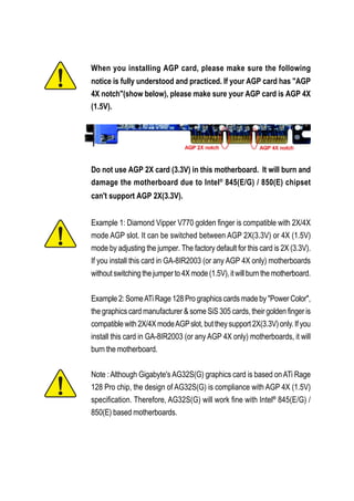
  • 1. When you installing AGP card, please make sure the following notice is fully understood and practiced. If your AGP card has "AGP 4X notch"(show below), please make sure your AGP card is AGP 4X (1.5V). Do not use AGP 2X card (3.3V) in this motherboard. It will burn and damage the motherboard due to Intel® 845(E/G) / 850(E) chipset can't support AGP 2X(3.3V). Example 1: Diamond Vipper V770 golden finger is compatible with 2X/4X mode AGP slot. It can be switched between AGP 2X(3.3V) or 4X (1.5V) mode by adjusting the jumper. The factory default for this card is 2X (3.3V). If you install this card in GA-8IR2003 (or any AGP 4X only) motherboards without switching the jumper to 4X mode (1.5V), it will burn the motherboard. Example 2: Some ATi Rage 128 Pro graphics cards made by "Power Color", the graphics card manufacturer & some SiS 305 cards, their golden finger is compatible with 2X/4X mode AGP slot, but they support 2X(3.3V) only. If you install this card in GA-8IR2003 (or any AGP 4X only) motherboards, it will burn the motherboard. Note : Although Gigabyte's AG32S(G) graphics card is based on ATi Rage 128 Pro chip, the design of AG32S(G) is compliance with AGP 4X (1.5V) specification. Therefore, AG32S(G) will work fine with Intel® 845(E/G) / 850(E) based motherboards.
  • 2. The author assumes no responsibility for any errors or omissions that may appear in this document nor does the author make a commitment to update the informa- tion contained herein. Third-party brands and names are the property of their respective owners. Please do not remove any labels on motherboard, this may void the warranty of this motherboard. Due to rapid change in technology, some of the specifications might be out of date before publication of this booklet.
  • 3. Declaration of Conformity We, Manufacturer/Importer (full address) .. G.B.T. Technology Trading GMbH Ausschlager Weg 41, 1F, 20537 Hamburg, Germany declare that the product ( description of the apparatus, system, installation to which it refers) Mother Board GA-8IR2003 is in conformity with (reference to the specification under which conformity is declared) in accordance with 89/336 EEC-EMC Directive EN 55011 Limits and methods of measurement EN 61000-3-2* Disturbances in supply systems cause of radio disturbance characteristics of EN 60555-2 by household appliances and similar industrial, scientific and medical (ISM electrical equipment “Harmonics” high frequency equipment EN 55013 Limits and methods of measurement EN 61000-3-3* Disturbances in supply systems cause of radio disturbance characteristics of by household appliances and similar EN 60555-3 broadcast receivers and associated electrical equipment “Voltage fluctuations” equipment EN 55014 Limits and methods of measurement EN 50081-1 Generic emission standard Part 1: of radio disturbance characteristics of Residual commercial and light industry household electrical appliances, portable tools and similar electrical EN 50082-1 Generic immunity standard Part 1: apparatus Residual commercial and light industry EN 55015 Limits and methods of measurement EN 55081-2 Generic emission standard Part 2: of radio disturbance characteristics of Industrial environment fluorescent lamps and luminaries EN 55020 Immunity from radio interference of EN 55082-2 Generic emission standard Part 2: broadcast receivers and associated Industrial environment equipment EN 55022 Limits and methods of measurement ENV 55104 lmmunity requirements for household of radio disturbance characteristics of appliances tools and similar apparatus information technology equipment DIN VDE 0855 Cabled distribution systems; Equipment EN50091-2 EMC requirements for uninterruptible part 10 for receiving and/or distribution from power systems (UPS) part 12 sound and television signals CE marking (EC conformity marking) The manufacturer also declares the conformity of above mentioned product with the actual required safety standards in accordance with LVD 73/23 EEC EN 60065 Safety requirements for mains operated EN 60950 Safety for information technology equipment electronic and related apparatus for including electrical bussiness equipment household and similar general use EN 60335 Safety of household and similar EN 50091-1 General and Safety requirements for electrical appliances uninterruptible power systems (UPS) Manufacturer/Importer Signature: Timmy Huang Date : May. 17, 2002 Name: Timmy Huang (Stamp)
  • 4. DECLARATION OF CONFORMITY Per FCC Part 2 Section 2.1077(a) Responsible Party Name: G.B.T. INC. (U.S.A.) Address: 17358 Railroad Street City of Industry, CA 91748 Phone/FaxNo: (818) 854-9338/ (818) 854-9339 hereby declares that the product Product Name: Motherboard ModelNumber: GA-8IR2003 Conforms to the following specifications: FCC Part 15, Subpart B, Section 15.107(a) and Section 15.109(a), Class B Digital Device Supplementary Information: This device complies with part 15 of the FCC Rules. Operation is subject to the following two conditions: (1) This device may not cause harmful and (2) this device must accept any inference received, including that may cause undesired operation. Representative Person’s Name: ERIC LU Signature: Eric Lu Date: May 17, 2 002
  • 5. GA-8IR2003 P4 Titan DDR Motherboard USER'S MANUAL Pentium® 4 Processor Motherboard Rev. 2002 12ME-8IR2003-2002
  • 6. Table of Content English Item Checklist ......................................................................................... 4 WARNING! ............................................................................................... 4 Chapter 1 Introduction ............................................................................ 5 Features Summary ...................................................................................... 5 GA-8IR2003 Motherboard Layout ............................................................... 7 Chapter 2 Hardware Installation Process ............................................... 8 Step 1: Install the Central Processing Unit (CPU)....................................... 9 9 Step 1-1: CPU Installation ................................................................................................ Step 1-2: CPU Heat Sink Installation ............................................................................ 10 Step 2: Install memory modules ................................................................ 11 Step 3: Install expansion cards ................................................................. 13 Step 4: Connect ribbon cables, cabinet wires and power supply ............ 14 Step 4-1: I/O Back Panel Introduction ........................................................................... 14 Step 4-2: Connectors Introduction ................................................................................. 16 Chapter 3 BIOS Setup ......................................................................... 27 The Main Menu (For example: BIOS Ver. : E1) ........................................ 28 Standard CMOS Features......................................................................... 30 Advanced BIOS Features .......................................................................... 33 Integrated Peripherals .............................................................................. 35 Power Management Setup ....................................................................... 39 PnP/PCI Configurations ............................................................................. 42 PC Health Status........................................................................................ 43 GA-8IR2003 Motherboard -2-
  • 7. English Frequency/Voltage Control ........................................................................ 45 Top Performance ...................................................................................... 47 Load Fail-Safe Defaults ............................................................................. 48 Load Optimized Defaults ........................................................................... 49 Set Supervisor/User Password .................................................................. 50 Save & Exit Setup ....................................................................................... 51 Exit Without Saving ................................................................................... 52 Chapter 4 Technical Reference ........................................................... 53 Block Diagram ........................................................................................... 53 @BIOS™ Introduction ................................................................................. 54 EasyTune™ 4 Introduction ......................................................................... 55 Flash BIOS Method Introduction ............................................................... 56 Method 1 : Q-Flash ......................................................................................................... 56 Method 2 : BIOS Flash Utility ........................................................................................ 58 Method 3 : @BIOS Utility ................................................................................................ 69 2- / 4- / 6-Channel Audio Function Introuction .......................................... 71 Chapter 5 Appendix ............................................................................. 77 -3- Table of Content
  • 8. Item Checklist English The GA-8IR2003 motherboard 2 Port USB Cable x 1 IDE cable x 1 / Floppy cable x 1 4 Port USB Cable x 1 CD for motherboard driver & utility SPDIF KIT x 1 (SPD-KIT) GA-8IR2003 user's manual IEEE 1394 Cable x 1 I/O Shield Audio Combo Kit x 1 Quick PC Installation Guide Motherboard Settings Label RAID Manual WARNING! Computer motherboards and expansion cards contain very delicate Integrated Circuit (IC) chips. To protect them against damage from static electricity, you should follow some precautions whenever you work on your computer. 1. Unplug your computer when working on the inside. 2. Use a grounded wrist strap before handling computer components. If you do not have one, touch both of your hands to a safely grounded object or to a metal object, such as the power supply case. 3. Hold components by the edges and try not touch the IC chips, leads or connectors, or other components. 4. Place components on a grounded antistatic pad or on the bag that came with the components whenever the components are separated from the system. 5. Ensure that the ATX power supply is switched off before you plug in or remove the ATX power connector on the motherboard. Installing the motherboard to the chassis... If the motherboard has mounting holes, but they don't line up with the holes on the base and there are no slots to attach the spacers, do not become alarmed you can still attach the spacers to the mounting holes. Just cut the bottom portion of the spacers (the spacer may be a little hard to cut off, so be careful of your hands). In this way you can still attach the motherboard to the base without worrying about short circuits. Sometimes you may need to use the plastic springs to isolate the screw from the motherboard PCB surface, because the circuit wire may be near by the hole. Be careful, don't let the screw contact any printed circuit write or parts on the PCB that are near the fixing hole, otherwise it may damage the board or cause board malfunctioning. GA-8IR2003 Motherboard -4-
  • 9. Chapter 1 Introduction English Features Summary Form Factor 19.6cm x 29.5cm ATX size form factor, 4 layers PCB CPU Socket 478 for Intel® Micro FC-PGA2 Pentium® 4 processor Support Intel® Pentium® 4 (Northwood, 0.13 m) processor Support Intel® Pentium® 4 Processor with HT Technology * Intel® Pentium® 4 400/533MHz FSB Auto detect and optimized setting for Pentium® 4 processor 2nd cache depends on CPU Chipset Chipset Intel® 845 HOST/AGP/Controller ICH2 I/O Controller Hub Memory 3 184-pin DDR DIMM sockets Supports PC2100 DDR or PC1600 DDR DIMM Supports up to 2GB DRAM (Max) Supports only 2.5V DDR DIMM Supports 64bit ECC type DRAM integrity mode I/O Control ITE8712 Slots 1 AGP slot 4X (1.5V) device support 5 PCI slot supports 33MHz & PCI 2.2 compliant On-Board IDE 2 IDE bus master (DMA33/ATA66/ATA100) IDE ports for up to 4 ATAPI devices Supports PIO mode3, 4 (UDMA 33/ATA66/ATA100) IDE & ATAPI CD-ROM On-Board Peripherals 1 Floppy port supports 2 FDD with 360K, 720K,1.2M, 1.44M and 2.88M bytes 1 Parallel port supports Normal/EPP/ECP mode 2 Serial ports (COMA & COMB) 4 x USB 1.1 (2 by cable ) 1 Front Audio connector Hardware Monitor CPU/System fan revolution detect CPU temperature detect CPU warning temperature System voltage detect CPU/System fan fail warning to be continued...... -5- Introduction
  • 10. On-Board Sound Realtek ALC650 CODEC English Line Out / 2 front speaker Line In / 2 rear speaker(by s/w switch) Mic In / center & subwoofer(by s/w switch) SPDIF In / Out CD In / AUX In / Game port PS/2 Connector PS/2 Keyboard interface and PS/2 Mouse interface BIOS Licensed AWARD BIOS, 2M bit FWH Supports Q-Flash Additional Features PS/2 Keyboard password power on PS/2 Mouse power on STR(Suspend-To-RAM) AC Recovery USB KB/Mouse wake up from S3 Poly fuse for keyboard, USB, game port over-current protection Supports @BIOS Supports EasyTune 4 Jumper less Over Clock (CPU/DDR/AGP) by BIOS Overclocking "*" HT functionality requirement content : Enabling the functionality of Hyper-Threading Technology for your computer system requires all of the following platform components: - CPU: An Intel® Pentium 4 Processor with HT Technology - Chipset: An Intel® Chipset that supports HT Technology - BIOS: A BIOS that supports HT Technology and has it enabled - OS: An operation system that has optimizations for HT Technology Please set the CPU host frequency in accordance with your processor's specifications. We don't recommend you to set the system bus frequency over the CPU's specification because these specific bus frequencies are not the standard specifications for CPU, chipset and most of the peripherals. Whether your system can run under these specific bus frequencies properly will depend on your hardware configurations, including CPU, Chipsets, SDRAM, Cards…etc. GA-8IR2003 Motherboard -6-
  • 11. GA-8IR2003 Motherboard Layout English KB_MS USB ATX COMA LPT SOCKET478 COMB FDD GA-8IR2003 F_AUDIO ATX_12V LINE_OUT LINE_IN GAME CPU_FAN MIC_IN Intel 845 AGP DDR2 DDR3 DDR1 CD_IN CODEC 2X_DET BATTERY PCI1 PCI2 SYS _FAN SUR_CEN PCI3 ICH2 CLR_PWD CI P4 Titan PCI4 IDE2 PCI5 ITE8712 IDE1 PWR_LED AUX_IN SPDIF_IO BIOS F_USB1 F_PANEL -7- Hardware Installation Process
  • 12. Chapter 2 Hardware Installation Process English To set up your computer, you must complete the following steps: Step 1- Install the Central Processing Unit (CPU) Step 2- Install memory modules Step 3- Install expansion cards Step 4- Connect ribbon cables, cabinet wires, and power supply Step 5- Setup BIOS software Step 6- Install supporting software tools Step 4 Step 1 Step 2 Step 4 Step 4 Step 1 Step 3 Step 4 GA-8IR2003 Motherboard -8-
  • 13. Step 1: Install the Central Processing Unit (CPU) English Step 1-1: CPU Installation Socket Angling the Actuation rod to 650 Lever 1. Angling the rod to 65-degree maybe feel a 2. Pull the rod to the 90-degree directly . kind of tight , and then continue pull the rod to 90-degree when a noise "cough" made. Pin1 indicator Pin1 indicator 3. CPU Top View 4. Locate Pin 1 in the socket and look for a (golden) cut edge on the CPU upper corner. Then insert the CPU into the socket. Please make sure the CPU type is supported by the motherboard. If you do not match the CPU socket Pin 1 and CPU cut edge well, it will cause improper installation. Please change the insert orientation. -9- Hardware Installation Process
  • 14. Step 1-2: CPU Heat Sink Installation English 1. Hook one end of the cooler bracket 2. Hook the other end of the cooler to the CPU socket first. bracket to the CPU socket. Please use Intel approved cooling fan. We recommend you to apply the thermal tape to provide better heat conduction between your CPU and heatsink. (The CPU cooling fan might stick to the CPU due to the hardening of the thermal paste. During this condition if you try to remove the cooling fan, you might pull the processor out of the CPU socket alone with the cooling fan, and might damage the processor. To avoid this from happening, we suggest you to either use thermal tape instead of thermal paste, or remove the cooling fan with extreme caution.) Make sure the CPU fan power cable is plugged in to the CPU fan connector, this completes the installation. Please refer to CPU heat sink user's manual for more detail installation procedure. GA-8IR2003 Motherboard - 10 -
  • 15. Step 2: Install memory modules English The motherboard has 3 dual inline memory module (DIMM) sockets, but it can only support a maximum of 4 banks of DDR memory. DDR slot 1 uses 2 banks, DDR slot 2 & 3 share the remaining 2 banks. Please refer to the following tables for possible memory configurations supported. The BIOS will automatically detects memory type and size. To install the memory module, just push it vertically into the DIMM socket. The DIMM module can only fit in one direction due to the notch. Memory size can vary between sockets. Total Memory Sizes With Unbuffered DDR DIMM Devices used on DIMM 1 DIMM x 64 / x 72 2 DIMMs x 64 / x 72 3 DIMMs x 64 / x 72 64 Mbit (2Mx8x4 banks) 128 MBytes 256 MBytes 256 MBytes 64 Mbit (1Mx16x4 banks) 32 MBytes 64 MBytes 96 MBytes 128 Mbit(4Mx8x4 banks) 256 MBytes 512 MBytes 512 MBytes 128 Mbit(2Mx16x4 banks) 64 MBytes 128 MBytes 192 MBytes 256 Mbit(8Mx8x4 banks) 512 MBytes 1 GBytes 1 GBytes 256 Mbit(4Mx16x4 banks) 128 MBytes 256 MBytes 384 MBytes 512 Mbit(16Mx8x4 banks) 1 GBytes 2 GBytes 2 GBytes 512 Mbit(8Mx16x4 banks) 256 MBytes 512 MBytes 768 MBytes DDR1 DDR2 DDR3 S S S D S S D D X D X D S D X S X D D: Double Sided DIMM S:Single Sided DIMM X: Not Use - 11 - Hardware Installation Process
  • 16. English DDR 1. The DIMM socket has a notch, so the DIMM memory module can only fit in one direction. 2. Insert the DIMM memory module vertically into the DIMM socket. Then push it down. 3. Close the plastic clip at both edges of the DIMM sockets to lock the DIMM module. Reverse the installation steps when you wish to remove the DIMM module. DDR Introduction Established on the existing SDRAM industry infrastructure, DDR (Double Data Rate) memory is a high performance and cost-effective solution that allows easy adoption for memory vendors, OEMs and system integrators. DDR memory is a sensible evolutionary solution for the PC industry that builds on the existing SDRAM infrastructure, yet makes awesome advances in solving the system performance bottleneck by doubling the memory bandwidth. DDR SDRAM will offer a superior solution and migration path from existing SDRAM designs due to its availability, pricing and overall market support. PC2100 DDR memory (DDR266) doubles the data rate through reading and writing at both the rising and falling edge of the clock, achieving data bandwidth 2X greater than PC133 when running with the same DRAM clock frequency. With peak bandwidth of 2.664GB per second, DDR memory enables system OEMs to build high performance and low latency DRAM subsystems that are suitable for servers, workstations, high- end PC's and value desktop SMA systems. With a core voltage of only 2.5 Volts compared to conventional SDRAM's 3.3 volts, DDR memory is a compelling solution for small form factor desktops and notebook applications. Please note that the DIMM module can only fit in one direction due to the one notch. Wrong orientation will cause improper installation. Please change the insert orientation. GA-8IR2003 Motherboard - 12 -
  • 17. Step 3: Install expansion cards English 1. Read the related expansion card's instruction document before install the expansion card into the computer. 2. Remove your computer's chassis cover, screws and slot bracket from the computer. 3. Press the expansion card firmly into expansion slot in motherboard. 4. Be sure the metal contacts on the card are indeed seated in the slot. 5. Replace the screw to secure the slot bracket of the expansion card. 6. Replace your computer's chassis cover. 7. Power on the computer, if necessary, setup BIOS utility of expansion card from BIOS. 8. Install related driver from the operating system. Please carefully pull out the small white-drawable bar at the end of the AGP slot when you try to install / uninstall the AGP card. Please align the AGP Card AGP card to the onboard AGP slot and press firmly down on the slot. Make sure your AGP card is locked by the small white-drawable bar. When an AGP 2X (3.3V) card is installed the 2X_DET will light up, indicating a non-supported graphics card is inserted. Informing users that system might not boot up normally due to AGP 2X (3.3V) is not supported by the chipset. - 13 - Hardware Installation Process
  • 18. Step 4: Connect ribbon cables, cabinet wires and English power supply Step 4-1: I/O Back Panel Introduction PS/2 Keyboard and PS/2 Mouse Connector This connector supports standard PS/2 PS/2 Mouse Connector keyboard and PS/2 mouse. (6 pin Female) PS/2 Keyboard Connector (6 pin Female) USB Connector Before you connect your device(s) into USB connector(s), please make sure your device(s) such as USB keyboard,mouse, scanner, zip, USB 0 speaker...etc. Have a standard USB interface. USB 1 Also make sure your OS supports USB controller. If your OS does not support USB controller, please contact OS vendor for possible patch or driver upgrade. For more information please contact your OS or device(s) vendors. GA-8IR2003 Motherboard - 14 -
  • 19. Parallel Port and Serial Ports (COMA / COMB) English Parallel Port This connector supports 2 standard COM ports (25 pin Female) and 1 Parallel port. Device like printer can be connected to Parallel port; mouse and modem etc. can be connected to Serial ports. COMA COMB Serial Port (9 pin Male) Game / MIDI Ports This connector supports joystick, MIDI keyboard and other relate audio devices. Joystick/ MIDI (15 pin Female) Audio Connectors After install onboard audio driver, you may con- nect speaker to Line Out jack, microphone to MIC In jack. Device like CD-ROM,walkman etc. can be connected to Line-In jack. Please note: You are able to use 2-/4-/6-channel audio feature by S/W selection. Line Out If you want to enable 6-channel function, you MIC In (Front Speaker) (Center and have 2 choose for hardware connection. Subwoofer) Method1: Connect "Front Speaker" to "Line Out" Line In Connect "Rear Speaker" to "Line In" (Rear Speaker) Connect "Center and Subwoofer" to "MIC Out ". Method2: You can refer to page 22, and contact your nearest dealer for optional SUR_CEN cable. If you want the detail information for 2-/4-/6-channel audio setup installation, please refer to page 71. - 15 - Hardware Installation Process
  • 20. Step 4-2: Connectors Introduction English 2 1 10 5 3 9 12 18 11 4 17 16 6 8 13 14 15 7 1) ATX_12V 10) F_AUDIO 2) ATX 11) SUR_CEN 3) CPU_FAN 12) CD_IN 4) SYS_FAN 13) AUX_IN 5) FDD 14) SPDIF_IO 6) IDE1 / IDE2 15) F_USB1 7) F_PANEL 16) CI 8) PWR_LED 17) CLR_PWD 9) 2X_DET 18) BATTERY GA-8IR2003 Motherboard - 16 -
  • 21. 1) ATX_12V (+12V Power Connector) English This connector (ATX_12V) supplies the CPU operation voltage (Vcore). If this "ATX_12V connector" is not connected, system cannot boot. Pin No. Definition 2 1 1 GND 2 GND 4 3 3 +12V 4 +12V 2) ATX (ATX Power) AC power cord should only be connected to your power supply unit after ATX power cable and other related devices are firmly connected to the mainboard. Pin No. Definition 1 3.3V 2 3.3V 3 GND 4 VCC 10 20 5 GND 6 VCC 7 GND 8 Power Good 9 5V SB (stand by +5V) 10 +12V 11 3.3V 12 -12V 13 GND 14 PS_ON(soft on/off) 1 11 15 GND 16 GND 17 GND 18 -5V 19 VCC 20 VCC - 17 - Hardware Installation Process
  • 22. 3) CPU_FAN (CPU Fan Connector) English Please note, a proper installation of the CPU cooler is essential to prevent the CPU from running under abnormal condition or damaged by overheating. The CPU fan connector supports Max. current up to 600 mA. Pin No. Definition 1 GND 2 +12V 1 3 Sense 4) SYS_FAN (System Fan Connector) This connector allows you to link with the cooling fan on the system case to lower the system temperature. 1 Pin No. Definition 1 GND 2 +12V 3 Sense GA-8IR2003 Motherboard - 18 -
  • 23. 5) FDD (Floppy Connector) English Please connect the floppy drive ribbon cables to FDD. It supports 360K, 1.2M, 720K, 1.44M and 2.88M bytes floppy disk types. The red stripe of the ribbon cable must be the same side with the Pin1. 34 33 2 1 6) IDE1 / IDE2 (IDE1 / IDE2 Connector) Important Notice: Please connect first hard disk to IDE1 and connect CD-ROM to IDE2. The red stripe of the ribbon cable must be the same side with the Pin1. 39 1 IDE2 IDE1 40 2 - 19 - Hardware Installation Process
  • 24. 7) F_PANEL (2 x 10 pins Connector) English Please connect the power LED, PC speaker, reset switch and power switch etc of your chassisfront panel to the F_PANEL connector according to the pin assignment above. Speaker Connector Message LED/ Power/ Soft Power Sleep LED Connector MSG+ PW+ SPEAK+ SPEAK- MSG- PW- 1 1 1 19 20 1 2 1 1 HD- RES- NC RES+ HD+ Reset Switch IDE Hard Disk Active LED HD (IDE Hard Disk Active LED) Pin 1: LED anode(+) (Blue) Pin 2: LED cathode(-) SPK (Speaker Connector) Pin 1: VCC(+) (Amber) Pin 2- Pin 3: NC Pin 4: Data(-) RES (Reset Switch) Open: Normal Operation (Green) Close: Reset Hardware System PW (Soft Power Connector) Open: Normal Operation (Red) Close: Power On/Off MSG(Message LED/ Power/ Sleep LED) Pin 1: LED anode(+) (Yellow) Pin 2: LED cathode(-) NC (Purple) NC GA-8IR2003 Motherboard - 20 -
  • 25. 8) PWR_LED English PWR_LED is connect with the system power indicator to indicate whether the system is on/off. It will blink when the system enters suspend mode. If you use dual color LED, power LED will turn to another color. 1 Pin No. Definition 1 MPD+ 2 MPD- 3 MPD- 9) 2X_DET When an AGP 2X (3.3V) card is installed the AGP_LED will light up, indicating a non-supported graphics card is inserted. Informing users that system might not boot up normally due to AGP 2X (3.3V) is not supported by the chipset. + _ - 21 - Hardware Installation Process
  • 26. 10) F_AUDIO (Front Audio Connector) English If you want to use Front Audio connector, you must remove 5-6, 9-10 Jumper. In order to utilize the front audio header, your chassis must have front audio connector. Also please make sure the pin assigment on the cable is the same as the pin assigment on the MB header. To find out if the chassis you are buying support front audio connector, please contact your dealer. Please note, you can have the of using front audio connector or of using rear audio connector to play sound. Pin No. Definition 1 MIC 2 GND 1 2 3 REF 4 Power 5 Front Audio (R) 6 Rear Audio (R) 9 10 7 Reserved 8 No Pin 9 Front Audio (L) 10 Rear Audio (L) 11) SUR_CEN (Surround Center Connector) Please contact your nearest dealer for optional SUR_CEN cable. Pin No. Definition 1 SUR OUTL 2 SUR OUTR 2 6 3 GND 1 5 4 No Pin 5 CENTER_OUT 6 BASS_OUT GA-8IR2003 Motherboard - 22 -
  • 27. 12) CD_IN (CD In Connector) English Connect CD-ROM or DVD-ROM audio out to the connector. 1 Pin No. Definition 1 AUX-L 2 GND 3 GND 4 AUX-R 13) AUX_IN (AUX In Connector) Connect other device (such as PCI TV Tunner audio out) to the connector. Pin No. Definition 1 AUX-L 2 GND 1 3 GND 4 AUX-R - 23 - Hardware Installation Process
  • 28. 14) SPDIF_IO (SPDIF In / Out) English The SPDIF output is capable of providing digital audio to external speakers or compressed AC3 data to an external Dolby Digital Decoder. Use this feature only when your stereo system has digital input function. Use SPDIF IN feature only when your device has digital output function. Pin No. Definition 1 VCC 5 1 2 No Pin 3 SPDIF 4 SPDIFI 6 2 5 GND 6 GND 15) F_USB1 (Front USB Connector, Yellow) Be careful with the polarity of the front USB connector. Check the pin assignment while you connect the front USB cable. Please contact your nearest dealer for optional front USB cable. Pin No. Definition 1 Power 2 Power 3 USB Dx- 2 10 4 USB Dy- 5 USB Dx+ F_USB1 6 USB Dy+ 1 9 7 GND 8 GND 9 No Pin 10 NC GA-8IR2003 Motherboard - 24 -
  • 29. 16) CI (CASE OPEN) English This 2-pin connector allows your system to enable or disable the "Case Open" item in BIOS, if the system case begin remove. Pin No. Definition 1 Signal 1 2 GND 17) CLR_PWD When Jumper is set to "open" and system is restarted, the password that is set will be cleared. On the contrary when Jumper is set to "close", the current status remains. 1 Open: Clear Password 1 Close: Normal - 25 - Hardware Installation Process
  • 30. 18) BATTERY English + CAUTION Danger of explosion if battery is incorrectly replaced. Replace only with the same or equivalent type recommended by the manufacturer. Dispose of used batteries according to the manufacturer's instructions. If you want to erase CMOS... 1. Turn OFF the computer and unplug the power cord. 2. Remove the battery, wait for 30 second. 3. Re-install the battery. 4. Plug the power cord and turn ON the computer. GA-8IR2003 Motherboard - 26 -
  • 31. Chapter 3 BIOS Setup English BIOS Setup is an overview of the BIOS Setup Program. The program that allows users to modify the basic system configuration. This type of information is stored in battery-backed CMOS RAM so that it retains the Setup information when the power is turned off. ENTERING SETUP Powering ON the computer and pressing <Del> immediately will allow you to enter Setup. If you require more advanced BIOS settings, please go to "Advanced BIOS" setting menu. To enter Advanced BIOS setting menu, press "Ctrl+F1" key on the BIOS screen. CONTROL KEYS < > Move to previous item < > Move to next item < > Move to the item in the left hand < > Move to the item in the right hand <Enter> Select Item <Esc> Main Menu - Quit and not save changes into CMOS Status Page Setup Menu and Option Page Setup Menu - Exit current page and return to Main Menu <+/PgUp> Increase the numeric value or make changes <-/PgDn> Decrease the numeric value or make changes <F1> General help, only for Status Page Setup Menu and Option Page Setup Menu <F2> Item Help <F3> Reserved <F4> Reserved <F5> Restore the previous CMOS value from CMOS, only for Option Page Setup Menu <F6> Load the file-safe default CMOS value from BIOS default table <F7> Load the Optimized Defaults <F8> Q-Flash utility <F9> System Information <F10> Save all the CMOS changes, only for Main Menu - 27 - BIOS Setup
  • 32. GETTING HELP English Main Menu The on-line description of the highlighted setup function is displayed at the bottom of the screen. Status Page Setup Menu / Option Page Setup Menu Press F1 to pop up a small help window that describes the appropriate keys to use and the possible selections for the highlighted item. To exit the Help Window press <Esc>. The Main Menu (For example: BIOS Ver. : E1) Once you enter Award BIOS CMOS Setup Utility, the Main Menu (Figure 1) will appear on the screen. The Main Menu allows you to select from eight setup functions and two exit choices. Use arrow keys to select among the items and press <Enter> to accept or enter the sub-menu. CMOS Setup Utility-Copyright (C) 1984-2003 Award Software Standard CMOS Features Top Performance Advanced BIOS Features Load Fail-Safe Defaults Integrated Peripherals Load Optimized Defaults Power Management Setup Set Supervisor Password PnP/PCI Configurations Set User Password PC Health Status Save & Exit Setup Frequency/Voltage Control Exit Without Saving ESC: Quit : Select Item F8: Q-Flash F10: Save & Exit Setup Time, Date, Hard Disk Type... Figure 1: Main Menu If you can't find the setting you want, please press "Ctrl+F1" to search the advanced option widden. Standard CMOS Features This setup page includes all the items in standard compatible BIOS. Advanced BIOS Features This setup page includes all the items of Award special enhanced features. GA-8IR2003 Motherboard - 28 -
  • 33. Integrated Peripherals English This setup page includes all onboard peripherals. Power Management Setup This setup page includes all the items of Green function features. PnP/PCI Configurations This setup page includes all the configurations of PCI & PnP ISA resources. PC Health Status This setup page is the System auto detect Temperature, voltage, fan, speed. Frequency/Voltage Control This setup page is control CPU’s clock and frequency ratio. Top Performance If you wish to maximize the performance of your system, set "Top Performance" as "Enabled". Load Fail-Safe Defaults Fail-Safe Defaults indicates the value of the system parameters which the system would be in safe configuration. Load Optimized Defaults Optimized Defaults indicates the value of the system parameters which the system would be in best performance configuration. Set Supervisor password Change, set, or disable password. It allows you to limit access to the system and Setup, or just to Setup. Set User password Change, set, or disable password. It allows you to limit access to the system. Save & Exit Setup Save CMOS value settings to CMOS and exit setup. Exit Without Saving Abandon all CMOS value changes and exit setup. - 29 - BIOS Setup
  • 34. Standard CMOS Features English CMOS Setup Utility-Copyright (C) 1984-2003 Award Software Standard CMOS Features Date (mm:dd:yy) Thu, Jan 9 2003 Item Help Time (hh:mm:ss) 22:31:24 Menu Level Change the day, month, IDE Primary Master [None] year IDE Primary Slave [None] IDE Secondary Master [None] <Week> IDE Secondary Slave [None] Sun. to Sat. Drive A [1.44M, 3.5"] <Month> Drive B [None] Jan. to Dec. Floppy 3 Mode Support [Disabled] <Day> Halt On [All, But Keyboard] 1 to 31 (or maximum allowed in the month) Base Memory 640K Extended Memory 130048K <Year> Total Memory 131072K 1999 to 2098 : Move Enter:Select +/-/PU/PD:Value F10:Save ESC:Exit F1:General Help F5:Previous Values F6:Fail-Safe Defaults F7:Optimized Defaults Figure 2: Standard CMOS Features Date The date format is <week>, <month>, <day>, <year>. Week The week, from Sun to Sat, determined by the BIOS and is display only Month The month, Jan. Through Dec. Day The day, from 1 to 31 (or the maximum allowed in the month) Year The year, from 1999 through 2098 GA-8IR2003 Motherboard - 30 -
  • 35. Time English The times format in <hour> <minute> <second>. The time is calculated base on the 24-hour military- time clock. For example, 1 p.m. is 13:00:00. IDE Primary Master, Slave / IDE Secondary Master, Slave The category identifies the types of hard disk from drive C to F that has been installed in the computer. There are two types: auto type, and manual type. Manual type is user-definable; Auto type which will automatically detect HDD type. Note that the specifications of your drive must match with the drive table. The hard disk will not work properly if you enter improper information for this category. If you select User Type, related information will be asked to enter to the following items. Enter the information directly from the keyboard and press <Enter>. Such information should be provided in the documentation form your hard disk vendor or the system manufacturer. CYLS. Number of cylinders HEADS Number of heads PRECOMP Write precomp LANDZONE Landing zone SECTORSNumber of sectors If a hard disk has not been installed select NONE and press <Enter>. Drive A / Drive B The category identifies the types of floppy disk drive A or drive B that has been installed in the computer. None No floppy drive installed 360K, 5.25 in. 5.25 inch PC-type standard drive; 360K byte capacity. 1.2M, 5.25 in. 5.25 inch AT-type high-density drive; 1.2M byte capacity (3.5 inch when 3 Mode is Enabled). 720K, 3.5 in. 3.5 inch double-sided drive; 720K byte capacity 1.44M, 3.5 in. 3.5 inch double-sided drive; 1.44M byte capacity. 2.88M, 3.5 in. 3.5 inch double-sided drive; 2.88M byte capacity. - 31 - BIOS Setup
  • 36. Floppy 3 Mode Support (for Japan Area) English Disabled Normal Floppy Drive. (Default value) Drive A Drive A is 3 mode Floppy Drive. Drive B Drive B is 3 mode Floppy Drive. Both Drive A & B are 3 mode Floppy Drives. Halt on The category determines whether the computer will stop if an error is detected during power up. NO Errors The system boot will not stop for any error that may be detected and you will be prompted. All Errors Whenever the BIOS detects a non-fatal error the system will be stopped. All, But Keyboard The system boot will not stop for a keyboard error; it will stop for all other errors. (Default value) All, But Diskette The system boot will not stop for a disk error; it will stop for all other errors. All, But Disk/Key The system boot will not stop for a keyboard or disk error; it will stop for all other errors. Memory The category is display-only which is determined by POST (Power On Self Test) of the BIOS. Base Memory The POST of the BIOS will determine the amount of base (or conventional) memory installed in the system. The value of the base memory is typically 512 K for systems with 512 K memory installed on the motherboard, or 640 K for systems with 640 K or more memory installed on the motherboard. ExtendedMemory The BIOS determines how much extended memory is present during the POST. This is the amount of memory located above 1 MB in the CPU's memory address map. GA-8IR2003 Motherboard - 32 -
  • 37. Advanced BIOS Features English CMOS Setup Utility-Copyright (C) 1984-2003 Award Software Advanced BIOS Features First Boot Device [Floppy] Item Help Second Boot Device [HDD-0] Menu Level Third Boot Device [CDROM] Select Boot Device Boot Up Floppy Seek [Disabled] priority Password Check [Setup] CPU Hyper-Threading # [Enabled] [Floppy] DRAM Data Integrity Mode [Non-ECC] Boot from floppy Init Display First [AGP] [LS120] Boot from LS120 [HDD-0] Boot from First HDD [HDD-1] Boot from second HDD : Move Enter:Select +/-/PU/PD:Value F10:Save ESC:Exit F1:General Help F5:Previous Values F6:Fail-Safe Defaults F7:Optimized Defaults Figure 3: Advanced BIOS Features " # " System will detect automatically and show up when you install the Intel® Pentium® 4 processor with HT Technology. First / Second / Third Boot Device Floppy Select your boot device priority by Floppy. LS120 Select your boot device priority by LS120. HDD-0~3 Select your boot device priority by HDD-0~3. SCSI Select your boot device priority by SCSI. CDROM Select your boot device priority by CDROM. ZIP Select your boot device priority by ZIP. USB-FDD Select your boot device priority by USB-FDD. USB-ZIP Select your boot device priority by USB-ZIP. - 33 - BIOS Setup
  • 38. USB-CDROM Select your boot device priority by USB-CDROM. English USB-HDD Select your boot device priority by USB-HDD. LAN Select your boot device priority by LAN. Disabled Select your boot device priority by Disabled. Boot Up Floppy Seek During POST, BIOS will determine the floppy disk drive installed is 40 or 80 tracks. 360K type is 40 tracks 720K, 1.2M and 1.44M are all 80 tracks. Enabled BIOS searches for floppy disk drive to determine it is 40 or 80 tracks. Note that BIOS can not tell from 720K, 1.2M or 1.44M drive type as they are all 80tracks. Disabled BIOS will not search for the type of floppy disk drive by track number. Note that there will not be any warning message if the drive installed is 360K. (Default value) Password Check System The system can not boot and can not access to Setup page will be denied if the correct password is not entered at the prompt. Setup The system will boot, but access to Setup will be denied if the correct password is not entered at the prompt. (Default value) CPU Hyper-Threading # Disabled Disable CPU Hyper Threading. Enabled Enable CPU Hyper Threading Feature. Please note that this feature is only working for operating system with multi processors mode supported. (Default value) DRAM Data Integrity Mode If you are using the Non-ECC DRAM, the mode will show "Non-ECC" and this function is disabled. ECC Set DRAM Data Integrity Mode by ECC. Non-ECC Set DRAM Data Integrity Mode by Non-ECC. (Default value) Init Display First AGP Set Init Display First to AGP. (Default value) PCI Set Init Display First to PCI. GA-8IR2003 Motherboard - 34 -
  • 39. Integrated Peripherals English CMOS Setup Utility-Copyright (C) 1984-2003 Award Software Integrated Peripherals On-Chip Primary PCI IDE [Enabled] Item Help On-Chip Secondary PCI IDE [Enabled] Menu Level IDE1 Conductor Cable [Auto] [Auto] IDE2 Conductor Cable [Auto] Auto-detect IDE USB Controller [Enabled] cable type USB Keyboard Support [Disabled] USB Mouse Support [Disabled] [ATA66/100/133] AC97 Audio [Auto] Set Conductor cable Onboard Serial Port 1 [3F8/IRQ4] to ATA66/100/133(80 Onboard Serial Port 2 [2F8/IRQ3] -pins) Onboard Parallel Port [378/IRQ7] Parallel Port Mode [SPP] [ATA33] x ECP Mode Use DMA 3 Set Conductor cable Game Port Address [201] to ATA33(40-pins) Midi Port Address [330] Midi Port IRQ [10] : Move Enter:Select +/-/PU/PD:Value F10:Save ESC:Exit F1:General Help F5:Previous Values F6:Fail-Safe Defaults F7:Optimized Defaults Figure 4: Integrated Peripherals On-Chip Primary PCI IDE Enabled Enable onboard 1st channel IDE port. (Default value) Disabled Disable onboard 1st channel IDE port. On-Chip Secondary PCI IDE Enabled Enable onboard 2nd channel IDE port. (Default value) Disabled Disable onboard 2nd channel IDE port. - 35 - BIOS Setup
  • 40. IDE1 Conductor Cable English Auto Will be automatically detected by BIOS. (Default Value) ATA66/100 Set IDE1 Conductor Cable to ATA66/100 (Please make sure your IDE device and cable is compatible with ATA66/100). ATA33 Set IDE1 Conductor Cable to ATA33 (Please make sure your IDE device and cable is compatible with ATA33). IDE2 Conductor Cable Auto Will be automatically detected by BIOS. (Default Value) ATA66/100 Set IDE2 Conductor Cable to ATA66/100 (Please make sure your IDE device and cable is compatible with ATA66/100). ATA33 Set IDE2 Conductor Cable to ATA33 (Please make sure your IDE device and cable is compatible with ATA33). USB Controller Enabled Enable USB Controller. (Default value) Disabled Disable USB Controller. USB Keyboard Support Enabled Enable USB Keyboard Support. Disabled Disable USB Keyboard Support. (Default value) USB Mouse Support Enabled Enable USB Mouse Support. Disabled Disable USB Mouse Support. (Default value) AC97 Audio Auto Enable onboard AC'97 audio function. (Default Value) Disabled Disable this function. GA-8IR2003 Motherboard - 36 -
  • 41. Onboard Serial Port 1 English Auto BIOS will automatically setup the port 1 address. 3F8/IRQ4 Enable onboard Serial port 1 and address is 3F8. (Default value) 2F8/IRQ3 Enable onboard Serial port 1 and address is 2F8. 3E8/IRQ4 Enable onboard Serial port 1 and address is 3E8. 2E8/IRQ3 Enable onboard Serial port 1 and address is 2E8. Disabled Disable onboard Serial port 1. Onboard Serial Port 2 Auto BIOS will automatically setup the port 2 address. 3F8/IRQ4 Enable onboard Serial port 2 and address is 3F8. 2F8/IRQ3 Enable onboard Serial port 2 and address is 2F8. (Default value) 3E8/IRQ4 Enable onboard Serial port 2 and address is 3E8. 2E8/IRQ3 Enable onboard Serial port 2 and address is 2E8. Disabled Disable onboard Serial port 2. Onboard Parallel port 378/IRQ7 Enable onboard LPT port and address is 378/IRQ7. (Default Value) 278/IRQ5 Enable onboard LPT port and address is 278/IRQ5. Disabled Disable onboard LPT port. 3BC/IRQ7 Enable onboard LPT port and address is 3BC/IRQ7. Parallel Port Mode SPP Using Parallel port as Standard Parallel Port. (Default Value) EPP Using Parallel port as Enhanced Parallel Port. ECP Using Parallel port as Extended Capabilities Port. ECP+EPP Using Parallel port as ECP & EPP mode. ECP Mode Use DMA 3 Set ECP Mode Use DMA to 3. (Default Value) 1 Set ECP Mode Use DMA to 1. - 37 - BIOS Setup
  • 42. Game Port Address English 201 Set Game Port Address to 201. (Default Value) 209 Set Game Port Address to 209. Disabled Disable this function. Midi Port Address 290 Set Midi Port Address to 290. 300 Set Midi Port Address to 300. 330 Set Midi Port Address to 330.(Default Value) Disabled Disable this function. Midi Port IRQ 5 Set Midi Port IRQ to 5. 10 Set Midi Port IRQ to 10. (Default Value) GA-8IR2003 Motherboard - 38 -
  • 43. Power Management Setup English CMOS Setup Utility-Copyright (C) 1984-2003 Award Software Power Management Setup ACPI Suspend Type [S1(POS)] Item Help Power LED in S1 state [Blinking] Menu Level Soft-Off by PWR-BTTN [Instant-Off] [S1] PME Event Wake Up [Enabled] Set suspend type to ModemRingOn [Enabled] Power On Suspend under Resume by Alarm [Disabled] ACPI OS x Date (of Month) Alarm 0 x Time (hh:mm:ss) Alarm 0:0:0 [S3] Power On by Mouse [Disabled] Set suspend type to Power On by Keyboard [Disabled] Suspend to RAM under x KB Power ON Password Enter ACPI OS AC Back Function [Soft-Off] : Move Enter:Select +/-/PU/PD:Value F10:Save ESC:Exit F1:General Help F5:Previous Values F6:Fail-Safe Defaults F7:Optimized Defaults Figure 5: Power Management Setup ACPI Suspend Type S1(POS) Set ACPI suspend type to S1. (Default Value) S3(STR) Set ACPI suspend type to S3. Power LED in S1 state Blinking In standby mode(S1), power LED will blink. (Default Value) Dual/Off In standby mode(S1): a. If use single color LED, power LED will turn off. b. If use dual color LED, power LED will turn to another color. - 39 - BIOS Setup
  • 44. Soft-off by PWR_BTTN English Instant-off Press power button then Power off instantly. (Default value) Delay 4 Sec. Press power button 4 sec to Power off. Enter suspend if button is pressed less than 4 sec. PME Event Wake Up Disabled Disable this function. Enabled Enable PME Event Wake up. (Default Value) ModemRingOn Disabled Disable Modem Ring On / Wake On LAN function. Enabled The modem ring / LAN wake up will bring the system out of soft-off or suspend state if this option is set "Enabled". (Default Value) Resume by Alarm You can set "Resume by Alarm" item to enabled and key in Data/time to power on system. Disabled Disable this function. (Default Value) Enabled Enable alarm function to POWER ON system. If RTC Alarm Lead To Power On is Enabled. Date ( of Month) Alarm : Everyday, 1~31 Time ( hh: mm: ss) Alarm : (0~23) : (0~59) : (0~59) Power On By Mouse Disabled Disabled this function. (Default value) Mouse Click Set mouse power on by double click mouse bottom. Power On By Keyboard Password Enter from 1 to 5 characters to set the Keyboard Power On Password. Disabled Disabled this function. (Default value) Keyboard 98 If your keyboard have "POWER Key" button, you can press the key to power on your system. GA-8IR2003 Motherboard - 40 -
  • 45. KB Power ON Password English Enter Input password (from 1 to 5 characters) and press Enter to set the Key board Power On Password. AC Back Function Memory System power on depends on the status before AC lost. Soft-Off Always in Off state when AC back. (Default value) Full-On Always power on the system when AC back. - 41 - BIOS Setup
  • 46. PnP/PCI Configurations English CMOS Setup Utility-Copyright (C) 1984-2003 Award Software PnP/PCI Configurations PCI 1/5 IRQ Assignment [Auto] Item Help PCI 2 IRQ Assignment [Auto] Menu Level PCI 3 IRQ Assignment [Auto] PCI 4 IRQ Assignment [Auto] Device(s) using this INT: Display Cntrlr -BUS 1 Dev 0 Func 0 : Move Enter:Select +/-/PU/PD:Value F10:Save ESC:Exit F1:General Help F5:Previous Values F6:Fail-Safe Defaults F7:Optimized Defaults Figure 6: PnP/PCI Configurations PCI 1/5 IRQ Assignment Auto Auto assign IRQ to PCI 1/5. (Default value) 3,4,5,7,9,10,11,12,14,15 Set IRQ 3,4,5,7,9,10,11,12,14,15 to PCI 1/5. PCI 2 IRQ Assignment Auto Auto assign IRQ to PCI 2. (Default value) 3,4,5,7,9,10,11,12,14,15 Set IRQ 3,4,5,7,9,10,11,12,14,15 to PCI 2. PCI 3 IRQ Assignment Auto Auto assign IRQ to PCI 3. (Default value) 3,4,5,7,9,10,11,12,14,15 Set IRQ 3,4,5,7,9,10,11,12,14,15 to PCI 3. PCI 4 IRQ Assignment Auto Auto assign IRQ to PCI 4. (Default value) 3,4,5,7,9,10,11,12,14,15 Set IRQ 3,4,5,7,9,10,11,12,14,15 to PCI 4. GA-8IR2003 Motherboard - 42 -
  • 47. PC Health Status English CMOS Setup Utility-Copyright (C) 1984-2003 Award Software PC Health Status Reset Case Open Status [Disabled] Item Help Case Opened Yes Menu Level VCORE 1.696V [Disabled] VCC18 1.776V Don't reset case +3.3V 3.248V open status +5V 5.134V +12V 12.288V [Enabled] Current CPU Temperature 33°C Clear case open Current CPU FAN Speed 4440 RPM status at next boot Current SYSTEM FAN Speed 0 RPM CPU Warning Temperature [Disabled] CPU FAN Fail Warning [Disabled] SYSTEM FAN Fail Warning [Disabled] : Move Enter:Select +/-/PU/PD:Value F10:Save ESC:Exit F1:General Help F5:Previous Values F6:Fail-Safe Defaults F7:Optimized Defaults Figure 7: PC Health Status Reset Case Open Status Case Opened If the case is closed, "Case Opened" will show "No". If the case have been opened, "Case Opened" will show "Yes". If you want to reset "Case Opened" value, set "Reset Case Open Status" to "Enabled" and save CMOS, your computer will restart. Current Voltage (V) VCORE / VCC18 / +3.3V / +5V / +12V Detect system's voltage status automatically. Current CPU Temperature Detect System/CPU temperature automatically. - 43 - BIOS Setup
  • 48. Current CPU/SYSTEM FAN Speed (RPM) English Detect CPU/System Fan speed status automatically. CPU Warning Temperature Disabled Don't monitor CPU's temperature. (Default value) 60 C/140 F o o Alarm when CPU current temperature over than 60oC/140oF. 70 o C/158o F Alarm when CPU current temperature over than 70oC/158oF. 80 C/176 F o o Alarm when CPU current temperature over than 80oC/176oF. 90 o C/194o F Alarm when CPU current temperature over than 90oC/194oF. CPU FAN Fail Warning Disabled Fan Warning function disable. (Default value) Enabled Enalbe FAN warning alarm when FAN stops. SYSTEM FAN Fail Warning Disabled Fan Warning function disable. (Default value) Enabled Enalbe FAN warning alarm when FAN stops. GA-8IR2003 Motherboard - 44 -
  • 49. Frequency/Voltage Control English CMOS Setup Utility-Copyright (C) 1984-2003 Award Software Frequency/Voltage Control CPU Clock Ratio [15X] Item Help CPU Host Clock Control [Disabled] Menu Level x CPU Host Frequency (Mhz) 100 x Fixed PCI/AGP Frequency 33/66 Host/DRAM Clock ratio [Auto] Memory Frequency (Mhz) 266 PCI/AGP Frequency (Mhz) 33/66 : Move Enter:Select +/-/PU/PD:Value F10:Save ESC:Exit F1:General Help F5:Previous Values F6:Fail-Safe Defaults F7:Optimized Defaults Figure 8: Frequency/Voltage Control CPU Clock Ratio This option will not be shown or not be available if you are using a CPU with the locked ratio. 10X~ 24X It's depends on CPU Clock Ratio. CPU Host Clock Control Note: If system hangs up before enter CMOS setup utility, wait for 20 sec for times out reboot . When time out occur, system will reset and run at CPU default Host clock at next boot. Disable Disable CPU Host Clock Control.(Default value) Enable Enable CPU Host Clock Control. CPU Host Frequency 100MHz ~ 355MHz Set CPU Host Clock from 100MHz to 355MHz. - 45 - BIOS Setup
  • 50. F x d PCI/AGPDivider ie English You can choose Disabled,PLL/40,PLL/32,PLL/24,PLL/20/PLL/16 mode to adjust PCI/AGP frequency. Host/DRAM Clock Ratio (Warning: wrong frequency may make system can't boot, clear CMOS to overcome wrong frequency issue) 2.0 Memory Frequency = Host clock X 2.0. 2.66 Memory Frequency = Host clock X 2.66. Auto Set Memory frequency by DRAM SPD data. (Default value) Memory Frequency (Mhz) The values depend on CPU Host Frequency(Mhz) . PCI/AGP Frequency (Mhz) Setup PCI/AGP frequency by adjusting CPU Host Frequency or PCI/AGP Divider item. GA-8IR2003 Motherboard - 46 -
  • 51. Top Performance English CMOS Setup Utility-Copyright (C) 1984-2003 Award Software Standard CMOS Features Top Performance Advanced Chipset Features Load Fail-Safe Defaults Top Performance Integrated Peripherals Load Optimized Defaults Power Management Setup Set Supervisor Password Disabled...................[ ] PnP/PCI Configurations Set User Password Enabled................... [ ] PC Health Status Save & Exit Setup Frequency/Voltage Control Exit Without Saving ESC:Quit :Select Item : Move ENTER: Accept F8: Q-Flash F10:Save & Exit Setup ESC: Abort Figure 9: Top Performance Top Performance If you wish to maximize the performance of your system, set "Top Performance" as "Enabled". Disabled Disable this function. (Default Value) Enabled Enable Top Performance function. "Top Performance" will increase H/W working speed. Different system configuration (both H/W component and OS) will effect the result. For example, the same H/W configuration might not run properly with Windows XP, but works smoothly with Windows NT. Therefore, if your system is not perform enough, the reliability or stability problem will appear sometimes, and we will recommend you disabling the option to avoid the problem as mentioned above. - 47 - BIOS Setup
  • 52. Load Fail-Safe Defaults English CMOS Setup Utility-Copyright (C) 1984-2003 Award Software Standard CMOS Features Top Performance Advanced Chipset Features Load Fail-Safe Defaults Integrated Peripherals Load Optimized Defaults Power Management Setup Load Fail-Safe Defaults Supervisor Password Set (Y/N) ? N PnP/PCI Configurations Set User Password PC Health Status Save & Exit Setup Frequency/Voltage Control Exit Without Saving ESC:Quit :Select Item F8: Q-Flash F10:Save & Exit Setup Load Fail-Safe Defaults Figure 10: Load Fail-Safe Defaults Load Fail-Safe Defaults Fail-Safe defaults contain the most appropriate values of the system parameters that allow mini- mum system performance. GA-8IR2003 Motherboard - 48 -
  • 53. Load Optimized Defaults English CMOS Setup Utility-Copyright (C) 1984-2003 Award Software Standard CMOS Features Top Performance Advanced BIOS Features Load Fail-Safe Defaults Integrated Peripherals Load Optimized Defaults Power Management Setup Set Supervisor Password Load Optimized Defaults (Y/N) ? N PnP/PCI Configurations Set User Password PC Health Status Save & Exit Setup Frequency/Voltage Control Exit Without Saving ESC:Quit :Select Item F8: Q-Flash F10:Save & Exit Setup Load Optimized Defaults Figure 11: Load Optimized Defaults Load Optimized Defaults Selecting this field loads the factory defaults for BIOS and Chipset Features which the system automatically detects. - 49 - BIOS Setup