1. GSM: Network Architecture
The GSM technical specifications define the different entities that form the
GSM network by defining their functions and interface requirements.
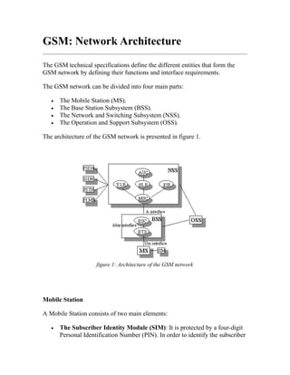
The GSM network can be divided into four main parts:
• The Mobile Station (MS).
• The Base Station Subsystem (BSS).
• The Network and Switching Subsystem (NSS).
• The Operation and Support Subsystem (OSS).
The architecture of the GSM network is presented in figure 1.
figure 1: Architecture of the GSM network
Mobile Station
A Mobile Station consists of two main elements:
• The Subscriber Identity Module (SIM): It is protected by a four-digit
Personal Identification Number (PIN). In order to identify the subscriber
2. to the system, the SIM card contains amongst others a unique
International Mobile Subscriber Identity (IMSI). User mobility is
provided through maping the subscriber to the SIM card rather than the
terminal as we done in past cellular systems.
• Mobile equipment/terminal (ME): There are different types of
terminals (MN) distinguished principally by their power and application:
o `fixed' terminals mainly installed in cars. Their maximum allowed
output power is 20W
o portable terminals can also be installed in vehicles. Their
maximum allowed output power is 8W.
o handheld terminals; their popularity is owed to their weight and
volume, which is continuously decreasing. According to some
specification these terminals may emit up to 0.8W. However, as
technology has evolved their maximum allowed power ouput is
limited to 0.1W.
o
Base Station Subsystem
The BSS provides the interface between the ME and the NSS. It is in charge of
the transmission and reception. It may be divided into two parts:
• Base Station Controller (BSC): It controls a group of BTSs and
manages their radio ressources. A BSC is principally in charge
of handoffs, frequency hopping, exchange functions and power
control over each managed BTSs.
• Base Transceiver Station (BTS) or Base Station: it maps to
transceivers and antennas used in each cell of the network. It is usually
placed in the center of a cell. Its transmitting power defines the size of
a cell. Each BTS has between 1-16 transceivers depending on the density
of users in the cell.
NSS
Its main role is to manage the communications between the mobile users and
other users, such as mobile users, ISDN users, fixed telephony users, etc. It also
includes data bases needed in order to store information about the subscribers
and to manage their mobility. The different components of the NSS are
described below.
3. • MSC: the central component of the NSS. The MSC performs the
switching functions of the network. It also provides connection to other
networks.
• GMSC: A gateway that interconnects two networks: the cellular
network and the PSTN. It is in charge of routing calls from the fixed
network towards a GSM user. The GMSC is often implemented in the
same machines as the MSC.
• HLR: The HLR stores information of the suscribers belonging to the
coverage area of a MSC; it also stores the current location of these
subscribers and the services to which they have access. The location of
the subscriber maps to the SS7 address of the Visitor Location Register
(VLR) associated to the MN.
• VLR: contains information from a subscriber's HLR necessary to
provide the subscribed services to visiting users. When a subscriber
enters the covering area of a new MSC, the VLR associated to this MSC
will request information about the new subscriber to its corresponding
HLR. The VLR will then have enough data to assure the subscribed
services without needing to ask the HLR each time a communication is
established. The VLR is always implemented together with a MSC; thus,
the area under control of the MSC is also the area under control of the
VLR.
• Authentication Center (AuC): It serves security purposes; it provides
the parameters needed for authentication and encryption functions.
These parameters allow verification of the subscriber's identity.
• Equipment Identity Register (EIR): EIR stores security-sensitive
information about the mobile equipments. It maintains a list of all valid
terminals as identified by their International Mobile Equipment Identity
(IMEI). The EIR allows then to forbid calls from stolen or unauthorized
terminals (e.g, a terminal which does not respect the specifications
concerning the output RF power).
• GSM Interworking Unit (GIWU): The GIWU provides an interface to
various networks for data communications. During these
communications, the transmission of speech and data can be alternated.
Operation and Support Subsystem (OSS)
It is connected to components of the NSS and the BSC, in order to control and
monitor the GSM system. It is also in charge of controlling the traffic load of
the BSS. It must be noted that as the number of BS increases with the scaling
of the subscriber population some of the maintenance tasks are transferred to
the BTS, allowing savings in the cost of ownership of the system.
4. Geographical areas
A cell, as identified by its Cell Global Identity (CGI) number, maps to the radio
coverage of a BTS. Similarly an LA as identified by its Location Area
Identity(LAI) number , is a cluster of cells served by a single MSC/VLR.
A group of LA under the control of the same MSC/VLR defines the MSC/VLR
area. A Public Land Mobile Network (PLMN) is the area served
by one network operator.
Network operations
In this paragraph, the description of the GSM network is focused on the
differents functions to fulfil by the network and not on its physical components.
In GSM, five main functions can be defined:
• Transmission: of data and signaling. Not all the components of the
GSM network are strongly related with both types of types of Tx. While
the MSC, BTS and BSC, among others, are involved with data and
signaling, components such as HLR, VLR or EIR registers, are only
concerned with signaling.
• Radio Resources Management (RRM).
• Mobility Management (MM).
• Communication Management (CM).
• Operation, Administration and Maintenance (OAM).
Radio Resources Management (RRM)
The role of the RR function is to establish, maintain and release communication
links between mobile stations and the MSC. The elements that are mainly
concerned with the RR function are the MN and the BTS. However, since the
RR component performs connection management also during cell handoffs, it
also affects the MSC which is the handoff management component.
The RR is also responsible for the management of frequency resources as well
as varying radio interface conditions. Main component operations are:
5. • Channel assignment, change and release.
• Handoff
• Frequency hopping.
• Power-level control.
• Discontinuous transmission and reception.
• Timing advance.
Handoff
The user movements may result a change in the channel/cell, when the quality
of the communication is degrading; this is known as handoff. Handoffs occur
between:
• between channels within a cell
• between cells controlled by the same BSC
• between cells under the same MSC but controlled by different BSCs
• between cells controlled by different MSCs.
Handoffs are mainly controlled by the MSC. However to avoid unnecessary
signalling, the first two types of handoffs are managed by the
respective BSC (thus, the MSC is only notified of the handoff).
To perform the handoff the mobile station controls continuously its own signal
strengh and the signal strengh of the neighboring cells. The list of cells that
must be monitored by the mobile station is given by the base station. Power
measurements allow to decide which is the best cell in order to maintain the
quality of the communication link. Two basic algorithms are used for handoffs:
• The `minimum acceptable performance' algorithm. When the quality of
the transmission degrades, the power level of the mobile
is increased, until the increase of the power level has no effect on the
quality of the signal. Upon this link layer hint, a handoff is initiated.
The `power budget' algorithm. Here the handoff pre-empts the power
increase, to obtain a good SIR.
Mobility Management (MM)
The MM component handles:
6. • Location Management: Location is managed through periodicaly or on-
demand. At power-on time, the MH signals an IMSI attach. On-
demand location updates are signalled when the MN moves to a
different PLMN or new location area (LA). The signal is sent to the new
MSC/VLR, which forwards it to thesubscriber's HLR. Upon
authorization in the new MSC/VLR, the subscriber's HLR removes the
registration entry of the MN at the old MSC/VLR. If after the update
time interval, the MN has not registered, it is then deregistered. On
power-off, the MN performs an IMSI detach.
• security and authentication: Authentication involves the SIM card and
the Authentication Center. A secret key, stored in the SIM card and the
AuC together with a ciphering algorithm called A3, are used to
authenticate the user. The MN and the AuCcompute a SRES through
A3 using the secret key and a nonce generated by the AuC. If the two
computed SRES are the same, the subscriber is authenticated. The
different services to which the subscriber has access are also checked.
Next the a security check is performed in the equipment identity (IMEI).
If the IMEI number of the mobile is authorized in the EIR, the mobile
station is allowed to connect the network. To assure user confidentiality,
the user is registered with a Temporary Mobile Subscriber Identity
(TMSI) after its first location update procedure. Enciphering is another
option to guarantee a very strong security.
Communication Management (CM)
The CM component manages:
• Call control (CC): it controls call setup, management and tear-down in
relation to management of type of service. Call routing is the primary
task for this component. To reach a mobile subscriber, a user dials the
Mobile Subscriber ISDN (MSISDN) number which includes:
o a country code
o a national destination code; this identifies
the subscriber's operator
o a code mapping to the subscriber's HLR.
o The call is then passsed to the GMSC (if the call is originated
from a fixed network) that 'knows' the HLR corresponding to the
particular MSISDN number. The GMSC signals the HLR for call
routing information. The HLR requests this information from the
subscriber's current VLR. This VLRallocates temporarily a
7. Mobile Station Roaming Number (MSRN) for the call. The
MSRN number is the information returned by the HLR to
theGMSC. It is latter that routes the call through the MSRN
number, to the subscriber's current MSC/VLR. In the subscriber's
current LA, the mobile is paged.
• Supplementary Services management: This involves the MN and the
HLR.
SMS management: Here the GSM network contacts the Short Message
Service Center through the two following interfaces:
o SMS-GMSC for Mobile Terminating Short Messages (SMS-MT/
PP). It has the same role as the GMSC.
o SMS-IWMSC for Mobile Originating Short Messages (SMS-MO/
PP).
Operation, Administration and Maintenance (OAM)
The OAM component allows the operator to monitor and control the system as
well as modify the configuration of the elements of the system. Not only the
OSS is part of the OAM, but also the BSS and NSS participate in functions
such as:
• provide the operator with all the information it needs. This information is
forwarded to the OSS to control the network.
• perform self-test tasks in addition to the OAM functions.
• control of multiple BTSs by the BSS.