1. B-Axis Turn/Mills Have Their Place
The additional rotary milling axis on these the distributor of Nakamura-Tome machine tools in the
machines allows them to complete many United States, frequently discusses the fundamentals
types of complex parts in a single setup of a B-axis machine with prospective buyers to be sure
but these machines have gained a reputa- they fully understand its capabilities. Methods provides
tion for being difficult to program. Today’s this standard definition to potential customers: The B-
CAM software, however, eases the pro- axis machine tool combines the turning capabilities of a
gramming challenge significantly. horizontal/vertical turning machine with the milling and
machining capabilities of a five-axis machining center.
Like traditional turn/mill machines, B-axis machine
Many shops today have begun evaluating the purchase
tools provide control over the Z-X (turning) and C (rotary
of multi-function turn/mill machines, weighing factors
milling) axes. The B-axis head is used as a milling
such as cost, capability, and productivity gains. These
spindle or a turning/boring tool holder, thus enabling
shops must consider what type of turn/mill machine
the machine to complete all milling and turning with one
tool best fits their individual needs and the parts they
setup. These machine tools also give users control over
produce. Within the turn/mill machine category is the B-
the Y-axis for off-center milling operations. However, it
axis machine, a turning machine that includes five-axis
is B-axis capability that sets these machines apart. The
milling capabilities. The acquisition of a B-axis machine
B-axis is defined as rotation about the Y axis and this
requires a significant investment, in both money and
fifth axis positioning makes cuts with compound angles
time. B-axis machines are approximately 20 percent
possible. B-axis capability gives a machine full support
higher in price compared to a turn/mill machine of
for five-axis index milling and 3D / 5-axis simultaneous
similar capacity without B-axis features. However, for
freeform milling. The B-axis machine is literally one
shops that produce parts that would benefit from B-axis
machine doing the work of two because it supports the
machining, the productivity gains achieved by B-axis
entire range of milling and turning operations possible,
machines more than justify these expenditures.
with the advantage of doing it in one setup.
Shops evaluating the purchase of a B-axis machine
should ask this key question: What does B-axis ca-
pability add to a turn/mill machine tool and what kind
of CAM system does it take to take advantage of this Whole Part, One Setup
capability successfully? The answer is found by ana- B-axis machines increase part accuracy because they
lyzing the physical characteristics of B-axis machines, hold tighter tolerances between turned and milled
evaluating machine configuration and setup time, and features. For example, when a cutting tool body is
assessing the level of integration of the programming machined on a B-axis machine, it is significantly easier
environment. to maintain geometric tolerances between milling and
turning operations. As with traditional turn/mill ma-
chines, using one workholding eliminates errors that
may be introduced by switching a part from a turning
B-Axis Fundamentals
to a milling machine. For parts that require the turning
Methods Machine Tools Inc. (Sudbury, Massachusetts),
and multi-axis milling operations that only B-axis ma-
a machine tool importer and exclusive distributor who is
chines are equipped to handle, keeping tight tolerances
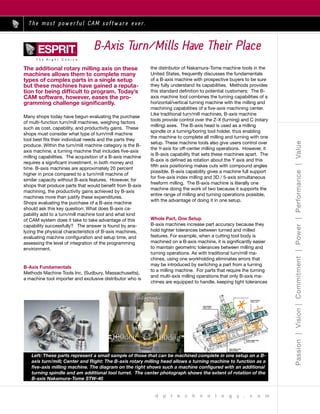
Left: These parts represent a small sample of those that can be machined complete in one setup on a B-
axis turn/mill; Center and Right: The B-axis rotary milling head allows a turning machine to function as a
five-axis milling machine. The diagram on the right shows such a machine configured with an additional
turning spindle and am additional tool turret. The center photograph shows the extent of rotation of the
B-axis Nakamura-Tome STW-40
2. across multiple datums is especially important for main- 20-inch diameter metal casting can benefit from B-axis
taining geometric tolerances between features. machining.
When outfitted with dual spindles, the extended ma- To accommodate the different machining needs of its
chining range of a B-axis machine enables it to perform customers, Methods Machine Tools offers two models
both milling and turning operations, on both the front of Nakamura Tome machine tools equipped with a B
and back of the workpiece. Each spindle (main and axis. The STW-40 model (standard 40 Tool ATC) is
sub) acts as a workpiece holder, allowing simultaneous designed to handle large, heavy parts such as cast-
five-axis cutting on either the front or back of the part, ings and forgings and can accommodate work pieces
thereby completing the entire part in one setup. A job up to 17 inches in diameter. However, in response to
that previously required four setups (front-turn, back- customer demand, Methods now offers a smaller model
turn, front-mill, back-mill) can be reduced to one setup B-axis machine, the NTJ (B-axis turret). This model is
on a machine with B-axis capability. roughly half the weight and size of the STW-40, has the
advantage of taking up less floor space, and is easier to
A multi-spindle B-axis machine outfitted with a lower maintain and run than its larger counterpart. The NTJ
turret further increases capacity for producing parts in a is best used for the machining of smaller B-axis parts,
single setup. See Figure 1. In this configuration, the B- such as arthroscopic tools, that don’t exceed 8-inch
axis head operates at the same time other turret-based diameters. See box on page XXX.
cutting tools are being used on the opposite spindle,
enabling synchronized simultaneous machining. In Both models are equipped with barfeed capability,
other words, cutting occurs on both the front and back enabling shops to feed stock into the machine tool in a
of the part at the same time. continuous stream and then perform B-axis cutting, if
needed, on part features with compound angles. For
example, a shop producing large volumes of watch
What B-Axis Parts Look Like bodies could utilize this type of machine for uninter-
Cylindrical parts with milled features at compound rupted machining. When evaluating parts and barfeed
angles or on multiple faces are surprisingly common. options, shops should consider the size of the stock.
Shops serving the heavy equipment and oil service in- While a larger B-axis machine equipped with barfeed
dustries, producing parts that demand precise five-axis can handle larger bar stock, it is not always practical
contouring and finishing often use B-axis machines to to feed stock of this magnitude into a machine tool.
manufacture shafts with slots, grooves, and cutouts at Because bar stock tends to be long (a length of 12 feet
compound angles. Shops also use B-axis machines for is not uncommon), it may prove to be too heavy for a
intricate, multi-faced parts, such as cutting tool bodies person or robot to lift. Large stock is also difficult to cut
and holders. See Figure 2. when it comes time to part off the slug.
The size of B-axis parts can vary greatly. Parts as small In addition, shops should also consider the “unexpect-
as a 0.04-inch diameter watch gear or as large as a ed” parts that don’t necessarily have B-axis features
This cutter body is representative of the multi-faced parts that are ideally suited for B-axis machining.
The screen capture on the left shows how the B-axis allows machining of features at a compound angle.
3. (features at compound angles and or on multiple faces) would not have to do the turning portion of the part
but that still require both milling and turning work. For in one software application and the milling portion of
example, a company may machine a subset of hydrau- the part in another software application and then try to
lic components that requires B-axis machining, but find coordinate the two effectively.
a majority of its jobs require both traditional milling and
turning operations. For this type of shop, purchasing a For this reason, the company developed the Esprit
B-axis machine will enable the shop to meet the entire SolidMillTurn product line. Released in March 2003,
range of its turn/mill machining needs. this software offers a suite of machining cycles for two-
to five-axis milling, including three-axis and simultane-
ous five-axis 3D multi-surface/solid machining, as well
Easier Programming as support for turning cycles such as facing, boring,
Once a shop has decided that a B-axis machine fits its grooving, and threading. The software gives program-
needs and the parts it produces, primary concern shifts mers the flexibility to use milling and turning cycles in
to ensuring that CNC programmers have the CAM tools any combination in one session on a single workpiece:
capable of programming these machines. Effective On the front or back of the part, with the primary or
CAM software enables shops to take full advantage of secondary spindle, with the upper B-axis head or lower
the capabilities of B-axis machines by providing tools turret.
that create, optimize, and verify CNC programs ef-
ficiently. Watching a B-axis machine in action (particu- As part of this software, one programming tool that is
larly for the first time) can be quite intimidating because especially important for programming B-axis machines
of its complex configuration, simultaneous machining, is Work Planes. Each part feature is automatically
and non-perpendicular multi-axis tool movements. assigned to the most appropriate Work Plane, thus
Therefore, it is essential that a CAM system give simplifying the programming of parts for B-axis machin-
programmers full control over all machine movements. ing. Work Planes define the orientation of the "C" and
This control eases the challenge of programming these "B" axes, making it easy to drill and mill features that
complex machines, and the availability of such software are at compound angles (B-axis features). See Figure 3.
should encourage more shops to consider the produc- For example, instead of programming a simultaneous
tivity advantages of such equipment. X and Z-axis move to drill a hole at an angle, program-
mers can use Work Planes to define the angles of the
When CAM software developer DP Technology (Ca- "C" and "B" axes, thus automatically rotating the ZX
marillo, California) began to study the programming coordinate system and requiring the programmers
considerations for workpieces produced on B-axis to only specify a single Z-axis move; in actuality, the
machines, it recognized that a system using one, fully machine will move both the X and Z axes to produce
integrated mill/turn programming environment would the hole. Work Planes enable users to establish "local
simplify the programming of these machines and coordinate systems" which simplify the actual G-Code
provide shops with the flexibility they need to program used to produce a given feature and make it easier for
B-axis parts efficiently and accurately. Essentially, an in- the operator to understand. Software tools that syn-
tegrated programming environment means that a shop chronize and optimize machining operations through a
Left: To program machining operations on workpeice surfaces that are tilted at more than one angle
from the main machine axes, work planes treat the orientation of the surface as if it corresponds with
the X and Z axes of the machine tool; Center: Simulation allows the programmer to visually check a
program for axis moves that may present a collision hazard. Simulation is especially valuable when both
spindles are moving at once; Right: The Nakamura-Tome NTJ is a B-axis turn/mill at the smaller end of
the size range for this type of machine tool. It can machine workpieces as large as 8 inches in diameter.
4. single interface are helpful for organizing the turn/mill Productivity Partners
program. DP Technology believes that an effective In recent years machine tool manufacturers and CAM
synchronization tool fully integrates all machining, not software developers have begun forging relationships
only offering a combined display listing both milling to meet the needs of shops using B-axis machines.
and turning operations and their associated cycle The goal is to win wider acceptance of these ma-
times, but also adapting its view to meet the number of chines for the appropriate applications by overcoming
turrets, heads, or spindles supported by the machine. the user’s resistance based on the perception that
Logistically this simplifies programming by only requir- these machines are difficult to program. For example,
ing users to go to one location to find out how the part Methods Machine Tools has successfully worked with
is being machined. The ability to move, copy, edit, and the Esprit CAM system and its application team in a
synchronize operations through a single interface also partnership that has produced an effective program-
helps make optimizing the part program easier. ming solution for its B-axis customers.
This cooperation between machine tool dealer and
Time studies that automatically calculate cycles time CAM software developer offers significant benefits
used in combination with a comprehensive simulation for shops purchasing B-axis machines because the
and verification tool are extremely valuable in B-axis solution offered saves a significant amount of software
machining where tool crashes are a constant concern setup time, enabling them to immediately take ad-
for shops. Shops using B-axis machines will find it vantage of the productivity these machines offer. For
very useful to be able to program a series of mill and example, customers are assured of having a working
turn operations, optimize the cycle times, and then postprocessor because the two suppliers have devel-
simulate these operations at any point in the program- oped the postprocessors together and have tested
ming process to verify there are no tool collisions. them on sample B-axis parts. Further, the configura-
tion of particular machines has already been defined in
To verify CNC programs effectively, it is helpful if simu- the CAM system’s Machine Setup and is available right
lation truly mimics machine operation. For example, away.
Esprit’s Machine Setup provides an interface for shops
to define the configuration and number of turrets and
spindles of the shop’s specific machines to ensure Compelling
accurate simulation. Further, to provide effective The B-axis machine’s potential for increasing produc-
programming for B-axis machining, this CAM system tivity and producing multi-faceted parts in a single
shows the entire part on screen along with the key setup are compelling reasons for shops to invest the
moving elements of the machine tool (spindles, turrets, time and money in this type of turn/mill machine tools.
B-axis heads, tooling), not just sections of it, in order Shops that hesitate over concern about the program-
to protect against potential crashes, especially during ming challenge have no reason to do so. Partnerships
synchronized simultaneous machining or transferring between knowledgeable machine tool dealers and
of the part from the main to sub spindle. See Figure 4. experienced CAM providers assure that a new B-axis
Once the tool path is generated and verified, the post- machine will reach its potential because it has the
processor produces the G-code program for all milling necessary programming capability in place to maximize
and turning operations. This is an advantage over productivity.
software requiring the user to postprocess turning and
milling tool paths separately and then combine them
into one program to download to the shop floor.
DP Technology Corp., 1150 Avenida Acaso, Ca-
marillo, CA 93012. Tel.: 805-388-6000 Fax: 805-
388-3085. Website: www.dptechnology.com. E-mail:
esprit@dptechnology.com.